
Related Manuals for THORLABS LFEPL


Summary of Contents for THORLABS LFEPL
- Page 1 LFEPL and LFEPS Acrylic Panel Kits LFEPL and LFEPS Acrylic Panel Kits Installation Manual Enclosure Frame not Included Original Instructions...
- Page 2 LFEPL and LFEPS Acrylic Panel Kits Table of Contents Introduction ........................1 Chapter 1 Safety..........................2 Chapter 2 2.1. General Warnings and Cautions ................2 Installation ........................3 Chapter 3 3.1. Environmental Conditions ..................3 3.2. Parts List ........................4 3.3.
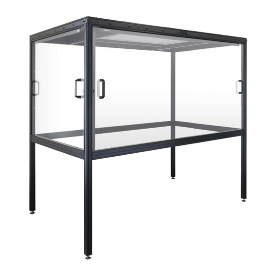
- Page 3 The LFEPL and LFEPS Acrylic Panel kits have been designed to allow a solid-walled enclosure to be fitted to the LFE1220 Optical Table Frames. The LFEPS panel fits to the shorter side of the enclosure and the LFEPL panel fits to the longer side.
- Page 4 LFEPL and LFEPS Acrylic Panel Kits Chapter 2: Safety Chapter 2 For the continuing safety of the operators of this equipment, and the protection of the equipment itself, the operator should take note of the Warnings, Cautions and Notes throughout this handbook and, where visible, on the product itself.
- Page 5 LFEPL and LFEPS Acrylic Panel Kits Chapter 3: Installation Chapter 3 3.1. Environmental Conditions Warning Operation outside the following environmental limits may adversely affect operator safety. Location Indoor use only Maximum Altitude 2000 m Temperature Range 5°C to 40°C Maximum Humidity Less than 80% RH (non-condensing) at 31°C...
- Page 6 LFEPL and LFEPS Acrylic Panel Kits Chapter 3: Installation 3.2. Parts List Description Qty LFEPL Qty LFEPS Image Long Acrylic Panel Short Acrylic Panel Long Attachment Bracket with Logo Short Attachment Bracket with Logo Short Attchment Bracket Lifting Handle XE Slot Cover Profile...
- Page 7 LFEPL and LFEPS Acrylic Panel Kits Chapter 3: Installation 3.3. Fitting the Acrylic Panel Peel off the protective film. Using the M6 x 20 Socket Cap Screws, M6 Plain Washers, and M6 Nuts supplied, fit the Lifting Handles to the Acrylic Panels as shown below.
- Page 8 LFEPL and LFEPS Acrylic Panel Kits Chapter 3: Installation Using qty two M6 Nuts, fit two of the Hammerhead Screws to one of the short attachment brackets as shown below. Tighten the nut two rotations such that the Hammerhead Screw is loose in the bracket.
- Page 9 Repeat steps 4 to 6 for the remaining Short Attachment Bracket. For the LFEPL panel, repeat steps 4 and 5 for the Long Attachment Bracket, fitting qty four Hammerhead Screws and M6 Nuts. For the LFEPS panel, repeat steps 4 and 5 for the Short Attachment Bracket with Logo, fitting qty 2 Hammerhead Screws and M6 Nuts.
- Page 10 LFEPL and LFEPS Acrylic Panel Kits Chapter 3: Installation Turn the heads of all the Hammerhead Screws in the Attachment Bracket such that they are parallel with the horizontal slots in the frame extrusion, then align the bracket with the frame as shown below. Fit the heads of the Hammerhead Screws into the rearmost slot in the extrusion, then turn each screw through 90°...
- Page 11 LFEPL and LFEPS Acrylic Panel Kits Chapter 3: Installation 10. Slide the Attachment Bracket such that it is centered along the extrusion length as shown below. Figure 5 Locating the Attachment Brackets Rev A May 2022 Page 9...
- Page 12 LFEPL and LFEPS Acrylic Panel Kits Chapter 3: Installation 11. Tighten the nuts and fit the M6 Nut Covers. 12. Fit the Slot Cover Profile into the front extrusion slot of the lower cross member as shown below. Figure 6 Fitting the Slot Cover Profile...
- Page 13 LFEPL and LFEPS Acrylic Panel Kits Chapter 3: Installation 13. Align the Acrylic Panel with the lower extrusion cross member and lower the bottom edge into the recess in the slot cover profile as shown below. Figure 7 Lowering the Panel into the Slot Cover Profile...
- Page 14 LFEPL and LFEPS Acrylic Panel Kits Chapter 3: Installation 14. Tilt the panel upwards until it rests against the attachment brackets previously fitted, then using the M4 x 10 mm Thumbscrews and M4 Flat Washers provided, attach the Acrylic Panel to the brackets as shown below.
- Page 15 LFEPL and LFEPS Acrylic Panel Kits Chapter 4: Specifications Chapter 4 General Specifications LFEPS LFEPL Panel Material Acrylic Plastic (PPMA) Panel Dimensions (W x L) 1220.0 mm x 1067.0 mm 2090.0 mm x 1067.0 mm (48.03 2.01 (82.28 2.01 Weight 5.0 kg (11.0 lb)
- Page 16 Contact Thorlabs for more information. Waste treatment is your own responsibility. End of life units must be returned to Thorlabs or handed to a company specializing in waste recovery. Do not dispose of the unit in a litter bin or at a public waste disposal site.
- Page 17 www.thorlabs.com...
Need help?
Do you have a question about the LFEPL and is the answer not in the manual?
Questions and answers