Advertisement
For questions or help with this product contact Tech Support at (570) 546-9663 or techsupport@grizzly.com
Introduction
This taper attachment provides precision outside
and inside tapers up to 12" without having to off-
set the tailstock.
Another feature is the ability to use the attach-
ment without disengaging the cross slide. This
allows the taper attachment to be functional at any
time by simply tightening the bed clamp bracket.
However, the taper attachment does not interfere
with other turning operations.
This taper attachment features scales at both
ends, reading inches-of-taper per foot and angle
of taper. An adjustment knob with fine threads
achieves precise control when setting tapers.
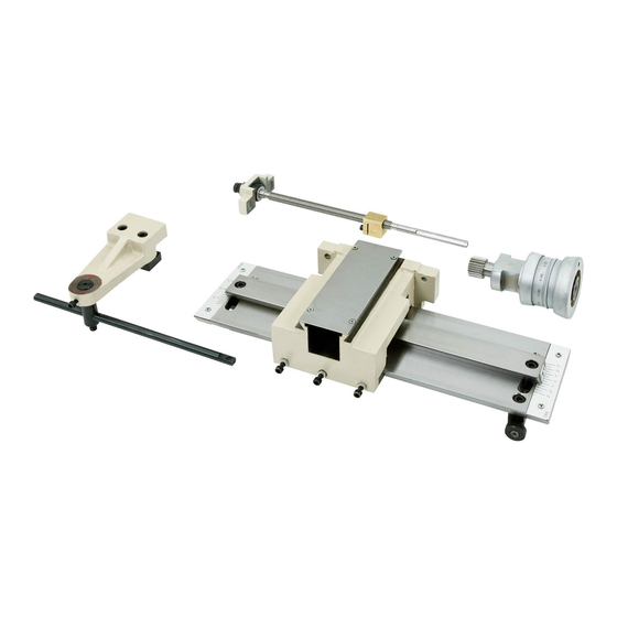
Identification
A
B
C
Figure 1. Taper attachment identification.
A. Bed Clamp: Secures the taper attachment
to a specific position on the bedway and
enables the use of the taper attachment.
OR FORM WITHOUT THE WRITTEN APPROVAL OF GRIZZLY INDUSTRIAL, INC.
FOR MODELS MANUFACTURED SINCE 3/13 #TS15756 PRINTED IN CHINA
D
COPYRIGHT © JULY, 2013 BY GRIZZLY INDUSTRIAL, INC.
NO PORTION OF THIS MANUAL MAY BE REPRODUCED IN ANY SHAPE
MODELS T10502, T10556,
TAPER ATTACHMENT
B. Slide Table: Connects to the bed clamp and
provides a stable platform for the pivot bar.
C. Body: Houses the pivot and slide blocks that
connect to the cross slide.
D. Taper Adjustment Knob: Adjusts the angle
of the pivot bar for the desired taper.
E. Pivot Bar: Provides an angled dovetail path
to guide the tooling for the desired taper.
Specifications
Model T10556 ...... for G4002, G4003, & G4003G
Model T10502 .......................................for G0709
Model T26300 ................................... for G0750G
Maximum Taper Length .................................... 9"
Taper Per Inch Range .............................. 0"– ±3"
Inch Scale Divisions ........................................
Taper Angle Range ..................................0°– ±5°
Angle Scale Divisions ....................................... 1°
Construction ................................Cast Iron, Steel
Shipping Weight ........................................ 60 lbs.
E
This taper attachment is heavy! Get
assistance when installing it on the lathe.
To reduce the risk of crushing injuries, wear
boots with toe protection and keep hands
and fingers away from all pinch points.
& T26300
INSTRUCTIONS
⁄
"
1
2
Advertisement
Table of Contents

Related Manuals for Grizzly T10502


Summary of Contents for Grizzly T10502
- Page 1 MODELS T10502, T10556, & T26300 TAPER ATTACHMENT INSTRUCTIONS For questions or help with this product contact Tech Support at (570) 546-9663 or techsupport@grizzly.com Introduction B. Slide Table: Connects to the bed clamp and provides a stable platform for the pivot bar.
-
Page 2: Required For Setup
— Cap Screw M6-1 x 14......1 Remove the compound rest from the cross slide by removing the (2) hex nuts shown in Figure 3. Hex Nuts Figure 2. Shipping inventory. Figure 3. Hex nuts that secure the compound rest. T10502, T10556, T26300 (Mfg. Since 3/13) - Page 3 This cap screw secures the cross slide to the leadscrew nut. Handwheel Retainer Cap Screw Screw Installation Hole Figure 7. Handwheel retainer set screw location. Figure 5. Cap screw removed that secures cross slide to leadscrew nut. T10502, T10556, T26300 (Mfg. Since 3/13)
- Page 4 13. Slide the taper attachment body off the pivot for now. It is not necessary to disconnect the bar. wires at this time. Note: For the Model G0709, the bracket assembly also includes the coolant nozzle. T10502, T10556, T26300 (Mfg. Since 3/13)
- Page 5 17. Mount the attachment body to the saddle, as shown in Figure 12. Taper Attachment Leadscrew 18. Remove the top cover from the taper attach- ment. Alternate Leadscrew Rear Bracket Figure 14. Alternate leadscrew rear bracket on taper attachment leadscrew. T10502, T10556, T26300 (Mfg. Since 3/13)
- Page 6 (see to Step 31 and Figure 20 on Page 7 for orientation reference). Taper Attachment Handwheel Figure 17. Handwheel comparison. T10502, T10556, T26300 (Mfg. Since 3/13)
- Page 7 (see Figure 19). Alignment Block Pivot Block M6-1 x 35 Cap Screws Cap Screws Figure 21. Bed clamp bracket and block Figure 19. Pivot and alignment blocks attached to bedway (bottom view). re-installed. T10502, T10556, T26300 (Mfg. Since 3/13)
- Page 8 39. Move the carriage toward the spindle as far as possible. Note: Adjust components as necessary to expose as much of the pivot bar as possible on the tailstock side of the taper attachment body. T10502, T10556, T26300 (Mfg. Since 3/13)
- Page 9 (see Figure 26). Strain Relief Original Hole Extension Shaft Threaded into Second Hole Figure 26. Extension shaft threaded into second hole of lamp bracket. T10502, T10556, T26300 (Mfg. Since 3/13)
-
Page 10: Operation
Figure 29. Taper determined by angular measurement. In this case, the angular scale on the tailstock end of the slide table would be set at the desired angle of the taper. Figure 31. Location of bracket cap screws. -10- T10502, T10556, T26300 (Mfg. Since 3/13) - Page 11 Move the carriage by hand to make sure there is the proper amount of travel to turn the taper. Make adjustments to the taper attachment as necessary. -11- T10502, T10556, T26300 (Mfg. Since 3/13)
-
Page 12: Maintenance
(see Figure 35), apply a thin coat of a quality way oil to these surfaces (see Page 16 To reduce risk of shock or for an offering from Grizzly). Slide the attachment accidental startup, always body back and forth along the slide table to dis-... -
Page 13: Gib Adjustment
When satisfied with the movement, retighten the hex nuts to secure the setting. To recheck the settings, repeat Step 2. -13- T10502, T10556, T26300 (Mfg. Since 3/13) -
Page 14: Parts Diagram
Parts Diagram 10 11 -14- T10502, T10556, T26300 (Mfg. Since 3/13) -
Page 15: Parts List
PHLP HD SCR M3-.5 X 8 PT10556103 BED CLAMP BRACKET (T10556 & T26300) PT10556137 REAR COVER PT10502103 BED CLAMP BRACKET (T10502) PCAP03M CAP SCREW M5-.8 X 8 PT10556104 ALTERNATE LEADSCREW REAR BRACKET PT10556139 ANGLE SCALE PLATE -15- T10502, T10556, T26300 (Mfg. Since 3/13) - Page 16 Figure 40. T23964 Armor Plate with Moly-D Multi-Purpose Grease Figure 42. Model G9766 Drill & Tap Set. www.grizzly.com 1-800-523-4777 order online at or call -16- T10502, T10556, T26300 (Mfg. Since 3/13)
Need help?
Do you have a question about the T10502 and is the answer not in the manual?
Questions and answers