Table of Contents
Advertisement
Quick Links
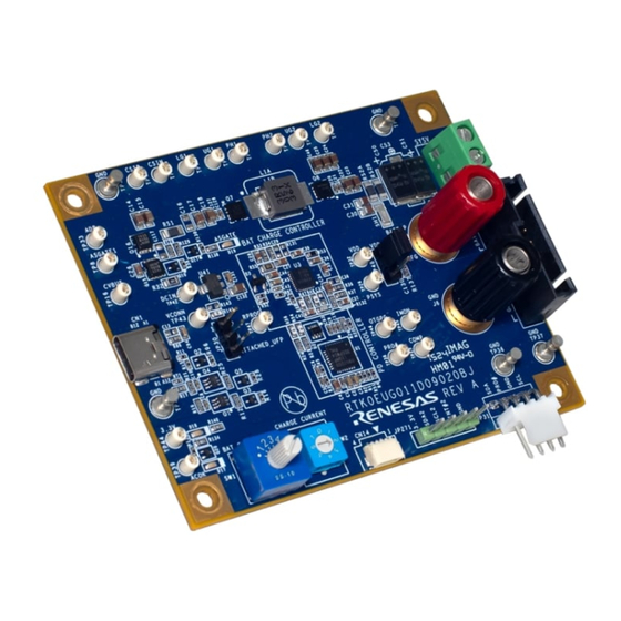
RTK0EUG011D09020BJ
100W USB Type-C Battery System Reference Design for 2 to 7S Li-Ion
Description
The RTK0EUG011D09020BJ (RTK-251-SinkCharger-RAA489118) is an evaluation board for Universal Serial Bus
Power Delivery (USB PD). The RTK-251-SinkCharger-RAA489118 is designed with USB PD controller
R9A02G011 and On-Board Charger RAA489118 to support 2 to 7 battery cells in series configuration. This
document is the instruction manual for the RTK-251-SinkCharger-RAA489118.
The RTK-251-SinkCharger-RAA489118 supports USB PD 2.0, USB PD 3.1, and USB Type-C
RTK-251-SinkCharger-RAA489118 works as a USB Type-C power sink charger or a power bank. The board does
not have a battery protection circuit on it, so Renesas strongly recommends using a battery module with Renesas'
Battery Management System to avoid over-discharging under the power bank mode. The RTK-251-SinkCharger-
RAA489118 can be combined with an Evaluation Module of the Battery Fuel Gauging IC (FGIC) RAJ2400100 with
Filefish to realize a complete Battery Management System (BMS).
The configuration switches enable the selection of the number of battery cells, the maximum charge current and
the operating mode.
VIDWriter 1.1.0.0 applies to the RTK-251-SinkCharger-RAA489118.
Target Devices
▪ 100W USB Type-C Charger or MAX 60W Power Bank: RTK-251-SinkCharger-RAA489118
• USB Power Delivery Controller: R9A02G011
• On-Board Charger: RAA489118
▪ Evaluation Module of Battery Fuel Gauging IC (FGIC) with Filefish: RAJ240100 Filefish EVM
• Battery Fuel Gauging IC: RAJ240100
Target VIDWriter
▪ VIDWriter 1.1.0.0 (Version 1.1.0.0)
Related Document
Use this document in combination with the following documents.
The related documents mentioned in this publication may include preliminary versions. However, preliminary
versions are not marked as such.
▪ R9A02G011 Datasheet: R19DS0088EJ
▪ R9A02G011 User's Manual: R19UH0102EJ
▪ E1 Emulator E20 Emulator User's Manual: R20UT0398EJ
▪ E2 Emulator Lite User's Manual: R20UT3240EJ
▪ E1/E20 Emulator, E2 Emulator Lite Additional Document for User's Manual (Notes on Connection of RL78):
R20UT1994EJ
▪ Renesas Flash Programmer V3.13 Flash memory programming software User's Manual: R20UT5312EJ
▪ USB Power Delivery Controller VIDWriter 1.1.0.0 Instruction Manual: R19AN0272EJ
▪ RAA489118 Short-Form Datasheet: R16DO0024EU
▪ RAJ240100 Datasheet: R01DS0301EJ
▪ RAJ240100 Filefish User's Manual: R01AN6763EJ
R16UZ0114EU0100 Rev.1.00
Nov 13, 2024
Manual
®
Specification. The
Page 1
© 2024 Renesas Electronics
Advertisement
Table of Contents

Related Manuals for Renesas RTK0EUG011D09020BJ


Summary of Contents for Renesas RTK0EUG011D09020BJ
- Page 1 RTK-251-SinkCharger-RAA489118 works as a USB Type-C power sink charger or a power bank. The board does not have a battery protection circuit on it, so Renesas strongly recommends using a battery module with Renesas’ Battery Management System to avoid over-discharging under the power bank mode. The RTK-251-SinkCharger- RAA489118 can be combined with an Evaluation Module of the Battery Fuel Gauging IC (FGIC) RAJ2400100 with Filefish to realize a complete Battery Management System (BMS).
-
Page 2: Table Of Contents
Renesas BMS Interface ........... 13 3.2.3 Charging Battery Module with Renesas BMS Interface ......13 3.2.4 Power Bank Mode Setting . -
Page 3: Features
◦ Charging Current limits control for R9A02G011 • On-chip debugging emulator interface ◦ Renesas on-chip debugging emulator interface to write and debug firmware for R9A02G011. • Battery Management System interface ◦ Renesas BMS evaluation board interface to communicate with Battery module including FGIC. -
Page 4: Component
RTK0EUG011D09020BJ Manual Component 1.2.1 Component Layout J5&J6/J17 JP271 CN14 JP31 Top Side Bottom Side Figure 2. Highlighted Main Parts on the Board R16UZ0114EU0100 Rev.1.00 Page 4 Nov 13, 2024... -
Page 5: Component Information
Remark R9A02G011 (USB Power Delivery Controller) RAA489118 (On-Board Charger) Table 2. Connectors Description Remark USB Type-C receptacle CN14 Renesas on-chip debugging emulator interface JP30 USB2.0 Data interface Connector for VSYS J5&J6 Connector for Battery interface /J17 JP271 SMBus Target SCL, SDA, alert on R9A02G011... -
Page 6: Function Assignment For R9A02G011
RTK0EUG011D09020BJ Manual Function Assignment for R9A02G011 Figure 6 shows the functions assigned to R9A02G011 on RTK-251-SinkCharger-RAA489118. Table 6. Functions Assigned to R9A02G011 Pins on RTK-251-SinkCharger-RAA489118 Pin Name Function Description Open Reserved VBUSM voltage monitor input Input for Over Temperature Protection... -
Page 7: Function Assignment For Raa489118
RTK0EUG011D09020BJ Manual Function Assignment for RAA489118 Table 7 shows the functions assigned to RAA489118 on RTK-251-SinkCharger-RAA489118. Table 7. Functions Assigned to RAA489118 Pins on RTK-251-SinkCharger-RAA489118 Pin Name Function Description CSON CSON Battery current sense -input CSOP CSOP Battery current sense +input... -
Page 8: Function
Function Battery Configuration Battery Configuration is set by SW1. Table 8. Rotary Switch Setting Value for Battery Configuration SW Position RTK0EUG011D09020BJ: 2-7 Cells Version 2 Cells in series 3 Cells in series 4 Cells in series 5 Cells in series... -
Page 9: Charging Current Limits
RTK0EUG011D09020BJ Manual MaxSysVol represents the maximum battery charging voltage. It is defined as Full in this document. If VBAT reaches the Full value, the charger operates in Constant Voltage mode. MinSysVol represents the minimum allowed voltage during discharging mode. It is defined as Empty in this document. In charging mode, when VBAT is less than the Empty value, the Charger trickle charges the battery at a low current level. -
Page 10: Operating Mode Selection
RTK0EUG011D09020BJ Manual If SW2 does not have a suitable charging current value and/or setting MaxSysVol and MinSysVol as standard values is not required, set SW2 to SW position 0 and set the expected charging current value, MaxSysVol and MinSysVol. Install them on FW that is generated by using the VIDWriter 1.1.0.0 as described in... -
Page 11: Sourcing Mode
IMPORTANT: The RTK-251-SinkCharger-RAA489118 does not have a battery protection circuit on the board, so, Renesas strongly recommends using a battery module with Renesas’ Battery Management System to avoid over discharging under the power bank mode. RTK-251-SinkCharger-RAA489118 can support power bank mode as long as the battery module uses a protection circuit to avoid over-discharge and over-temperature. -
Page 12: Board Setup And Usage
EPR cable is required.) Note: This board does not require an external power supply except for the batteries. IMPORTANT: USE THIS BOARD WHEN YOU UNDERSTAND AND AGREE THAT RENESAS DOES NOT HAVE ANY RESPONSIBILITY, INDEMNIFICATION, OR LIABILITY FOR USE OF THIS BOARD. -
Page 13: Charging Battery Module With The Custom Charger Parameters (Manual Mode) Without Renesas Bms Interface
6. The board supplies power to battery module. 7. FW of RTK-251-SinkCharger-RAA489118 frequently retrieves the maximum charging voltage and current limits using the Renesas BMS interface and updates the battery charger setting value on RTK-251- SinkCharger-RAA489118. Note: Never change SW1/SW2 when the Board power is ON. -
Page 14: Battery Module With Renesas Bms Interface
Function. Battery Module with Renesas BMS Interface Battery module with Renesas BMS interface is described in this section. Renesas release Filefish that is a fixed firmware solution for Renesas Battery Fuel Gauging IC (FGIC), which requires no additional firmware development. Using this solution, the battery management system (BMS) can be easily and quickly designed, and the time to market can be significantly reduced. -
Page 15: Raj240100 Filefish Evm
Refer to RAJ240100 Filefish User’s Manual (R01AN6763EJ) for more details. Figure 8. RAJ240100 Filefish EVM Note: Minimum number of cells for Filefish (RAJ240100) is 3 cells in series. For more information about Filefish, contact your Renesas representative. Firmware Writing to the R9A02G011 on RTK-251-SinkCharger- RAA489118 This section describes how to generate and write the firmware (such as Intel HEX file) to the R9A02G011 in an appropriate method. - Page 16 VID/PID(0xFFFF/0x0000) numbers set in this field, overwrite the numbers to this field. Otherwise, leave VID: FFFF and PID: 0000. 4. Window for the Renesas recommended turnkey solution ‒ RTK-251-SinkCharger-RAA489118 is displayed as the Renesas recommended turnkey solution in Field D.
- Page 17 Figure 10. Main Window for VIDWriter 1.1.0.0 after Product Configuration 5. Field E configures the turnkey solution recommended by Renesas. ‒ Field E sets the Full, Empty, Max Charging Current, and Max sourcing PDP (DRP mode). There are three operating modes; Board, BMS, and Manual.
- Page 18 RTK0EUG011D09020BJ Manual Figure 11. Field E and the EVB Setting vs Board Configuration Full indicates the maximum battery charging voltage. Empty indicates the voltage at which the charger trickle charges the battery at a low current level if VBAT is below that value.
- Page 19 RTK0EUG011D09020BJ Manual Figure 13. Field E and the EVB setting vs Manual Configuration If there is no suitable charging current value on SW2 and/or setting Full and Empty as standard values is not required, set SW2 to SW position 0 and set the expected charging current value, Full and Empty. Full indicates the maximum battery charging voltage.
-
Page 20: Outline Of Flash Memory Writing
7. Finally, after selecting the Create FW Data button, a file save dialog is displayed. The default storage location is the My Documents folder. The save location and file name of the ROM image can be changed if required. If rewriting this ROM image to R9A02G011 on the evaluation board, use the Renesas Flash Programmer V3 programming software. - Page 21 RTK0EUG011D09020BJ Manual Table 19. Wiring between R9A02G011GNP and Dedicated Flash Memory Programmer Pin No. Pin Configuration of Dedicated Flash Memory Programmer R9A02G011GNP 32pin Pin name Signal Name E1, E2, E2 Lite, E20 Pin Function HVQFN PG-FP6 on-chip debugging emulator Transmit/receive...
-
Page 22: Fw Writing With Renesas On-Chip Debugging Emulator
RAA489118 does not have a full 14-pin connector for the emulator, connecting using a converter is required. The converter is made with a bundled cable when using Renesas on-chip debugging emulator. 1. Connect the conversion connector to CN14 on the board. - Page 23 RTK0EUG011D09020BJ Manual 8. Click the Tool Details and select the 3.3V in the Power Supply area, then click Connect. Figure 17. Tool Details Window 9. The following window appears if the new project is created correctly. Figure 18. Project Information Window Note: Confirm that the Microcontroller can detect D720251.
- Page 24 RTK0EUG011D09020BJ Manual 10. Select the Erase, Program, and Verify in the Operation Settings tab. Figure 19. Operation Settings Tab 11. Click Start to start programming the flash memory data Figure 20. Operation Tab - Start Programming R16UZ0114EU0100 Rev.1.00 Page 24...
-
Page 25: Optional Features
Figure 23. Connector for SMBus Target Interface To control the RTK-251-SinkCharger-RAA489118 board using an external controller through the SMBus Target Interface, connect the SMBus Controller signaling of the system to JP271. When the system wants to control RTK-251-SinkCharger-RAA489118, contact Renesas for support. R16UZ0114EU0100 Rev.1.00 Page 25... -
Page 26: Ordering Information
RTK0EUG011D09020BJ Manual Ordering Information Part Number Description RTK0EUG011D09020BJ RTK-251-SinkCharger-RAA489118 (2-7 Cells) Revision History Revision Date Description 1.00 Nov 13, 2024 Initial release. R16UZ0114EU0100 Rev.1.00 Page 26 Nov 13, 2024... - Page 27 Unit Products The following usage notes are applicable to all Microprocessing unit and Microcontroller unit products from Renesas. For detailed usage notes on the products covered by this document, refer to the relevant sections of the document as well as any technical updates that have been issued for the products.
-
Page 28: Corporate Headquarters
Renesas Electronics disclaims any and all liability for any damages or losses incurred by you or any third parties arising from the use of any Renesas Electronics product that is inconsistent with any Renesas Electronics data sheet, user’s manual or other Renesas Electronics document.
Need help?
Do you have a question about the RTK0EUG011D09020BJ and is the answer not in the manual?
Questions and answers