Advertisement
Specifications
| Range / Capacity | Level 1 | Level 3 | Level 4 |
| Pressure Range: | 30 – 100 psi (210 – 690 kPa) | ||
| Temperature Range: | 40 –100°F (4.4 – 38°C) | ||
| Rated Service Flow: | 0.5 gpm (1.9 Lpm) | ||
| Filter Capacity: | 3000 gallons (11,356 L) | 500 gallons (1893 L) | |
| Turbidity: | 5 NTU max | ||
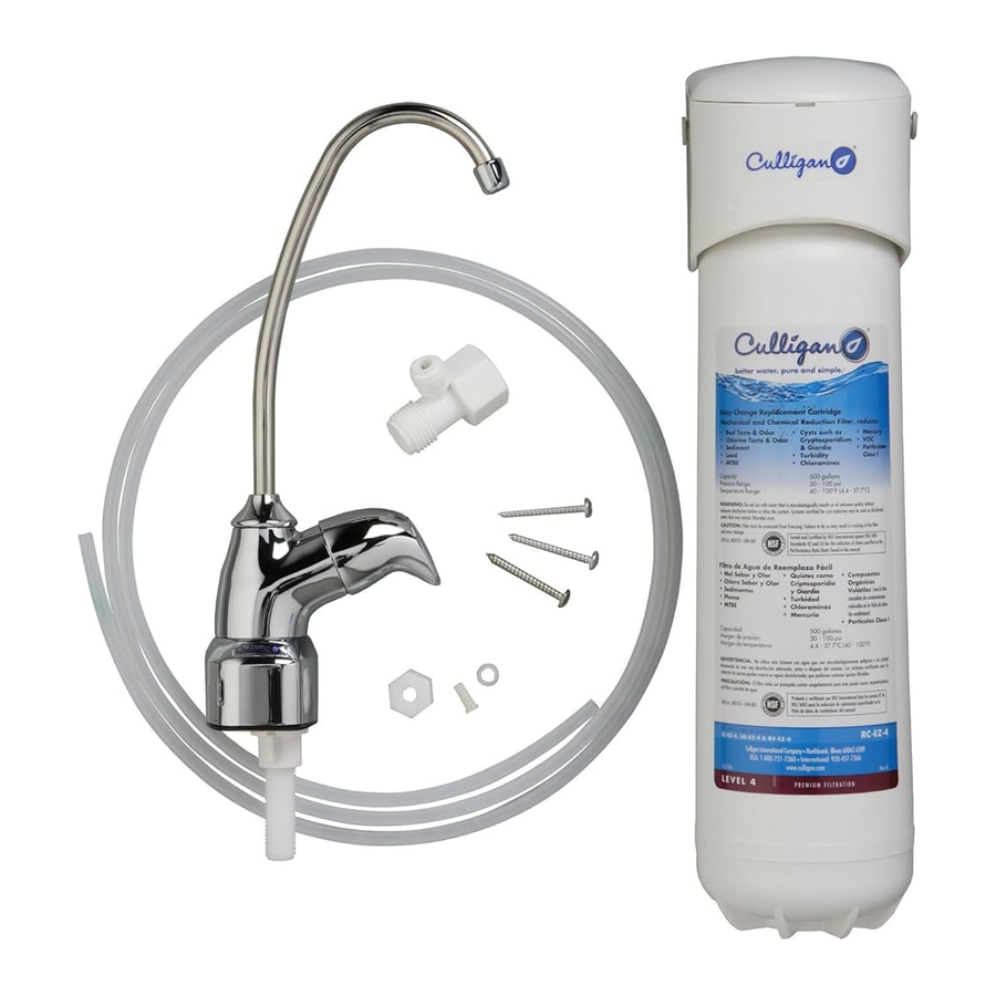
Parts Included
- Filter head with built-in bracket
- Filter cartridge
- Mounting screws
- Water supply adapter
- Lead-free faucet and fittings
- 1⁄4" plastic tubing
- Cartridge change reminder sticker
Tools Required
- Phillips screwdriver
- Hand or electric drill (cordless recommended)
- Utility knife (for plastic tubing)
- Towel
- Pencil
- Tape measure
Optional Materials
- 3" x 3" x 1/2" wood block
- 1/8" drill bit
- Adjustable wrench
- Safety glasses
- Teflon ® tape
- Center punch
- 1/4" & 9/16" or 5/8" drill bits
- File
Precautions

Do not use with water that is microbiologically unsafe or of unknown quality without adequate disinfection before or after the system. Systems certified for cyst reduction may be used on disinfected waters that may contain filterable cysts.

This filter must be protected from freezing, which can cause cracking of the filter and water leakage.
Because of the product's limited service life and to prevent costly repairs or possible water damage, we strongly recommend that the head of the filter be replaced every ten years. If the head of your filter has been in use for longer than this period, it should be replaced immediately. Date the top of any new head to indicate the next recommended replacement date.
Turn off water supply to head without cartridge if it must be left unattended for an extended period of time.
 NOTE:
NOTE:
- For cold water use only.
- Make certain that installation complies with all state and local laws and regulations.
- The contaminants or other substances removed or reduced by the selected cartridge are not necessarily in your water.
- After prolonged periods of non-use (such as during a vacation) it is recommended that the system be flushed thoroughly. Let water run for 10 minutes before using.
- The filter cartridges used with this system have a limited service life. Changes in taste, odor, and/or flow of the water being filtered indicate that the cartridge should be replaced.

The US-EZ-1 is certified by IAPMO R&T against NSF/ANSI/ CAN 372, NSF/ANSI Standard 42 for the aesthetic reduction of Chlorine Taste and Odor and Nominal Particulate Class III.

The US-EZ-3 is certified by IAPMO R&T against NSF/ANSI/ CAN 372, NSF/ANSI Standard 42 for the aesthetic reduction of Chlorine Taste and Odor and Nominal Particulate Class I and Standard 53 for the reduction of Cysts, Turbidity, Lead, Lindane and Atrazine.

The US-EZ-4 is certified by IAPMO R&T against NSF/ANSI/ CAN 372, NSF/ANSI Standard 42 for the aesthetic reduction of Chlorine Taste and Odor, Chloramines and Nominal Particulate Class I, Standard 53 for the reduction of Cysts, Lead, Mercury, VOC, MTBE, Turbidity, Perfluorooctanoic acid (PFOA) and Perfluorooctane sulfonate (PFOS) and Standard 401 for the reduction of Phenytoin, Ibuprofen, Naproxen, Estrone, Bisphenol A and Nonylphenol.
Installation
- For standard installation on 1/2" 14 NPS threads (most common thread on US kitchen faucets) cold water line.
- Please read all instructions and precautions before installing and using the US- EZ water filter.
- Numbered diagrams correspond with numbered steps.
Selecting the Faucet Location
NOTE: The drinking water faucet should be positioned with function, convenience and appearance in mind. An adequate flat area is required to allow faucet base to rest securely. The faucet fits through a 9/16" hole. Most sinks have pre-drilled 1-3/8" or 1-1/2" diameter holes that may be used for faucet installation. If these pre-drilled holes cannot be used or are in an inconvenient location, it will be necessary to drill a 9/16" or 5/8" hole in the sink to accommodate the faucet.
This procedure may generate dusts which can cause severe irritation if inhaled or come in contact with the eyes. The use of safety glasses and respirator for this procedure is recommended.
DO NOT ATTEMPT TO DRILL THROUGH AN ALL-PORCELAIN SINK. If you have an all-porcelain sink, mount the faucet in pre-drilled sprayer hole or drill through counter top next to sink.
When drilling through a counter top make sure the area below the drilled area is free of wiring and piping. Make certain that you have ample room to make the proper connections to the bottom of the faucet.
Do not drill through a counter top that is more than 1" thick.
Do not attempt to drill through a tiled, marble, granite or similar counter top. Consult a plumber or the counter top manufacturer for advice or assistance.
- Line bottom of sink with newspaper to prevent metal shavings, parts or tools from falling down the drain.
- Place masking tape over the area to be drilled to prevent scratches if drill bit slips.
- Mark hole with center punch. Use a 1/4" drill bit for a pilot hole, then, using a 9/16" or 5/8" drill bit, drill a hole completely through the sink. Smooth rough edges with a file.


Mounting the Faucet
- Insert spout
![]() into faucet body
into faucet body ![]() . Tighten by screwing the spout nut
. Tighten by screwing the spout nut ![]() onto the threads on the faucet body.
onto the threads on the faucet body. - Slide black rubber gasket
![]() onto threaded faucet stem. Lower faucet stem through hole in sink.
onto threaded faucet stem. Lower faucet stem through hole in sink. - Accessing the faucet from underneath the sink, slide metal washer
![]() up the faucet stem, followed by the white plastic stem nut
up the faucet stem, followed by the white plastic stem nut ![]() . Tighten with fingers to secure faucet to sink.
. Tighten with fingers to secure faucet to sink.

 into faucet body
  . Tighten by screwing the spout nut
  onto the threads on the faucet body.
 onto threaded faucet stem. Lower faucet stem through hole in sink.
 up the faucet stem, followed by the white plastic stem nut
  . Tighten with fingers to secure faucet to sink.
NOTE: Do not use pliers to tighten stem nut. Pliers may strip the threads of the faucet stem.
Installing the Water Supply Adapter
The supply adapter fits 1/2" 14 NPS supply threads.
- Turn off cold water supply line.
- Turn on the cold water faucet and allow all water to drain from line.
- Disconnect cold water line from 1/2" 14 NPS threaded stub on bottom of main faucet.


NOTE: If it is too difficult to access the threaded stub on the bottom of the cold water faucet, see Alternate Installation.
- Apply Teflon® tape onto male threads of faucet stub and supply adapter. Screw the water supply adapter to the threaded faucet stub as shown.
- Using the nut that previously connected the cold water line to the faucet, screw the cold water line to the male supply adapter threads. Hand tighten nut and snug with wrench.
Mounting the Filter System
- Select a location under the sink to mount the filter assembly. Choose a location where the filter will be easily accessible.
![warning]() NOTE: Allow 1-1/2" (38 mm) clearance below housing or 12" (305 mm) below filter head to enable filter cartridge changes.
NOTE: Allow 1-1/2" (38 mm) clearance below housing or 12" (305 mm) below filter head to enable filter cartridge changes.
![warning]() NOTE: Filter head should be mounted in vertical position. Use mounting bracket as a template to mark screw locations. Mount filter head in marked location using screws.
NOTE: Filter head should be mounted in vertical position. Use mounting bracket as a template to mark screw locations. Mount filter head in marked location using screws.
![]()
Filter head should be mounted on a stud or firm surface. The mounting bracket will support the weight of the filter and help prevent strain on the cold water line. - If filter assembly is mounted on a side wall next to drawers, remove drawers. Cabinet wall may be too thin to support filter assembly. We recommend that a 3" x 3" x 1/2" wood block be used on the back side of the cabinet to allow the screws to penetrate through the cabinet and into the wood block. This will allow the filter assembly to be fully supported. Using the filter head assembly as a template, drill two 1/4" holes in the side wall. Position the block of wood behind these two holes and drill two 1/8" holes into the block. Use the two screws provided to mount filter assembly head to side wall and on the block of wood.


Connecting the Supply Adapter and Inlet of Filter
- Determine the length of plastic tubing needed to connect the inlet (left) side of the filter with the supply adapter. Be sure to allow enough tubing to prevent kinking and cut the tubing squarely. Place a mark 5/8" (16 mm) from both ends of the tubing.
- Wet tubing with water and insert into the supply adapter, 5/8" (16 mm) until mark is flush with fitting.
- Wet tubing with water and insert into the filter inlet, 5/8" (16 mm) until mark is flush with fitting.


NOTE: Disconnecting the Tubing from the Quick-Connect Fittings. Routine maintenance and cartridge replacement will not require that you disconnect the tubing from the filter system; however, tubing may be quickly and easily removed from the fitting if necessary. First, turn off the water supply to the filter. Open faucet, then press in the gray collar around the fitting while pulling the tubing with your other hand.
Connecting the Faucet
Do not over-tighten compression nut. Use caution not to bend or crimp tubes when securing.
- Determine the length of plastic tubing needed to connect the outlet (right) side of the filter with the faucet. Cut the tubing squarely.
![]()
Do not bend or crimp tube when inserting. - Slide plastic compression nut
![]() over tubing followed by the ferrule
over tubing followed by the ferrule ![]() , make sure the ferrule is oriented properly, then place insert
, make sure the ferrule is oriented properly, then place insert ![]() into the end of tubing.
into the end of tubing. - Push the tubing firmly into the end of the faucet stem
![]() and hand-tighten the compression nut onto threads until secure. Then tighten approximately 1/2 turn with a wrench.
and hand-tighten the compression nut onto threads until secure. Then tighten approximately 1/2 turn with a wrench.

 into the end of tubing.
Installing the Cartridge
Hold cartridge from the bottom when installing or changing the cartridge. Use caution not to scrape knuckles on bracket when locking the cartridge into place. Line up the arrow on the cartridge with unlocked padlock symbol on head. Insert cartridge and turn arrow to locked padlock symbol. See the diagrams in Filter Cartridge Replacement.
Putting the Filter into Operation
- Turn on water supply valve. Check for leaks. If it leaks, see Troubleshooting.
- Rotate handle of drinking water faucet counter-clockwise to "on" position. Allow water to run for 10 minutes to flush air and carbon fines (very fine black powder).
- Check for leaks before leaving installation. If it leaks, see Troubleshooting.
Filter Cartridge Replacement
NOTE: It is recommended that the EZ-1 filter be replaced every year and the EZ-3/EZ-4 every 6 months, or when you notice a change in taste, odor, or flow of the water being filtered.
- Relieve Water Pressure
- Turn off water supply to the filter and dispense water from drinking water faucet until water flow stops to relieve pressure.
- Remove Old Cartridge
![warning]() NOTE: Place towel under the system to catch any water drips.
NOTE: Place towel under the system to catch any water drips. - Turn arrow from locked to unlocked position.
- Gently pull down to remove cartridge.

- Install New Cartridge
- Line up arrow with unlocked position on head and insert cartridge.
- Turn to locked position.
- Turn on water and check for leaks. If it leaks, see Troubleshooting.
- Flush water through drinking water faucet for 10 minutes to remove carbon fines. Check for leaks before leaving installation. If it leaks, see Troubleshooting.


Alternate Installation
This alternate installation will require the purchase of additional fittings to be used with the water supply adapter. It will be necessary to remove a section of the cold water line to the main faucet. This cold water line is typically 1/2" inner diameter and 5/8" outer diameter plastic tubing. Adapter fittings for this tubing can be either barb type (based on the inner diameter), or compression or quick connect (based on the outer diameter).
See Illustration A for possible fitting combination. If barb fittings are used, hose clamps must accompany them. If compression fittings are used, tube inserts should also be used. Always use Teflon® tape on all male threaded connections.

Replacement Parts
US-EZ

- Head assembly
- RC-EZ-1 filter cartridge Level 1 filtration
- RC-EZ-3 filter cartridge Level 3 filtration
- RC-EZ-4 filter cartridge Level 4 filtration
- Lead-free faucet
- Clear 1/4" tubing
- Small parts pack
Contact your area retailer or local water treatment professional for replacement cartridge pricing. For replacement parts, contact your nearest Culligan water filter retailer or call 1-800-721-7360.
Troubleshooting
Leaks
...between head and cartridge
- Turn off the water supply to the filter and dispense water from drinking water faucet until water and airflow stops.
- Remove cartridge and inspect o-rings to make sure they are in place and clean.
- Install cartridge and turn on water supply. If it still leaks, contact Technical Support at 1-800-721-7360, M-F 8:00 AM - 5:00 PM CST.
...from fittings
Turn off water supply to the filter and turn on drinking water faucet to release pressure in system. Press in the gray collar around the fitting while pulling the tubing with the other hand. Check if tubing is cut squarely or scratched. If tubing is scratched or uneven, cut off 1/2" to 5/8" and reinstall per step five of the installation; connecting the supply adapter and inlet of filter. Open the water supply valve, then close faucet and check for leaks. If the leaks persist, or if there are other leaks on the unit, turn off the water supply then call Technical Support at 1-800-721-7360.
...on supply adapter connection
Turn off water supply valve and turn on drinking water faucet to release pressure in system.
Loosen leaking threaded fitting on supply adapter or pull out leaking tubing from fitting. Inspect to see if plastic tubing is scratched or supply adapter was properly attached. If tubing is scratched, cut off 1/2" to 5/8" and reinstall per Step Five: Connecting the Supply Adapter and Inlet of Filter. Reconnect tubing or tighten compression nut with fingers, then tighten nut snugly 1/2-turn with wrench. Turn on water supply valve and check for leaks.
...on faucet/tubing connection
Turn off water supply valve and turn on drinking water faucet to release pressure. Loosen and remove compression nut fitting on faucet stem. Check if tubing is cut squarely. Make sure tubing is inserted firmly into end of faucet stem, then retighten compression nut with fingers until secure, then tighten nut snugly 1/2-turn with wrench. Turn on water supply valve, then close faucet and check for leaks.
NOTE: If leaks persist, or if there are other leaks on system, turn off water supply. Call our Technical Support Department at 1-800-721-7360.
Performance Data
Do not use with water that is microbiologically unsafe or of unknown quality without adequate disinfection before or after the system. Systems certified for cyst reduction may be used on disinfected waters that may contain filterable cysts.
NOTE: Substances reduced are not necessarily in your water. Filter must be maintained according to manufacturer's instructions, including replacement of filter cartridges.
Model US-EZ

Read this performance data and compare the capabilities of this system with your actual water treatment needs. It is recommended that, before installing a water treatment system, you have your water supply tested to determine your actual water treatment needs.
RC-EZ-1 Cartridges
This system has been tested according to NSF/ANSI 42 for the reduction of the substances listed below. The concentration of the indicated substances in water entering the system was reduced to a concentration less than or equal to the permissible limit for water leaving the system, as specified in NSF/ANSI 42.
| Substance | Influent Challenge Concentration | Maximum Permissible Product Water Concentration | Reduction Requirements | Minimum Reduction | Average Reduction |
| Standard 42 | |||||
| Aesthetic Chlorine | 2.0 mg/L±10% | ≥50% | 94.8% | 97.4% | |
| Particulates (5µm to<15µm)-Class III | at least 10,000 particles/mL | ≥85% | 99.8% | 99.9% | |
Flow Rate = 0.5 gpm (1.89 Lpm)
Capacity = 3000 gallons (11,356 L) or 12 months
Testing was performed under standard laboratory conditions, actual performance may vary.
RC-EZ-3 Cartridges
This system has been tested according to NSF/ANSI 42 and 53 for the reduction of the substances listed below. The concentration of the indicated substances in water entering the system was reduced to a concentration less than or equal to the permissible limit for water leaving the system, as specified in NSF/ANSI 42 and 53.
| Substance | Influent Challenge Concentration | Maximum Permissible Product Water Concentration | Reduction Requirements | Minimum Reduction | Average Reduction |
| Standard 42 | |||||
| Aesthetic Chlorine | 2.0 mg/L±10% | ≥50% | 96.2% | 97.4% | |
| Particulates (0.5 to<1µm)-Class I | at least 10,000 particles/mL | ≥85% | 99.8% | 99.9% | |
| Standard 53 | |||||
| Cyst | Minimum 50,000/L | 99.95% | 99.95% | 99.9% | |
| Turbidity | 11 mg/L ± 1 NTU | 0.5 NTU | 96.4% | 98.5% | |
| Lead (pH 6.5) | 0.15 mg/L ± 10% | 0.010 mg/L | 99.3% | 99.3% | |
| Lead (pH 8.5) | 0.15 mg/L ± 10% | 0.010 mg/L | 94.8% | 98.3% | |
| Atrazine | 0.009 mg/L ± 10% | 0.003 mg/L | 94.1% | 94.1% | |
| Lindane | 0.002 mg/L ± 10% | 0.0002 mg/L | 94.5% | 98.2% | |
Flow Rate = 0.5 gpm (1.89 Lpm)
Capacity = 500 gallons (1,893 L) or 6 months
Testing was performed under standard laboratory conditions, actual performance may vary.
RC-EZ-4 Cartridges
This system has been tested according to NSF/ANSI 42, 53 and 401 for the reduction of the substances listed below. The concentration of the indicated substances in water entering the system was reduced to a concentration less than or equal to the permissible limit for water leaving the system, as specified in NSF/ANSI 42, 53 and 401.

Flow Rate = 0.5 gpm (1.89 Lpm)
Capacity = 500 gallons (1,893 L) or 6 months
Testing was performed under standard laboratory conditions, actual performance may vary.
1NSF/ANSI Standard 401 are considered incidental contaminants and emerging compounds.
2Dilantin is a registered trademark of Pfizer Inc. Motrin is a registered trademark of Johnson & Johnson Consumer Inc. Aleve is a registered trademark of Bayer.
Test Conditions:
| Flow Rate | = 0.5 gpm |
| Inlet Pressure | = 60 psi (410 kPa) |
| pH | = 7.5 ± 1 |
| Temperature | = 68°F ± 5°F (20°C ± 2.5°C) |
Operating Requirements:
| Pressure | = 30 - 100 psi (210 - 690 kPa) |
| Temperature | = 40° - 100°F (4.4° - 38°C) |
| Turbidity | = 5 NTU Max |
Do not use with water that is microbiologically unsafe or unknown quality without adequate disinfection before or after the system.
NOTE: Substances reduced are not necessarily in your water. Filter must be maintained according to manufacturer's instructions, including replacement of filter cartridges.
NOTE: To maintain product certification and ensure uniform performance the product is retested on a consistent basis.
Organic Chemicals Included by Surrogate Testing: Applies to US-EZ-4 Only


Customer Service
Customer Service & Technical Support:
Monday-Friday, 8:00 a.m. – 5:00 p.m., CST
Phone: 1-800-721-7360
e-mail: customerservice@culligan.com
Documents / ResourcesDownload manual
Here you can download full pdf version of manual, it may contain additional safety instructions, warranty information, FCC rules, etc.
Advertisement


Need help?
Do you have a question about the US-EZ and is the answer not in the manual?
Questions and answers