Kreg FOREMAN DB210-EUR Manual
- Instruction manual (17 pages) ,
- Instruction manual (96 pages)
Advertisement
General Safety Instructions

When using electric tools, the basic safety precautions listed below should always be followed to reduce risk of fire, electric shock, and personal injury. Read all these instructions before attempting to operate this product.
SAVE THESE INSTRUCTIONS.
- Work area safety
- Keep work area clean and well lit. Cluttered or dark areas invite accidents.
- Don't use power tools in a dangerous environment. Don't use power tools in damp or wet locations, or expose them to rain.
- Do not operate power tools in explosive atmospheres, such as in the presence of flammable liquids, gases or dust. Power tools create sparks which may ignite the fumes or dust.
- Keep children and bystanders away while operating a power tool. Distractions can cause you to lose control.
- Make your workshop child proof. Use padlocks, master switches, or remove starter keys.
- Electrical safety
- Do not expose power tools to rain or wet conditions. Water entering a power tool will increase the risk of electric shock.
- Do not abuse the cord. Never use the cord for carrying, pulling or unplugging the power tool. Keep cord away from heat, oil, sharp edges or moving parts. Damaged or entangled cords increase the risk of electric shock.
- Use a proper extension cord and make sure it is in good condition. When using an extension cord, be sure to use one heavy enough to carry the current your machine draws. An undersized cord causes a drop in line voltage resulting in loss of power and overheating.
- When operating electric tools, avoid body contact with grounded or earthed surfaces such as pipes, radiators, kitchen ranges, and refrigerators.
- Personal safety
- Stay alert, watch what you are doing and use common sense when operating a power tool. Do not use a power tool while you are tired or under the influence of drugs, alcohol or medication. A moment of inattention while operating power tools may result in serious personal injury.
- Always wear safety glasses. Everyday eyeglasses only have impact resistant lenses, they are NOT safety glasses.
- Use safety equipment. Use a face or dust mask when the cutting operation is dusty. Safety equipment such as a dust mask, non- skid safety shoes, hard hat, or hearing protection used for appropriate conditions reduces personal injuries.
- Avoid accidental starting. Make sure the switch is in the off- position before plugging in. Carrying power tools with your finger on the switch or plugging in power tools that have the switch on invites accidents.
- Remove any adjusting key or wrench before turning the power tool on. A wrench or a key left attached to a rotating part of the power tool may result in personal injury.
- Do not overreach. Keep proper footing and balance at all times. This enables better control of the power tool in unexpected situations.
- Secure workpieces. Use clamps or a vise to hold work when practical. This is safer than using your hand and it frees both hands to operate the tool.
- Never stand on the machine. Serious injury could occur if the tool tips or if the cutting tool is unintentionally contacted.
- Dress properly. Do not wear loose clothing or jewelry. Keep your hair, clothing and gloves away from moving parts. Loose clothes, jewelry or long hair can be caught in moving parts. Roll up long sleeves to the elbow. Wear protective hair covering to contain long hair.
- If devices are provided for the connection of dust extraction and collection facilities, ensure these are connected and properly used. Use of these devices can reduce dust-related hazards.
- Power tool use and care
- Keep guards in place and in working order.
- Do not force the power tool. Use the correct power tool for your application. The correct power tool will do the job better and safer at the rate for which it was designed.
- Use right tool. Don't force tool or attachment to do a job for which it was not designed.
- Do not use the power tool if the switch does not turn it on and off. Any power tool that cannot be controlled with the switch is dangerous and must be repaired.
- Disconnect the plug from the power source and/or the battery pack from the power tool before making any adjustments, changing accessories, or storing power tools. Such preventive safety measures reduce the risk of starting the power tool accidentally.
- Never leave tool running unattended. Turn power off. Don't leave tool until it comes to a complete stop.
- Store idle power tools out of the reach of children and do not allow persons unfamiliar with the power tool or these instructions to operate the power tool. Power tools are dangerous in the hands of untrained users.
- Maintain power tools. Check for misalignment or binding of moving parts, breakage of parts and any other condition that may affect power tool operation. If damaged, have the power tool repaired before use. Many accidents are caused by poorly maintained power tools.
- Keep cutting tools sharp and clean. Properly maintained cutting tools with sharp cutting edges are less likely to bind and are easier to control.
- Use the recommended speed for the cutting tool or accessory and workpiece material.
- Only use parts and accessories recommended by the manufacturer. Consult the owner's manual for recommended accessories. Using improper accessories may cause personal injury.
- Use the power tool, accessories, and tool bits in accordance with these instructions and in the manner intended for the particular type of power tool, taking into account the working conditions and the work to be performed. Use of the power tool for operations different from those intended could result in a hazardous situation.
- Service
- Have your power tool serviced by a qualified repair person using only identical replacement parts. This ensures that the safety of the power tool is maintained.
- Additional Safety Rules for the DB210 Foreman
- Do not reach inside the machine base from the bottom when the machine is connected to power.
- To prevent accidental contact with the drill bit from below, always place the machine on a solid work surface. Do not use the machine on any type of open-top stand.
- Access panel must be closed and locked during operation.
- Keep hands away from the rotating bit and workpiece clamp when operating the machine.
- Make sure the bit is completely withdrawn from the workpiece and comes to a complete stop before adjusting the workpiece position.
- Do not release the control arm until it is returned to the full-upright position. The control arm has a spring return and will snap back if released.
- Wear gloves when replacing or changing the drill bit. Drill-bit edges are sharp.
- Secure the machine to prevent tipping or sliding. Never stand on the machine.
- Follow all lubrication and maintenance practices detailed in the instruction manual.
- Remove the drill bit from the machine after use or when storing it.
- This machine is designed for a specific application. Do not modify and/or use it for any other application. If you have questions relative to the application of the machine, DO NOT use it until you have contacted Kreg Tool Company and have been advised accordingly.
- The label on your machine and this manual may include the symbols below. The symbols and their definitions are as follows:
V volts Hz hertz A amperes W watts ![]()
alternating current ![]()
no load speed min -1 revolutions per minute ![]()
Class II Construction (double insulated) ![warning]()
General warning ![]()
Read, understand, and follow all instructions before attempting to use this product. ![]()
Turn tool off and disconnect tool from power source before making any adjustments or removing or installing attachments or accessories. ![]()
Wear approved eye and hearing protection. ![]()
Keep hands away from the rotating drill bit and workpiece clamp area when operating the machine. ![]()
Do not expose to rain or use in a damp location. ![]()
Do not wear jewelry or loose clothing while operating.


Dust created by sanding, sawing, grinding, drilling, and other construction activities may contain chemicals known to cause cancer and birth defects or other reproductive harm. Examples of these chemicals are:
- Lead from lead-based paints
- Crystalline silica from bricks and cement and other masonry products
- Arsenic and chromium from chemically treated lumber
Your risk from exposure to these chemicals depends on how often you do this type of work. To reduce your exposure, work in a well-ventilated area with approved safety equipment, such as a dust mask specifically designed to filter out microscopic particles.
Foreman DB210-EUR specifications
Input: 220V-240V~50-60Hz 600W
No-load speed: 2,800 min-1
Minimum workpiece thickness: 13mm
Maximum workpiece thickness: 45mm
Standard drill bit: 9.5mm-diameter, 157mm overall length, stepped tip
Total mass including accessories: 11 kg
Hand-Arm Vibration Level of the Foreman DB210-EUR Pocket-Hole Machine
Vibration total values determined according to EN 61029
No Load Acceleration at handle
Vibration emission value ah= 0.472 m/s2
Uncertainty K= 1.5 m/s2
Load Acceleration at handle
Vibration emission value ah= 4.34 m/s2
Uncertainty K= 1.5 m/s2
 ATTENTION
The vibration emission during actual use of the power tool can differ from the declared total value depending on the way in which the tool is used.
Noise emission value
Noise emission declaration according to EN ISO 4871
A-weighted sound pressure level measuring
Unloading: Position 1-5
LpA =90.3 dB(A)
Loading: Position 1-5
LpA =91 dB(A)
Uncertainty KpA = 3 dB.
A-weighted sound power level measuring
Unloading: Calculated LwA = 101dB(A)
Loading: Calculated LwA = 101.8 dB(A)
Uncertainty KwA = 3 dB.
User exposure to tool vibration can result in loss of sense of touch, numbness, tingling and reduced ability to grip. Long term exposure can lead to a chronic condition. If necessary, limit the length of time exposed to vibration and use anti-vibration gloves. Do not operate the tool with hands below a normal comfortable temperature, as vibration will have a greater effect. Use the figures provided in the specification relating to vibration to calculate the duration and frequency of operating the tool.
Sound and vibration levels in the specification are determined according to EN 61029 or similar international standards. The figures represent normal use for the tool in normal working conditions. A poorly maintained, incorrectly assembled, or misused tool, may produce increased levels of noise and vibration. www.osha. europa.eu provides information on sound and vibration levels in the workplace that may be useful to domestic users who use tools for long periods of time.
Guidelines for extension cord use
Extension cords are only to be used for temporary purposes. They do not replace the need for installation of outlets and proper wiring where necessary. To reduce the risk of electric shock when using a power tool outdoors, use an extension cord rated for outdoor use.
In the shop and on construction sites:
- Extension cords with an equipment grounding conductor must be used at all times.
- Extension cords must be protected from damage, and not run through doorways or windows where the doors or windows may close, causing damage to the cord.
- Extension cords should be rated for the requirements of the electrical equipment in use with a conductor cross-section area not less than.75mm2.
- Extension cords must be periodically inspected to ensure that the insulation and conductivity of the wires are not compromised.
- Extension cords should not be run through water or allowed to have connections that may be exposed to accumulated water.
Introduction
Please read all instructions and safety information contained in this manual before using this product.
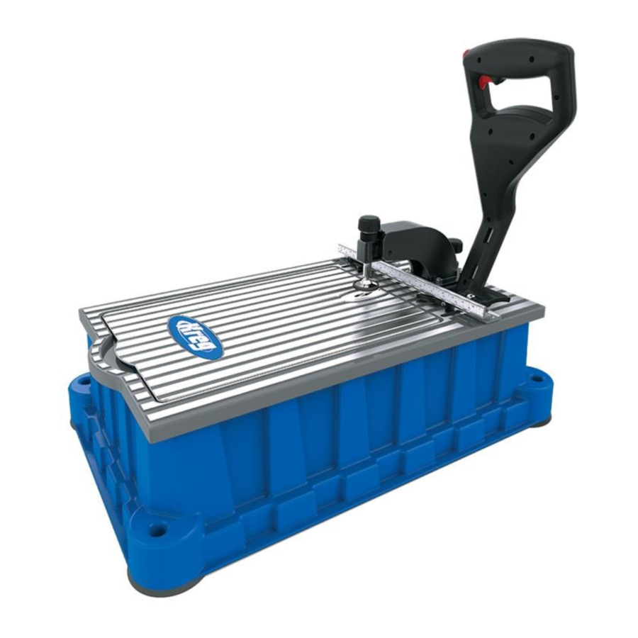
Owning a Foreman gives you all the advantages of a true production pocket-hole machine with the compactness and portability of a bench-top tool. This manual guides you through the steps necessary to adjust your machine and drill pocket holes. In addition to this manual, you may find the following resources helpful:
Kreg Online: To order more pocket-hole screws, view accessories available for your jig, or get help making a particular joint, go to kregtool.com.
Kreg Owner's Community: Sign up as a member, create your own page, view other members' projects, post photos of your projects, view how-to videos, and participate in forums by going to kregjig.ning.com.
Kreg YouTube Channel: For project, product, and tip videos, visit youtube.com/user/kregtoolcompany.
Kreg on Facebook: Connect with Kreg on Facebook to share your projects and get inspiration from our fans and friends at facebook.com/kregJig.
Parts


- Control arm
- Arm lock
- Machine base
- Handles
- Vacuum port
- Self-tapping screws
- Vacuum shroud
- Truss-head machine screws
- Hose clamps
- Vacuum hose
- Access panel
- Machine top
- 3mm hex wrench
- Panel levelers
- ¼-turn fence-lock handles
- Fence
- Fence-lock screws
- Fence-lock bases
- UK plug converter
- Fuse holder
- Workpiece thickness marks
- Drill bit
- Drilling-depth stop knob
- Drilling-depth setting block
- Drill guide (Standard guide included)
- Depth-stop jam nut
- Clamp-arm housing
- Clamp pad
- Clamp adjustment knob
- Clamp jam nut
- Clamp arm
- Access panel lock
- Switch lock-out button
- Switch
- Workpiece stops
- Center-reading measuring tape
- #2 square driver bit 152mm long
- Accessory tray
- Wrench holder
- Foot
- Mounting hole
- Panel support
- Link-release pin
- Motor
- Guide rods
- Quick-change chuck
- Motor link
- Hinge pivots
- Pivot sockets
- Drill-guide set screw
Assembly

To reduce the risk of serious personal injury, turn tool off and disconnect tool from power source before opening the access cover, making any adjustments, or removing or installing attachments or accessories.
Release the control arm
Push down on the control arm (1), release the arm lock (2) at the back of the machine base (3), and guide the control arm to the fullup position. Do not let the arm snap into the full-upright position. For transportation and storage, push down on the control arm and engage the arm lock.
ATTENTION Never lift or carry the machine by the control arm.
Always use the handles (4) at the front and rear of the machine.
TTENTION Remove the drill bit from the machine after use or when storing it.

Install the chip-removal system
The Foreman is supplied with a chip-removal system that includes a 32mm vacuum port (5) and self-tapping screws (6), vacuum shroud (7) and machine screws (8), hose clamps (9), and vacuum hose (10). In addition to helping keep your work area clean, efficient chip removal speeds drilling time and reduces heat build-up, extending the life of your drill bit. A Foreman with the chip-removal system installed must be connected to a shop vacuum when in use. Not connecting the chip-collection system to a shop vacuum causes chips to collect in the hose and vacuum shroud and eventually clog the drill bit. The Foreman can be used without the chip-collection system in place. If you install the system and find that you must use your Foreman without a shop vacuum, simply disconnect the vacuum hose from the vacuum shroud.
To install the chip-removal system, turn the Foreman onto one side and from the inside of the machine base (3), insert the vacuum port (5) into the hole in the back of the base and secure it from the outside with two self-tapping screws (6). Fasten the vacuum shroud (7) to the machine with four truss-head machine screws (8).
Slip the hose clamps (9) over the ends of the vacuum hose (10) and slip the vacuum hose ends onto the vacuum port and vacuum shroud. To make it easy to disconnect the vacuum hose from the vacuum shroud when working through the access panel (11), orient the front hose clamp with the screw head facing the front of the machine. Tighten the clamps and turn the Foreman upright.

Level the access panel

The access panel should be aligned flush with the machine top at the factory. If it needs adjustment, use the following
Place the machine on saw horses so you have access to the bottom of the machine. Lay a straight edge across the machine top (12) and access panel (11). Use the 3mm hex wrench (13) supplied with the machine to turn the panel levelers (14).

Adjust the fence-lock pressure
Rotate the ¼-turn fence-lock handles (15) clockwise (locked position). If the fence (16) can be moved with moderate pressure, tighten the fence-lock screws (17). Rotate the handles counterclockwise (unlocked position) and verify that the fence moves freely.
Should it ever be necessary to disassemble the fence locks, the fence-lock bases (18) must be oriented with the flat area indicated in the drawing facing the fence.

Install the plug converter

Open the hinged UK plug converter (19) cover. Position the two-pin plug that is molded onto the power cord in the converter, snapping the pins into the terminal clips.

Close the converter cover and secure it by tightening the captured machine screw located between the horizontal plug blades.

The converter features a replaceable fuse. To replace the fuse, pry the fuse holder (20) out of the converter base with a small screwdriver. Position a new fuse in the holder and press the holder into the converter base, making sure the holder is fully seated.
Operation
To create strong joints, you'll adjust machine settings to match the thickness of the workpiece and the length of the screw. The Foreman makes this easy, in just four simple steps:
Do not reach inside the machine base from the bottom when the machine is connected to power.
- Position the Fence for Workpiece Thickness
For a strong joint, the pocket screw should exit at the center of the workpiece thickness. This is accomplish this by adjusting the fence position.
Unlock the fence (16) by rotating the fence-lock handles (15) counterclockwise. Align the rear edge of the fence with the workpiece thickness marks (21) cast into the machine top (12) that correspond to your workpiece thickness. Rotate the handles clockwise to lock the fence in place.
![warning]() ATTENTION When drilling pocket holes in ½" [13mm]-thick material using the optional Micro Pocket™ drill guide and drill bit, the rear edge of the fence must be positioned ⅛" [3mm] behind the lines marked ½" that are cast into the machine top. This produces a pocket hole deep enough to fully seat a ¾" [19mm]-long panhead pocket screw and allows plugging with a Micro plug.
ATTENTION When drilling pocket holes in ½" [13mm]-thick material using the optional Micro Pocket™ drill guide and drill bit, the rear edge of the fence must be positioned ⅛" [3mm] behind the lines marked ½" that are cast into the machine top. This produces a pocket hole deep enough to fully seat a ¾" [19mm]-long panhead pocket screw and allows plugging with a Micro plug.

- Choose a Screw
Kreg offers a complete line of pocket screws for every workpiece thickness and type. Use this chart to select the correct screw length. All Kreg pocket screws are available at your Kreg dealer or online at www.kregtool.com.
Coarse Thread
![]()
Due to the large diameter and thread pitch, our #8 coarse-thread screws offer a strong hold in softwoods and composite materials such as plywood, particleboard, and MDF.
Fine Thread
![]()
Because the smaller diameter and thread pitch of our #7 fine-thread screws reduce the chance of splitting the material, we recommend them for hardwoods.Screw Length Selection Guide Material Thickness Screw Length 1⁄2" [13 mm]* 1" [25 mm]†3⁄4" [19 mm]†† 5⁄8" [16 mm] 1" [25 mm] 3⁄4" [19 mm] 11⁄4" [32 mm] 7⁄8" [22 mm] 11⁄2" [38 mm] 1" [25 mm] 11⁄2" [38 mm] 11⁄8" [29 mm] 11⁄2" [38 mm] 11⁄4" [32 mm] 2" [51 mm] 13⁄8" [35 mm] 2" [51 mm] 11⁄2" [38 mm] 21⁄2" [64 mm]
*Panhead pocket screw recommended.
![]()
†For standard Drill Guide
††For optional Micro Drill Guide only
![]()
Note: Screw length is measured from bottom of the head to the tip of the screw. - Set the drilling depth
*optional accessoriesUsing the Drilling-Depth Setting Block Drill Guide & Bit Material Thickness Screw Length Setting Block Step Micro* [13mm] [19mm] ¾" Micro* & Standard [16mm-29mm] [25mm, 32mm, 38mm] 1", 1¼", 1½" Standard [32mm-35mm] [51mm] 2" Standard & HD* [38mm] [64mm] 2½"
Pull the control arm (1) down, advancing the drill bit (22) until the tip touches the fence (16). If necessary, turn the drilling-depth stop knob (23) counterclockwise. Return the control arm to the full-up position, retracting the bit.
Place the drilling-depth setting block (24) against the fence with the screw-length marks facing up. Center the block step that corresponds to the length of screw you'll be using on the drill guide (25). Pull down on the control arm, inserting the drill-bit pilot tip into the hole in the step. With the drill-bit shoulder against the block step, turn the drillingdepth stop knob (23) clockwise until it stops. Tighten the depth-stop jam nut (26) against the base of the clamp-arm housing (27). Return the control arm to the full-up position.
![warning]() ATTENTION
ATTENTION
When re-locking the control arm for transportation or storage, turn the depth-stop knob counterclockwise to allow the arm to return to the full-down position.
![]()
Keep hands away from the rotating drill bit and workpiece clamp area when operating the machine.

- Adjust the workpiece clamp
Raise the control arm (1) to the full-up position. Place the workpiece against the fence (16) and under the clamp pad (28). Turn the clamp adjustment knob (29) clockwise until the clamp pad contacts the workpiece. Now turn the knob counterclockwise one-half turn. Tighten the clamp jam nut (30) against the clamp arm (31). The clamp is now positioned so lowering the control arm applies sufficient pressure to secure the workpiece before the drill bit enters the wood.

Drilling pocket holes
![]()
Before connecting the machine to power, make sure the access panel is closed and locked. To lock the panel, turn the access panel lock (32) clockwise with the 3mm hex wrench (13).
![]()
Keep hands away from the rotating drill bit and workpiece clamp area when operating the machine.
When using the chip-collection system, connect a shop vacuum to the vacuum port (5) and turn it on. Hold the workpiece securely against the fence (16) with the pocket-hole location centered on the drill guide (25). Depress the switch lock-out button (33) on the control arm (1) and pull the switch (34), turning on the drill motor. Let the motor reach full speed and pull the control arm down in a smooth motion until the depth stop makes contact. Return the control arm to the full-up position and release the switch.

Pocket-hole placement
In addition to the proper machine settings, proper spacing of pocket holes in the workpiece is important for making a strong joint. For narrow parts such as rails, stiles and frames, locate pocket holes 10mm to 13mm from each edge. Shaded lines on the measuring tape indicate this offset, eliminating the need to mark pocket-hole locations.
Simply align the edge of your workpiece with the shaded line and drill. For wide parts such as panels and table tops, place the first pocket hole 50mm from the edge and every 150mm on center after that.


Mitered Corners
Two pocket holes with our recommended minimum spacing of 14mm center-to center fit entirely on the face of a 19mm-thick board at least 60mm wide. Simply set up the machine for 19mm-thick stock. Then with the mitered end of the workpiece against the fence, drill one hole 11mm from the miter heel and a second hole 60mm from the miter toe.
You also can drill one pocket hole on each side of a miter joint rather than drilling both holes on the same side.

Workpiece stops
ATTENTION
A workpiece stop can be used on either side of the drill guide by sliding it out of the fence T-slot, flipping it over so the open end of the stop arm faces center, and reinstalling it in the T-slot.
Loosen the socket-head bolt on the workpiece stop (34) with the 3mm hex wrench (13), slide the stop to the desired location, and tighten the bolt. Keeping the fence (16) centered side to side allows you to use the center-reading measuring tape (36) to position the stops. Override a stop by placing the workpiece over the stop, pressing the spring-loaded stop arm into the stop body.
Each stop arm can be held in the retracted position by pressing the arm into the stop body and then sliding it toward the socket-head bolt that secures the stop in the fence. The notch in the arm provides a grip point. To reactivate the stop arm, slide it away from the bolt.

Accessory storage
You can store the #2 square driver bit (37), drilling-depth setting block (24), and optional Micro and HD drill guides and bits in the accessory tray (38) located under the access panel (11). To keep the hex wrench (13) accessible for locking and unlocking the access panel and making other adjustments, insert the long end of the wrench into the wrench holder (39) in the left front foot (40).

Secure mounting
For flexibility in securing your Foreman to a work surface, the foot (40) at each corner of the machine base features a flat surface for temporarily clamping the machine to a work bench as well as a mounting hole (41) for attachment with a bolt or screw.

Switch lock-out
To prevent unauthorized use of the machine, a hole through the switch (34) allows it to be locked in the off position with a padlock (not included).

Replacing a drill bit or installing a drill bit and drill-guide set
ATTENTION
Use the appropriate procedure below when replacing a drill bit or installing the optional Micro or HD drill bits and drill guides.
Drill-bit edges are sharp. Wear gloves when replacing or changing the drill bit.
To protect the workpiece stops (35) when opening the access panel (11), release the fence-lock handles (15) and move the fence (16) all the way back. Turn the clamp adjustment knob (29) counterclockwise to raise the clamp pad (28). Unlock the access panel using the 3mm hex wrench (13), open the panel and engage the panel support (42). Remove the link-release pin (43) and slide the motor (44) off the guide rods (45).
To replace the drill bit (22), pull the quick-change chuck (46) collar forward and remove the drill bit. Insert the new drill bit hex shank into chuck, and release the collar. Slide the motor onto the guide rods, inserting the drill bit into the drill guide (25). Align the motor link (47) with the link hole on the motor, and insert the link-release pin. Disengage the access panel support and close and lock the panel.
When switching to the optional Micro or HD drill and guide, change the drill bit as instructed above. Then disconnect the vacuum hose (10) from the vacuum shroud (7). Lift the access panel off the machine, disengaging the hinge pivots (48) on the access panel from the pivot sockets (49) on the machine top (12).
Place the access panel upside down on a flat surface (for example, a tablesaw table). Loosen the drill-guide set screw (50) with the 3mm hex wrench (13) and remove the drill guide. Firmly holding the access panel against the flat surface, slide the new drill guide into the opening, rotate it so the angled face is against the flat surface, and tighten the set screw.
Install the access panel on the machine and engage the panel support. Reconnect the vacuum hose to the vacuum shroud. Slide the motor onto the guide rods, inserting the drill bit into the drill guide. Connect the motor link (47) to the motor with the link-release pin and close and lock the panel.

Maintenance
To reduce the risk of serious personal injury, turn tool off and disconnect tool from power source before opening the access panel, making any adjustments, or removing or installing attachments or accessories.
- Keep the motor clean and the machine base free of wood chips and dust. When used without a shop vacuum, routinely remove waste material from inside the cabinet or mount the machine on an open stand that prevents waste-material accumulation.
- Periodically lubricate the guide rods with a dry-film lubricant. A dry film lubricant will not collect wood chips and dust and will extend the life of the bearings and the guide rods. The motor link and linkage associated with the clamping mechanism should be lubricated periodically to ensure free movement.
- Use a sharp drill bit. You can drill between 4,000 and 5,000 holes in oak before replacing the bit. Adjust your replacement schedule for your settings and the material that you are drilling. Keeping the drill bit clean and free of pitch, resin, and glue significantly extends the life of the bit. Periodically clean the drill bit with a cutting-tool cleaner and apply a dry lubricant. Even a dirty drill bit can be very sharp, so exercise caution when handling the cutting edges.
ATTENTION
When replacing the drill bit, use only Kreg replacement bits.
If the power supply cord is damaged, do not attempt to repair it. A damaged cord must be replaced by a specially prepared cord available through the Kreg service organization.
Motor service
To ensure product safety and reliability, all motor repairs should be performed by the Kreg Tool Company factory service center. Call Kreg Customer Service (1.800.447.8638) for return authorization and shipping instructions.
Replacement parts
For a diagram and list of replacement parts and assemblies, go to www.kregtool.com and view the online version of this manual.
Tips
Tips to reduce splitting
- Test Pieces
Test the joint with scrap pieces cut from the same stock as your final workpiece. - Make sure you're using Kreg Screws
Kreg screws feature sharp, self-tapping tips that slice through the wood fibers instead of forcing them apart. - Use the Right Screw Type
Use fine-thread screws in hardwood. These #7 screws displace less wood than the #8 coarse-thread screws used for softwood, plywood, MDF, and particleboard.
- Screw it In, Back it Out
Drive the screw half-way in, back it out to clear excess wood fibers from the hole, and then drive the screw all the way in. - Reduce Friction
Apply bee's wax or other lubricant to the screw to reduce the friction as the screw enters the workpiece - Clamp Correctly
Center the pads of your Kreg Face Clamp™ on the joint line with the large clamp pad on the face side (opposite the pocket holes) of the joint. Adjust the clamp to apply enough pressure to keep the workpieces flush and stable but not so tight to make clamping and unclamping difficult.
Optional Accessories
Because accessories, other than those offered by Kreg, have not been tested with this product, use of such accessories with this tool could be hazardous. To reduce the risk of injury, only Kreg recommended accessories should be used with this product. Recommended accessories for use with your tool are available at extra cost from your distributor or local service center. The following accessories are available for the Kreg Foreman DB210-EUR from your Kreg dealer or online at www.kregjig.com.
Micro Pocket™ Drill Guide and Drill Bit ITEM# DB210-MBB

With a hole diameter 25% smaller than our standard pocket hole, the Micro Pocket™ Drill Guide lets you create compact pocket holes in thin stock, and tight repair applications.
HD Drill Bit

ITEM# DB210-HDB
Replacement drill bit for the Foreman DB210-EUR
Kreg Jig® HD Drill Guide and Drill Bit

ITEM# DB210-HDBB
Designed for use with "2-by" material, this heavy-duty system drill holes for #14 x 21⁄2" pocket screws.
Kreg Face Clamps™

Item# KHC-PREMIUM (75mm reach),
Item# KHC-LARGE (150mm reach),
Item# KHC-XLARGE (250mm reach)
With a choice of 75mm-, 150mm-, and 250mm reach, there's a Kreg Face Clamp™ that meets your needs.
www.kregtool.com
1.800.447.8638
Documents / Resources
References
![kregtool.com]() Welcome to Kreg Tool
Welcome to Kreg ToolKreg Owners' Community
![youtube.com]() Kreg Tool - YouTube
Kreg Tool - YouTube![www.kregtool.com]() Welcome to Kreg Tool
Welcome to Kreg Tool![www.kregjig.com]() Welcome to Kreg Tool
Welcome to Kreg Tool
Download manual
Here you can download full pdf version of manual, it may contain additional safety instructions, warranty information, FCC rules, etc.
Advertisement


Need help?
Do you have a question about the FOREMAN DB210-EUR and is the answer not in the manual?
Questions and answers