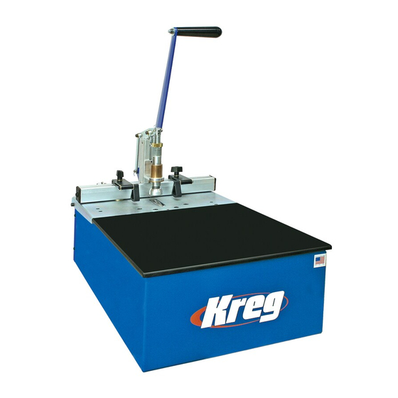
Kreg DB110 Instructional Manual

Kreg DB110 Instructional Manual

Foreman
Hide thumbs Also See for DB110:

Advertisement

FOREMAN
R
R
INSTRUCTIONAL MANUAL
DB55 Pneumatic/DB110 Electric Models
Item# DB110
Item# DB55
Patents pending.
6/2010
DB5305
Rev C

Advertisement

Table of Contents
loading
Need help?

Need help?

Do you have a question about the DB110 and is the answer not in the manual?

Questions and answers

Subscribe to Our Youtube Channel

Summary of Contents for Kreg DB110

  • Page 1 FOREMAN INSTRUCTIONAL MANUAL DB55 Pneumatic/DB110 Electric Models Item# DB110 Item# DB55 Patents pending. 6/2010 DB5305 Rev C...
  • Page 2: Table Of Contents

    This machine was designed for specifi c applications only. Kreg strongly recommends that this machine NOT be modifi ed and/or used for any application other than for which it was designed. If you have any questions relative to its application, DO NOT use the Machine until you have written Kreg Tool and we have advised you.
  • Page 3 Acrylic Top Must Be Secured (DB55 & DB110) Do not operate this machine without the acrylic top positioned correctly and secured with the two provided lock-down screws. Running the machine without the top in place and properly secured increases your chance of injury and is not recommended under any circumstance.
  • Page 4 • This system was designed for certain applications only. Kreg strongly recommends that this system NOT be modifi ed and/or used for any application other than for which it was designed. If you have any questions relative to its application, DO NOT use the machine until you have written, phoned, or e-mailed Kreg Tool and have been advised accordingly.
  • Page 5 • Use recommended accessories only. Use of any additional accessories (add-ons) is strictly at your own risk. This machine was designed with only the use of Kreg certifi ed parts in mind. Use of uncertifi ed accessories may be hazardous.
  • Page 6 à l’opérateur. • Ce système a été conçu pour certaines applications seulement. Il est fortement recommandé par Kreg de NE PAS modifi er et/ou utiliser ce système pour des applications autres que celles pour lesquelles il a été conçu. Si vous avez des questions concernant son application, N’UTILISEZ PAS la machine avant d’avoir écrit, appelé...
  • Page 7: Safety Guidelines

    • Utilisez uniquement les accessoires recommandés. L’utilisation d’accessoires supplémentaires (extensions) est strictement à vos propres risques. Cette machine a été conçue uniquement en fonction de pièces certifi ées Kreg. L’emploie d’accessoires non certifi és peut s’avérer dangereux.
  • Page 8: Assembly Instructions - Db110

    Assembly Instructions - DB110 Electric Semi-Automatic Electric Foreman DB110 Assembly Fig. 3A Entirely electric, no compressed air needed. Motor rated at 3/4-HP and 8-amps Assemble the Handle (Fig. 3A) The Handle for the Foreman is disconnected for shipping purposes. The handle is shipped with two nut and bolt sets installed fi nger tight in the Handle and Operator Assembly.
  • Page 9: Assembly Instructions - Db55

    Assembly Instructions - DB55 Pneumatic Fig. 4A Semi-Automatic Pneumatic Foreman DB55 Assembly Assemble the Handle (Fig. 4A) The Handle for the Foreman is disconnected for shipping purposes. The handle is shipped with two nut and bolt sets installed fi nger tight in the Handle and Operator Assembly.
  • Page 10: General Operations/Maintenance

    DB110 Electric - General Operation/Maintenance Fig. 5A Semi-Automatic Electric Foreman DB110 Operation Entirely electric, no compressed air needed. Motor rated at 3/4-HP and 8-amps GENERAL OPERATION (Fig. 5A) To operate the Electric FOREMAN, fi rst place a workpiece under the clamping pad. Make sure that the clamping pad extends no more than 1/8”...
  • Page 11: Db110 (Electric Model)

    DB110 Electric - Adjustments Adjusting the EZ DB Fence Setting Fig. 6A The Fence can be adjusted to align the pocket hole to the center of material of different thicknesses. When adjusting the Fence make sure that the Fence remains perpendicular to the Guide Plate. A Reference Scale has been provided to approximate the fence setting for 1/2”, 3/4”,...
  • Page 12: Adjusting The Drill Bit Depth Stop/Clamping Pad Height

    DB110 Electric - Adjustments Adjusting the Drill Bit Depth Stop Fig. 7A (Fig. 7A) A Drill Bit Depth Stop is provided to stop the Drill Bit forward motion. Before adjusting the Drill Bit Depth Stop make certain your machine is DISCONNECTED from the ELECTRICAL SUPPLY. Without an electrical supply you can be certain the machine will not accidentally engage while you are performing this adjustment.
  • Page 13: Swing Stops/Changing The Drill Bit

    DB110 Electric - Adjustments Semi-Automatic Electric Foreman DB110 Operation Fig. 8A ADJUSTMENTS (Cont’) Swing Stops (Fig. 8A) Two Swing Stops are provided to assist in drilling pocket holes in the same location on multiple workpieces of the same dimension. When the Swing Stop is not used, it will pivot out of the way to allow the workpiece to slide underneath and rest against the fence.
  • Page 14: Db55 (Pneumatic Model)

    DB55 Pneumatic - General Operation/Maintenance Fig. 9A Semi-Automatic Pneumatic Foreman DB55 Operation GENERAL OPERATION (Fig. 9A) To operate the Pneumatic FOREMAN, fi rst place a workpiece under the clamping pad. Make sure that the clamping pad extends no more than 1/4” above the workpiece in the unclamped state. If more than a 1/4”...
  • Page 15: Adjusting The Ez Db Fence

    DB55 Pneumatic - Adjustments Adjusting the EZ DB Fence Setting Fig. 10A The Fence can be adjusted to align the pocket hole to the center of material of different thicknesses. When adjusting the Fence make sure that the Fence remains perpendicular to the Guide Plate. A Reference Scale has been provided to approximate the fence setting for 1/2”, 3/4”, and 1-1/2”...
  • Page 16: Adjusting The Drill Bit Depth Stop/Clamping Cylinder Height/Automatic Lubricator

    DB55 Pneumatic - Adjustments Adjusting the Drill Bit Depth Stop Fig. 11A (Fig. 11A) A Drill Bit Depth Stop is provided to stop the Drill Bit forward motion. Before adjusting the Drill Bit Depth Stop make certain your machine is DISCONNECTED from the AIR SUPPLY. Cycle the machine via the Handle to remove air from the system.
  • Page 17: Swing Stops/Changing The Drill Bit

    DB55 Pneumatic - Adjustments Fig. 12A Semi-Automatic Pneumatic Foreman DB55 Operation ADJUSTMENTS (Cont’) Swing Stops (Fig. 12A) Two Swing Stops are provided to assist in drilling pocket holes in the same location on multiple work pieces of the same dimension. When the Swing Stop is not used, it will pivot out of the way to allow the work piece to slide underneath and rest against the fence.
  • Page 18: Warranty

    This is Kreg Tool Company’s sole warranty. Any and all other warranties which may be implied by law, including any warranties for merchantability or fi tness for a particular purpose, are hereby limited to the duration of this warranty. Kreg Tool Company shall not be liable for any loss, damage or expense directly or indirectly related to the use of its products or from any other cause or for consequential damages (including without limitation, loss of time, inconvenience, and loss of production).
  • Page 19: Notes

    Notes...
  • Page 20 Notes Kreg Tool Company, 201 Campus Drive, Huxley, IA 50124 800.447.8638 • www.kregtool.com...

This manual is also suitable for:

Db55

Table of Contents

Save PDF