Axis P5655-E Manual
- User manual (63 pages) ,
- Installation manual (34 pages) ,
- Preventive maintenance instructions and checklist (12 pages)
Advertisement
- 1 Product overview
- 2 Find the device on the network
- 3 Setup
-
4
Troubleshooting
- 4.1 Reset to factory default settings
- 4.2 Check the current firmware
- 4.3 Upgrade the firmware
- 4.4 Firmware upgrade failure
- 4.5 The device is located on a different subnet
- 4.6 The IP address is being used by another device
- 4.7 Cannot log in
- 4.8 The IP address has been changed by DHCP
- 4.9 Certificate error when using IEEE 802.1X
- 4.10 The device is accessible locally but not externally
- 4.11 Multicast H.264 only accessible by local clients
- 4.12 No multicast H.264 displayed in the client
- 5 Specifications
- 6 Documents / Resources
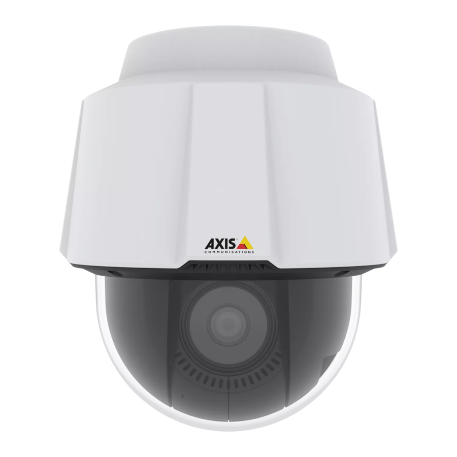
Product overview
NOTICE
Make sure the dome is attached in operation mode, otherwise focus may be affected.

- SD memory card slot
- Control button
- Status LED indicator
- Power button
- Network connector (PoE+)
- Mounting screws (3)
- Ground screw
- Multi-connector with cover (Do not remove the cover unless an I/O-cable is connected)
- Hook for safety wire
- Dome
Find the device on the network
To find Axis devices on the network and assign them IP addresses in Windows®, use AXIS IP Utility or AXIS Device Manager. Both applications are free and can be axis.com/support.
For more information about how to find and assign IP addresses, see the document How to assign an IP address and access your device on the device page at axis.com.
Access the device
- Open a browser and enter the IP address or host name of the Axis device.
If you have a Mac computer (OS X), go to Safari, click on Bonjour and select the device from the drop-down list. To add Bonjour as a browser bookmark, go to Safari > Preferences.
If you do not know the IP address, use AXIS IP Utility or AXIS Device Manager to find the device on the network. - Enter the username and password. If you access the device for the first time, you must set the root password. SeeSet a secure password for the root account .
- The live view page opens in your browser.
Secure passwords

Axis devices send the initially set password in clear text over the network. To protect your device after the first login, set up a secure and encrypted HTTPS connection and then change the password.
The device password is the primary protection for your data and services. Axis devices do not impose a password policy as they may be used in various types of installations.
To protect your data we strongly recommend that you:
- Use a password with at least 8 characters, preferably created by a password generator.
- Don't expose the password.
- Change the password at a recurring interval, at least once a year.
Set a secure password for the root account
The default administrator username is root. If the password for root is lost, reset the device to factory default settings.
- Type a password. Follow the instructions about secure passwords. SeeSecure passwords .
- Retype the password to confirm the spelling.
- ClickCreate login. The password has now been configured.
Setup
Need more help?
You can access the built-in help from the device's webpage. The help provides more detailed information on the device's features and their settings.

Image quality
Adjust the focus faster with focus recall areas
To save the focus settings at a specific pan/tilt range, add a focus recall area. Each time the camera moves into that area it recalls the previously saved focus. It's enough to cover half of the focus recall area in the live view.
We recommend the focus recall feature in the following scenarios:
- When there is a lot of manual operation in live view, for example with a joystick.
- Where PTZ preset positions with manual focus are not efficient, for example movements where the focus setting changes continuously.
- In low-light scenarios, where the autofocus is challenged by the lighting conditions.
- The focus recall overrides the camera's autofocus at the specific pan/tilt range.
- A preset position overrides the focus setting saved in the focus recall area.
- The maximum number of focus recall areas is 20.
Create a focus recall area
- Pan, tilt, and zoom into the area where you would like to have focus.
As long as the focus recall button shows a plus![]() , you can add a focus recall area in that position.
, you can add a focus recall area in that position. - Adjust the focus.
- Click the focus recall button.
Delete a focus recall area
- Pan, tilt, and zoom into the focus recall area you want to delete.
The focus recall button toggles to minus when the camera detects a focus recall area.![]()
- Click the focus recall button.
Handle scenes with strong backlight
Dynamic range is the difference in light levels in an image. In some cases the difference between the darkest and the brightest areas can be significant. The result is often an image where either the dark or the bright areas are visible. Wide dynamic range (WDR) makes both dark and bright areas of the image visible.
- Go to Settings > Image > Wide dynamic range.
- If required, turn on WDR.
- Use the Local contrast slider to adjust the amount of WDR.
Image without WDR.

Image with WDR.


Note
WDR may cause artifacts in the image.
Find out more about WDR and how to use it at axis.com/web-articles/wdr.
Hide parts of the image with privacy masks
Create a privacy mask to hide a part of the image:
- Go to Settings > Privacy mask.
- Click New.
Streaming and storage
Bitrate control
By setting the bitrate control you can manage the bandwidth consumption for your video stream.
Variable bitrate (VBR)
With variable bitrate the bandwidth varies based on the level of activity in the scene. The more activity in the scene, the more bandwidth is required. This option guarantees that image quality is constant but requires storage margins.
Maximum bitrate (MBR)
The maximum bitrate option allows you to set a target bitrate value to be able to handle system bitrate limitations. To keep the instantaneous bitrate below the specified target bitrate, there may be a decrease in image quality or the frame rate may decrease. You have the option to prioritize either image quality or frame rate. It is recommended to configure the target bitrate higher than the expected bitrate to have margins for additional complexity that needs to be captured.
Average bitrate (ABR)
With average bitrate, the bitrate is automatically adjusted over a longer timescale to meet the specified target and provide the best quality on the video stream based on available storage. Image quality is decreased uniformly. You can still get good image quality when there is activity in the scene. The average bitrate option allows you to define the total storage required to store the video stream for a specified amount of time (retention time) when image quality is adjusted to meet the specified target bitrate. Specify the average bitrate settings in one of the following ways:
- Set the target bitrate and the retention time to calculate the estimated storage need.
- Use the target bitrate calculator to calculate the average bitrate, based on available storage and desired retention time.
You have also the option to turn on maximum bitrate to specify a bitrate limit.
Video compression formats
Decide which compression method to use based on your viewing requirements, and on the properties of your network. The available options are:
Motion JPEG
Motion JPEG, or MJPEG, is a digital video sequence that is made up of a series of individual JPEG images. These images are then displayed and updated at a rate sufficient to create a stream that shows constantly updated motion. For the viewer to perceive motion video the rate must be at least 16 image frames per second. Full motion video is perceived at 30 (NTSC) or 25 (PAL) frames per second.
The Motion JPEG stream uses considerable amounts of bandwidth, but provides excellent image quality and access to every image contained in the stream.
H.264 or MPEG-4 Part 10/AVC
Note
H.264 is a licensed technology. The Axis product includes one H.264 viewing client license. To install additional unlicensed copies of the client is prohibited. To purchase additional licenses, contact your Axis reseller.
H.264 can, without compromising image quality, reduce the size of a digital video file by more than 80% compared to the Motion JPEG format and by as much as 50% compared to the MPEG-4 standard. This means that less network bandwidth and storage space are required for a video file. Or seen another way, higher video quality can be achieved for a given bitrate.
H.265 or MPEG-H Part 2/HEVC
Note
H.265 is licensed technology. The Axis product includes one H.265 viewing client license. To install additional unlicensed copies of the client is prohibited. To purchase additional licenses, contact your Axis reseller.
Reduce bandwidth and storage
If you reduce the bandwidth it can result in loss of details in the picture.
- Go to live view and select H.264.
- Go to Settings > Stream.
- Do one or more of the following:
- Turn on the Zipstream functionality and select the desired level.
Note
The zipstream settings are used for both H.264 and H.265.
- Turn on dynamic GOP and set a high GOP length value.
- Increase the compression.
- Turn on dynamic FPS.
Note
Web browsers do not support H.265 decoding. Use a video management system or application supporting H.265 decoding.
Add audio to your recording
Edit the stream profile which is used for the recording:
- Go toSettings > Stream and click Stream profiles.
- Select the stream profile and clickAudio.
- Select the checkbox and selectInclude.
- ClickSave.
- ClickClose.
Overlays
Overlays are superimposed over the video stream. They are used to provide extra information during recordings, such as a timestamp, or during product installation and configuration. You can add either text or an image.
Show the pan or tilt position as a text overlay
You can show the pan or tilt position as an overlay in the image.
- Go to Settings > Overlay and click Create overlay.
- Select Text and click Create.
- In the text field, type #x to show the pan position. Type #y to show the tilt position.
- Choose appearance, text size, and alignment.
- Include the text overlay.
- The current pan and tilt positions show up in the live view image and in the recording.
Pan, tilt, and zoom (PTZ)
Limit the pan, tilt, and zoom movements
If there are parts of the scene that you don't want the camera to reach, you can limit the pan, tilt, and zoom movements. For example, you want to protect the privacy of residents in an apartment building, which is located close to a parking lot that you intend to monitor. To limit the movements, go to Settings > PTZ > Limits.
Guard tours
A guard tour displays the video stream from different preset positions either in a predetermined or random order, and for configurable periods of time. Once started, a guard tour continues to run until stopped, even when there are no clients (web browsers) viewing the images.
Create a guard tour with preset positions
A guard tour displays the video stream from different preset positions either in a predetermined or random order, and for configurable periods of time.
- Go to Settings > PTZ > Guard tours.
- Click+.
- Select Preset position.
- To edit the guard tour's properties, click
![]() .
. - Type a name for the guard tour and specify the pause length in minutes between each tour.
- If you want the guard tour to go to the preset positions in a random order, turn on Shuffle.
- Click Done.
- Click Add to add the preset positions that you want in your guard tour.
- Click Done to exit the guard tour settings.
- To schedule the guard tour, go to System > Events.
Events
Set up rules and alerts
You can create rules to make your device perform an action when certain events occur. A rule consists of conditions and actions. The conditions can be used to trigger the actions. For example, the device can start a recording or send an email when it detects motion, or show an overlay text when it records.
Direct the camera to a preset position when the camera detects motion
This example explains how to set up the camera to go to a preset position when it detects motion in the image.
Make sure the AXIS Video Motion Detection application is running:
- Go to Settings > Apps > AXIS Video Motion Detection.
- Start the application if it is not already running.
- Make sure you have set up the application according to your needs.
Add a preset position:
Go to Settings > PTZ and set where you want the camera to be directed by creating a preset position.
Create a rule:
- Go to Settings > System > Events > Rules and add a rule.
- Type a name for the rule.
- In the list of conditions, select a video motion detection condition under Application.
- From the list of actions, select Go to preset position.
- Select the preset position you want the camera to go to.
- Click Save.
Direct the camera and open the lock to a gate when someone is nearby
This example explains how to direct the camera and open a gate when someone wants to enter during daytime. This is done by connecting a PIR detector to the product's input port and a switch relay to the product's output port via the multicable.
Required hardware
- Multicable (sold separately), see Multiconnector.
- Mounted PIR detector
- Switch relay connected to the gate lock, in this case the switch is normally closed (NC)
- Connecting wires
Physical connection
- Remove the plug from the camera's multi-connector and connect the multicable.
- Connect the wires from the PIR detector to the input pin, see Multiconnector.
- Connect the wires from the switch to the output pin, see Multiconnector.
Configure I/O ports
You need to connect the switch relay to the camera from the camera's webpage. First, configure the I/O ports: Set the PIR detector to an input port
- Go to System > I/O ports.
- Select Input in the Port 1 drop-down list.
![]()
- Give the input module a descriptive name, for example "PIR detector".
- To trigger an event whenever the PIR detector senses motion, select Open circuit in the drop-down list.
![]()


Set the switch relay to an output port
- Go toSystem > I/O ports.
- SelectOutput in the Port 2 drop-down list.
![]()
- Give the output module a descriptive name, for example "Gate switch".
- To open the gate whenever an event is triggered, selectClosed circuit in the drop-down list.
![]()


Create the preset position
- Go to Settings > PTZ > Preset positions.
- Create the preset position that covers the entrance of the gate and name it, for example, "Gate entrance".
Create rules
For the camera to open the gate when the PIR detector senses someone nearby, you need to create a rule in the camera:
- Go to Settings > System > Events and add a rule.
- Type a name for the rule, for example "Open gate".
- In the list of conditions, select PIR detector.
- In the list of actions, select Toggle I/O once.
- In the list of ports, select Gate switch.
- Set state to Active.
- Set the duration.
- Click Save.
- Create another rule with the name "Direct the camera to the gate".
- Select the same input signal as before, but as action select the previously created "Gate entrance" preset position.
- Click Save.
Record video when the camera detects loud noises
This example explains how to set up the camera to start recording to the SD card five seconds before it detects loud noise and to stop one minute after.
Turn on audio:
- Set up the stream profile to include audio, see Add audio to your recording.
Turn on audio detection:
- Go to Settings > System > Detectors > Audio detection.
- Adjust the alarm level according to your needs.
Create a rule:
- Go to Settings > System > Events and add a rule.
- Type a name for the rule.
- In the list of conditions, under Audio, select Audio Detection.
- In the list of actions, under Recordings, select Record video.
- Select the stream profile where audio has been turned on.
- Set the prebuffer time to 5 seconds.
- Set the postbuffer time to 60 seconds.
- In the list of storage options, select SD card.
- Click Save.
Zoom in on a specific area automatically with gatekeeper
This example explains how to use the gatekeeper functionality to make the camera zoom in automatically on the license plate of a car that passes through a gate. When the car has passed, the camera zooms out to the home position.
Create the preset positions:
- Go to Settings > PTZ > Preset positions.
- Create the home position that includes the entrance of the gate.
- Create the zoomed-in preset position so that it covers the area in the image where you assume that the license plate will appear.
Create a motion detection profile:
- Go to Settings > Apps and open AXIS Video Motion Detection.
- Create a profile that covers the entrance of the gate and then save the profile.
Create a rule:
- Go to Settings > System > Events and add a rule.
- Name the rule "Gatekeeper".
- In the list of conditions, under Application, select the motion detection profile.
- In the list of actions, under Preset positions, select Go to preset position.
- Select a Video channel.
- Select the Preset position.
- To make the camera wait a while before it returns to the home position, select Home timeout, and set a time.
- Click Save.
Record video when the camera detects impact
Shock detection allows the camera to detect tampering caused by vibrations or shock. Vibrations due to the environment or to an object can trigger an action depending on the shock sensitivity range, which can be set from 0 to 100. In this scenario, someone is throwing rocks at the camera after hours and you would like to get a video clip of the event.
Turn on shock detection:
- Go to Settings > System > Detectors.
- Turn on shock detection, and set a value for the shock sensitivity.
Create a rule:
- Go to Settings > System > Events and add a rule.
- Type a name for the rule.
- In the list of conditions, under Device status, select Shock detected.
- Click+ to add a second condition.
- In the list of conditions, under Scheduled and recurring, select Scheduled event.
- In the list of schedules, selet After hours .
- In the list of actions, under Recordings, select Record video while the rule is active.
- Select a Camera.
- Set the prebuffer time to 5 seconds.
- Set the postbuffer time to 60 seconds.
- Select where to save the recordings.
- Click Save.
Applications
AXIS Camera Application Platform (ACAP) is an open platform that enables third parties to develop analytics and other applications for Axis products. To find out more about available applications, downloads, trials and licenses, go to axis.com/applications.
To find the user manuals for Axis applications, go to axis.com.
Note
- Several applications can run at the same time but some applications might not be compatible with each other. Certain combinations of applications might require too much processing power or memory resources when run in parallel. Verify that the applications work together before deployment.
Troubleshooting
If you can't find what you're looking for here, try the troubleshooting section at axis.com/support.
Reset to factory default settings
Reset to factory default should be used with caution. A reset to factory default resets all settings, including the IP address, to the factory default values.
To reset the product to the factory default settings:
- Press and hold the control button and the power button for 15–30 seconds until the status LED indicator flashes amber. SeeProduct overview .
- Release the control button but continue to hold down the power button until the status LED indicator turns green.
- Release the power button and assemble the product.
- The process is now complete. The product has been reset to the factory default settings. If no DHCP server is available on the network, the default IP address is 192.168.0.90.
- Using the installation and management software tools to assign an IP address, set the password and access the video stream.
It is also possible to reset parameters to factory default through the web interface. Go to Settings > System > Maintenance and click Default.
Check the current firmware
Firmware is the software that determines the functionality of network devices. One of your first actions when troubleshooting a problem should be to check the current firmware version. The latest version may contain a correction that fixes your particular problem.
To check the current firmware:
- Go to the product's webpage.
- Click on the help menu.
![]()
- Click About.
Upgrade the firmware
Preconfigured and customized settings are saved when the firmware is upgraded (provided that the features are available in the new firmware) although this is not guaranteed by Axis Communications AB.
Make sure the cover is attached during upgrade to avoid installation failure.
Make sure the product remains connected to the power source throughout the upgrade process.
Note
When you upgrade the product with the latest firmware in the active track, the product receives the latest functionality available. Always read the upgrade instructions and release notes available with each new release before upgrading the firmware. To find the latest firmware and the release notes, go to axis.com/support/firmware.
- Download the firmware file to your computer, available free of charge at axis.com/support/firmware.
- Log in to the product as an administrator.
- Go to Settings > System > Maintenance. Follow the instructions on the page. When the upgrade has finished, the product restarts automatically.
AXIS Device Manager can be used for multiple upgrades. Find out more at axis.com/products/axis-device-manager.
Technical issues, clues and solutions
If you can't find what you're looking for here, try the troubleshooting section at axis.com/support.
Problems upgrading the firmware
Firmware upgrade failure | If the firmware upgrade fails, the device reloads the previous firmware. The most common reason is that the wrong firmware file has been uploaded. Check that the name of the firmware file corresponds to your device and try again. |
Problems setting the IP address
The device is located on a different subnet | If the IP address intended for the device and the IP address of the computer used to access the device are located on different subnets, you cannot set the IP address. Contact your network administrator to obtain an IP address. |
The IP address is being used by another device | Disconnect the Axis device from the network. Run the ping command (in a Command/DOS window, type ping and the IP address of the device):
|
| Possible IP address conflict with another device on the same subnet | The static IP address in the Axis device is used before the DHCP server sets a dynamic address. This means that if the same default static IP address is also used by another device, there may be problems accessing the device. |
The device cannot be accessed from a browser
Cannot log in | When HTTPS is enabled, ensure that the correct protocol (HTTP or HTTPS) is used when attempting to log in. You may need to manually type http or https in the browser's address field. If the password for the user root is lost, the device must be reset to the factory default settings. See Reset to factory default settings. |
The IP address has been changed by DHCP | IP addresses obtained from a DHCP server are dynamic and may change. If the IP address has been changed, use AXIS IP Utility or AXIS Device Manager to locate the device on the network. Identify the device using its model or serial number, or by the DNS name (if the name has been configured). If required, a static IP address can be assigned manually. For instructions, go to axis.com/support. |
Certificate error when using IEEE 802.1X | For authentication to work properly, the date and time settings in the Axis device must be synchronized with an NTP server. Go to Settings > System > Date and time. |
The device is accessible locally but not externally
To access the device externally, we recommend using one of the following applications for Windows®:
- AXIS Companion: free of charge, ideal for small systems with basic surveillance needs.
- AXIS Camera Station: 30-day trial version free of charge, ideal for small to mid-size systems. For instructions and download, go toa xis.com/products/axis-companion.
Problems with streaming
Multicast H.264 only accessible by local clients | Check if your router supports multicasting, or if the router settings between the client and the device need to be configured. The TTL (Time To Live) value may need to be increased. |
No multicast H.264 displayed in the client | Check with your network administrator that the multicast addresses used by the Axis device are valid for your network. Check with your network administrator to see if there is a firewall preventing viewing. |
| Poor rendering of H.264 images | Ensure that your graphics card is using the latest driver. The latest drivers can usually be the manufacturer's website. |
| Color saturation is different in H.264 and Motion JPEG | Modify the settings for your graphics adapter. Go to the adapter's documentation for more information. |
| Lower frame rate than expected |
|
| Can't select H.265 encoding in live view | Web browsers do not support H.265 decoding. Use a video management system or application supporting H.265 decoding. |
Performance considerations
When setting up your system, it is important to consider how various settings and situations affect the performance. Some factors affect the amount of bandwidth (the bitrate) required, others can affect the frame rate, and some affect both. If the load on the CPU reaches its maximum, this also affects the frame rate.
The following factors are the most important to consider:
- High image resolution or lower compression levels result in images containing more data which in turn affects the bandwidth.
- Rotating the image in the GUI will increase the product's CPU load.
- Removing or attaching the cover will restart the camera.
- Access by large numbers of Motion JPEG or unicast H.264 clients affects the bandwidth.
- Simultaneous viewing of different streams (resolution, compression) by different clients affects both frame rate and bandwidth.
Use identical streams wherever possible to maintain a high frame rate. Stream profiles can be used to ensure that streams are identical. - Accessing Motion JPEG and H.264 video streams simultaneously affects both frame rate and bandwidth.
- Heavy usage of event settings affects the product's CPU load which in turn affects the frame rate.
- Using HTTPS may reduce frame rate, in particular if streaming Motion JPEG.
- Heavy network utilization due to poor infrastructure affects the bandwidth.
- Viewing on poorly performing client computers lowers perceived performance and affects frame rate.
- Running multiple AXIS Camera Application Platform (ACAP) applications simultaneously may affect the frame rate and the general performance.
Specifications
To find the latest version of the product's datasheet, go to the product page at axis.com and locate Support & Documentation.
LED indicators
| Status LED | Indication |
| Unlit | Connection and normal operation. |
| Green | Shows steady green for 10 seconds for normal operation after startup completed. |
| Amber | Steady during startup. Flashes during firmware upgrade or reset to factory default. |
| Amber/Red | Flashes amber/red if network connection is unavailable or lost. |
SD card slot
NOTICE
- Risk of damage to SD card. Do not use sharp tools, metal objects, or excessive force when inserting or removing the SD card. Use your fingers to insert and remove the card.
- Risk of data loss and corrupted recordings. Do not remove the SD card while the product is running. Unmount the SD card from the product's webpage before removal.
This product supports SD/SDHC/SDXC cards.
For SD card recommendations, see axis.com.
Buttons
Control button
The control button is used for:
- Resetting the product to factory default settings. SeeReset to factory default settings.
- Connecting to an AXIS Video Hosting System service. To connect, press and hold the button for about 3 seconds until the status LED flashes green.
Power button
Press and hold the power button to temporarily power the product when the dome cover is removed. The power button is also used with the control button to reset the camera to factory default settings.
Connectors
Network connector
RJ45 Ethernet connector with Power over Ethernet Plus (PoE+).
Multiconnector
Terminal connector for connecting external equipment:
- Audio equipment
- Input/Output (I/O) devices
- AC/DC power supply
When connecting external equipment, a separately sold Axis Multicable C I/O Audio Power 1 m/ 5 m or a separately sold Axis 10-pin Push-pull System Connector is required in order to maintain the product's IP rating. For more information, see Multicable connectors and Axis 10-pin push-pull system connector (sold separately).
Multicable connectors

Multicable overview
- Camera multiconnector
- I/O terminal block
- Audio terminal block
- Power connector
The multicable provides the following connectors:
Power connector - 2-pin terminal block used for power input. The polarity of the cables does not matter. Use a Safety Extra Low Voltage (SELV) compliant limited power source (LPS) with either a rated output power limited to ≤100 W or a rated output current limited to ≤5 A.
![]()
Audio connector - 4–pin terminal block used for audio in and audio line out. This can be connected to a public address (PA) system or an active speaker with a built-in amplifier.

| Function | Pin | Notes |
| Audio In | 1 | Balanced or unbalanced input for a mono microphone or line signal |
| Audio Line Out | 3 | Can be connected to a public address (PA) system or an active speaker with a built-in amplifier |
| GND | 2, 4 | Ground |
I/O terminal connector - Use with external devices in combination with, for example, tampering alarms, motion detection, event triggering, and alarm notifications. In addition to the 0 V DC reference point and power (DC output), the I/O connector provides the interface to:
- Digital output — For connecting external devices such as relays and LEDs. Connected devices can be activated by the VAPIX® Application Programming Interface or from the product's webpage.
- Digital input — For connecting external devices that can toggle between an open and closed circuit, for example PIR detectors, door/window contacts, and glass break detectors.

| Function | Pin | Notes | Specifications |
| 0 V DC (-) | 1 | 0 V DC | |
| DC output | 2 | Can be used to power auxiliary equipment. Note: This pin can only be used as power out. | 12 V DC Max load =50 mA |
| Configurable (Input or Output) | 3–6 | Digital input – Connect to pin 1 to activate, or leave floating (unconnected) to deactivate. | 0 to max 30 V DC |
| Digital output – Internally connected to pin 1 (DC ground) when active, and floating (unconnected) when inactive. If used with an inductive load, e.g. a relay, a diode must be connected in parallel with the load, for protection against voltage transients. | 0 to max 30 V DC, open drain, 100 mA |

- 0 V DC (-)
- DC output 12 V, max 50 mA
- I/O configured as input
- I/O configured as output
Axis 10-pin push-pull system connector (sold separately)
When connecting external equipment to the Axis product, an Axis 10-pin Push-Pull System Connector (sold separately) is required in order to maintain the product's IP rating.
Mounting the wires requires a crimp tool. To get detailed mounting instructions of the wires, go to axis.com/support.
Connect the 10-pin push-pull system connector to the product's multi-connector. To locate the multi-connector go to.
10–pin push-pull system connector

| Function | Pin | Notes | Specifications |
| AC/DC Power input | 9, 10 | The input is polarity independent. Use a Safety Extra Low Voltage (SELV) compliant limited power source (LPS) with either a rated output power limited to ≤100 W or a rated output current limited to ≤5 A. | 24 V AC/DC |
| Configurable (Input or Output) | 3 – I/O 1 5 – I/O 2 6 – I/O 3 7 – I/O 4 | Digital input – Connect to pin 8 to activate, or leave floating (unconnected) to deactivate. | 0 to max 30 V DC |
| Digital output – Connected to pin 8 when activated, floating (unconnected) when deactivated. If used with an inductive load, e.g. a relay, a diode must be connected in parallel with the load, for protection against voltage transients. | 0 to max 30 V DC, open drain, 100 mA | ||
| DC Output | 2 | Can be used to power auxiliary equipment. Note: This pin can only be used as power out. | 12 V DC Max load = 50 mA |
| GND | 8 | Ground for audio and I/O | |
| Audio Line Out | 4 | Can be connected to a public address (PA) system or an active speaker with a built-in amplifier | |
| Audio In | 1 | Unbalanced input for a mono microphone or line signal |
Documents / Resources
References
Welcome to Axis support | Axis Communications
Axis Communications - Leader in network cameras and other IP networking solutions | Axis Communications
Wide Dynamic Range - WDR | Axis Communications
License agreements | Axis Communications
Download device software | Axis Communications
AXIS Device Manager | Axis Communications
AXIS Companion | Axis Communications
Download manual
Here you can download full pdf version of manual, it may contain additional safety instructions, warranty information, FCC rules, etc.
Advertisement


Need help?
Do you have a question about the P5655-E and is the answer not in the manual?
Questions and answers