Advertisement
Quick Links
INSTALLATION MANUAL
Level of Difficulty
Moderate
Installation difficulty levels are based on time
and effort involved and may vary depending on
the installer level of expertise, condition of the
vehicle and proper tools and equipment.
Electrical Ratings
Signal circuits
3.0-amps per side
Tail / Running Circuits
6.0-amps total
Check vehicle owner's manual or contact
the vehicle manufacturer for more information.
Wiring Location(s)
Under dash, S3
Wiring Location Guide*
for SUVs and Vans (S)
S1
Behind driver side taillight housing
S2
Behind passenger side taillight housing
S3
Behind driver side rear access panel
S4
Behind passenger side rear access panel
S5
Behind driver side rear bumper
S6
Behind center of rear bumper
S7
Behind passenger side rear bumper
S8
Under rear floor panel
S9
Behind driver side rear access panel
S10 Behind passenger side rear access panel
S10
S9
S1
S2
S3
S4
S8
S5
S6
S7
* Representative vehicle shown
56519-INS-RA
•
11/17/2023
•
WARNING
Do not exceed product rating or tow vehicle lamp load rating, whichever is lower.
Be sure not to lay tools a crossed the positive (typically noted with red covers or a
red '+' symbol). This can cause a ground to short causing sparks and / or electrical shocks.
The battery connection must be fuse-protected, 10-amp max. Exceeding
the product rating can cause loss of warranty, overheating and potential fire.
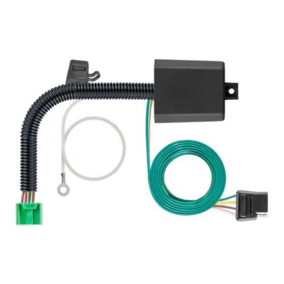
Product Photo
Hardware Photo
NOTICE
Before you begin installation, read all instructions thoroughly.
Proper tools will improve the quality of installation and reduce the time required.
All steps must be followed to ensure the product will function properly. Once installed,
test for proper function by using a test light or connecting a properly wired trailer.
Maintenance
Periodic inspection of all wires and connections should be performed
to ensure there is no visible damage or loose connections.
ECN11308
•
PAGE 1 OF 3
Advertisement

Subscribe to Our Youtube Channel
Related Manuals for curt 56519


Summary of Contents for curt 56519
- Page 1 * Representative vehicle shown Maintenance Periodic inspection of all wires and connections should be performed to ensure there is no visible damage or loose connections. 56519-INS-RA • 11/17/2023 • ECN11308 •...
- Page 2 From inside the cubby area from step 2, attach the white connector housing to the mating housing (the connector is located on the driver-side wheel well body in the upper left side of the cubby). 56519-INS-RA • 11/17/2023 • ECN11308 •...
- Page 3 When not in use roll up and store in a convenient, out of the way location. Secure any loose wires with provided cable ties. Reinstall all items removed during install. If it was disconnected at the beginning of the installation, reconnect the negative battery terminal. Install the provided 4-flat dust cover to help prevent corrosion. 56519-INS-RA • 11/17/2023 •...
Need help?
Do you have a question about the 56519 and is the answer not in the manual?
Questions and answers