
Related Manuals for CenterLine VeriFast MicroView 4.0


Summary of Contents for CenterLine VeriFast MicroView 4.0
- Page 1 ® Connecting Needs with Capabilities VeriFast™ MicroView 4.0 Ethernet / IP User Manual Ver. 2.1 – October 2024 FDP-VFA-MCV4.0-UM-2.1-1024...
-
Page 2: Contact Information
In issuing and making this document available, CenterLine (Windsor) Limited is not undertaking to render professional or other services for or on behalf of any person or entity. Nor is CenterLine (Windsor) Limited undertaking to perform any duty owed by any person or entity to someone else. -
Page 3: Table Of Contents
Table of Contents Contact Information ................................2 Supporting Documentation .............................. 4 Safety Information ................................4 Equipment Lockout Procedure ........................... 4 Potential Hazards Related to the VeriFast™ MicroView 4.0 and Surrounding Equipment ........4 Equipment Overview ................................ 5 Intended Use of Equipment ............................5 Equipment Configuration ............................ -
Page 4: Supporting Documentation
• CenterLine has made every effort to ensure that the descriptions and procedures illustrated in this user manual are accurate. However, CenterLine reserves the right to make product changes that might not be reflected in this document. -
Page 5: Equipment Overview
Equipment Overview Intended Use of Equipment The VeriFast™ MicroView 4.0 (also referred to as “MicroView 4.0”) is a process monitor that allows the simple integration of analog linear position sensing devices into resistance welding systems that require Ethernet/IP communication. A maximum of 2 analog devices can be connected to and monitored by the MicroView 4.0 at a time. -
Page 6: How It Works
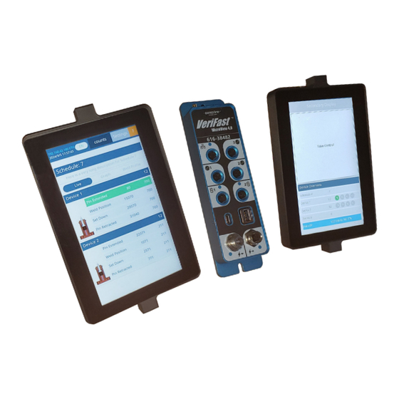
How it Works The Process Monitor (see Figure 1) can monitor up to two of the following analog linear position sensing devices: VeriFast™ IA VeriFast™ LPT VeriFast™ LVDT (requires Generic device that operates on 0 to 10 V ... -
Page 7: Pinout Diagram Of The Process Monitor
Pinout Diagram of the Process Monitor Figure 2 – Pinout Diagram of the VeriFast™ MicroView 4.0 Process Monitor VeriFast™ MicroView 4.0 – User Manual – Ver. 2.1... -
Page 8: Dimensions Of The Process Monitor
Dimensions of the Process Monitor Figure 3 – Dimensions of the Process Monitor Part Ordering Information The VeriFast™ MicroView 4.0 is marked with labels providing information about your specific configuration. When ordering a replacement component, please check your own equipment to find its specific part number. -
Page 9: Installation Guidelines
Installation Guidelines CenterLine recommends that qualified electrical personnel be involved with the setup and operation of the VeriFast™ MicroView 4.0. Also, a qualified weld engineer or quality control personnel should be available for tolerances adjustments and scaling, when required. Mounting the Process Monitor The Process Monitor must be mounted on a flat surface in a convenient location on the machinery or fixture that will be monitored. -
Page 10: Mounting The Clcs Hmi(S)
Ground the Process Monitor by attaching a Grounding Grounding Braid (not provided) to the location indicated in the Braid image on the right. The other end of the Grounding attaches here Braid must be attached to the grounding terminal on the main equipment. -
Page 11: Establishing The Connections For The Microview 4.0
Establishing the Connections for the MicroView 4.0 Establish the connections indicated in Figure 5. Ethernet/IP Communication Connection Process Monitor Monitored Devices Monitored Devices VeriFast™ IA, VeriFast™ IA, Generic Generic LVDT LVDT CLCS HMI (If equipped) CLCS HMI Power Power (IN) (OUT) Installation Precaution for Field Block Applications: Prior to connecting a VeriFast™... -
Page 12: Ethernet/Ip Communication
Ethernet/IP Communication The MicroView 4.0 process monitor is a self-contained fastener detection system, with integrated Ethernet IP communication, which allows the monitoring process to be sent directly to the machine/PLC and not depend on direct output selection. This characteristic expands the capability of the integrating system to monitor and process parameters from the PLC control unit. -
Page 13: Input Assembly Instance Mapping
Table 2 – Inputs for Ethernet/IP Communication of VeriFast™ MicroView 4.0 Inputs_4_100 (size 4 bytes) Input range (dec) DINT Device 1 0 - 32767 DINT Device 2 0 - 32767 DINT Device 3 * 0 - 32767 BYTE Device 1 State_Window 0 - 31 BYTE Device 2 State_Window... -
Page 14: Output Assembly Instance Mapping
• Device 1/2/3 State_Window *: Number that represents the State and the Device specific position status. Device State and Position [1 byte] BYTE �������� �������� Device State Positions Value (1) / (hex) (dec.) b7-b5 0-1F 0-31 Meaning: The Device is enabled and Position 4 is active. For example, for a lower electrode, the pin is retracted. -
Page 15: Changing The Default Passwords
Changing the Default Passwords The VeriFast™ MicroView 4.0 is configured with two default passwords to protect menus at different usage levels (user and maintenance level). Changing both passwords during the initial setup of the VeriFast™ MicroView 4.0 is strongly recommended in order to improve the security and safety of your equipment. -
Page 16: Teaching The Microview 4.0
Teaching the MicroView 4.0 Two Teach screens allow the user to teach the schedules for the devices connected to the MicroView: • Teach Screen – for teaching schedules for regular applications • Step-Thru Teach Screen – for teaching schedules that are typical to robotic applications. Both screens are protected by passwords, see the Changing the Default Passwords section on page 12. -
Page 17: Troubleshooting Quick Guide
11. Ensure that the IP address is correctly set with the PLC and VeriFast™ MicroView No Ethernet/IP 4.0. See the VeriFast MicroView 4.0 – communication Screen Guide document for instructions. Ethernet cable is connected, but is its LED blinking? Ensure that the PLC and VeriFast™... -
Page 18: Decommissioning
Decommissioning Preparing for Storage The following guidelines should be followed when removing a VeriFast™ MicroView 4.0 from service: • Disconnect the VeriFast™ MicroView 4.0 system from all external supplies (i.e., electrical) and connected devices. Identify the connections to facilitate a future installation. •...
Need help?
Do you have a question about the VeriFast MicroView 4.0 and is the answer not in the manual?
Questions and answers