Table of Contents
Troubleshooting

Related Manuals for CenterLine VeriFast MicroView 1.0

Summary of Contents for CenterLine VeriFast MicroView 1.0
- Page 1 c o n n e c t i n g n e e d s w i t h c a p a b i l i t i e s VeriFast MicroView 1.0 User Manual MicroView 5-port Dual Device MicroView 10-port Dual Device MicroView 5-port Single Device Ver.
- Page 2 Product Sales and Support The VeriFast™ MicroView is a component of a resistance welding system manufactured by: For all replacement parts and service inquiries, contact CenterLine’s inside sales department: Telephone: 519.734.8330 Fax: 519.734.2006 Toll Free in Canada & US: 1.800.268.8330 Email: info@cntrline.com...
- Page 3 In no event will CenterLine (Windsor) Limited be responsible or liable to any party for any personal injury, property or other damages of any nature whatsoever, whether special, direct, indirect, incidental, consequential or compensatory, directly or indirectly resulting from the publication, use of, or reliance on this document, and also from the use of the equipment described herein.
- Page 4 This page is intentionally left blank.
-
Page 5: Table Of Contents
Table of Contents Preface ................................. 7 Who Should Use This Manual ........................7 Purpose of This Manual ..........................7 Conventions Used in This Manual ........................ 7 Terminology and Symbols Used Throughout This Manual ................8 Safety Information ............................... 9 Important Safety Information ........................9 Handling the VeriFast™... - Page 6 Re-Calibrating the Signal Conditioner for Most Applications ..............26 Re-Calibrating the Signal Conditioner for Distinct Applications ..............27 Software Overview ............................28 Screens Navigation Chart ........................... 28 Landing Screen / Screen Saver ........................28 Run Screen ..............................29 Password Screen ............................30 User Password ...........................
-
Page 7: Preface
VeriFast™ MicroView controller. For assistance with any other customized products or non-standard applications, additional support is available from CenterLine. Please refer to the inside front cover of this manual for CenterLine contact information. To prevent potentially serious or fatal injury, this manual must be read and understood in its entirety prior to installation, operation, or maintenance of any VeriFast™... -
Page 8: Terminology And Symbols Used Throughout This Manual
Terminology and Symbols Used Throughout This Manual Throughout this manual, all the safety related notes have been identified by the following terms: This symbol relates information about practices or situations that can lead to personal injury or death, property damage, or economic loss. Attention statements help you to: •... -
Page 9: Safety Information
• Equipment is not to be modified, adapted, or changed without consulting the relevant sections of this manual or the manufacturer (please refer to the inside front cover of this manual for CenterLine contact information). • Before any installation, maintenance, or repair work is started, all... -
Page 10: Potential Hazards Related To Verifast™ Microview
Potential Hazards Related to VeriFast™ MicroView The VeriFast™ MicroView system has no specific hazards related to it. However, as the VeriFast™ MicroView is used in conjunction with other equipment such as welding equipment and machinery, robot, air supply, etc., the user should be aware of the warnings, hazards, and precautions related to the use of the equipment as a whole. -
Page 11: Equipment And Process Overview
Equipment and Process Overview Intended Use of Equipment The VeriFast™ MicroView 1.0 is a stand-alone controller that allows simple integration of analog linear position sensing devices into resistance welding systems that require digital I/O. The VeriFast™ MicroView 1.0 is available in three configurations: •... -
Page 12: Verifast™ Microview Configuration
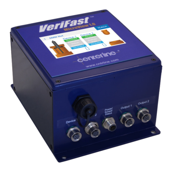
VeriFast™ MicroView Configuration The three existing configurations of the MicroView controller module are illustrated below, each with corresponding connection cables. 5-port Dual Device Controller and Connection Cables HMI Display Output Ports* (Digital) USB Port Power/Schedule/Status Control Port * Devices Ports* (Inputs) * For cable requirements, see Table 2 below. -
Page 13: 10-Port Dual Device Controller And Connection Cables
10-port Dual Device Controller and Connection Cables HMI Display Input Ports* (Digital) USB Port Output Ports* (Digital) Devices Ports* (Inputs) * For cable requirements, see Table 3 below. Figure 2 – Configuration of VeriFast™ MicroView 10-port Dual Device Controller For the cables required to connect the VeriFast™ MicroView 10-port Dual Device Controller, see Table 3 below. -
Page 14: 5-Port Single Device Controller And Connection Cables
5-port Single Device Controller and Connection Cables HMI Display USB Port Device Port* (Input) Output Ports* (Digital) * For cable requirements, see Table 4 below. Figure 3 – Configuration of VeriFast™ MicroView 5-port Single Device Controller For the cables required to connect the VeriFast™ MicroView 5-port Single Device Controller, see Table 4 below. -
Page 15: Description Of I/O
Description of I/O Digital Inputs The VeriFast™ MicroView digital inputs are 30 V tolerant PNP inputs. For a 24 V input, the maximum current drawn will be less than 1 mA. • Schedule Inputs (4 Bits) Binary 1 Binary 2 Binary 4 Binary 8 Table 5 –... -
Page 16: Analog Inputs
P2 – Position 2 – Output is HIGH when the analog signal is within the defined tolerance in reference to taught nominal position. That is: i. “Weld Position” – for VeriFast™ LVDT or Laser ii. “Weld Position” – for LPT P3 –... -
Page 17: Dimensions Of Verifast™ Microview Controller
Dimensions of VeriFast™ MicroView Controller Figure 5 – Dimensions of VeriFast™ MicroView Controller (all configurations) Part Ordering Information The MicroView is marked with labels providing information about your specific configuration. When ordering a replacement component, please check your own equipment to find that specific part number. -
Page 18: Installation Guidelines
(e.g., power, air, water) provided to the devices connected to MicroView are de-energized and locked out. CenterLine recommends that qualified electrical personnel be involved with the setup and operation of the MicroView. Also, a qualified weld engineer or quality control personnel should be available for tolerances adjustments and scaling, when required. -
Page 19: Wiring The Ports Of Verifast™ Microview
Wiring the Ports of VeriFast™ MicroView 5-port Dual Device Port Configuration Port on MicroView / Function Connected Device Device 1, Device 2 Ports (Inputs) Primary Coil 1 Primary Coil 2 Secondary Coil 1 VeriFast™ LVDT Secondary Coil 2 Shield +24 VDC No Connection 0 VDC Analog / Laser... -
Page 20: 10-Port Dual Device Port Configuration
10-port Dual Device Port Configuration Port on MicroView / Function Connected Device Device 1, Device 2 Ports (Inputs) Primary Coil 1 Primary Coil 2 Secondary Coil 1 VeriFast™ LVDT Secondary Coil 2 Shield +24 VDC No Connection 0 VDC Analog / Laser No Connection 0-10 VDC Analog Signal No Connection... - Page 21 Port on MicroView / Function Connected Device CN-3 Not Connected Device 2, Weld Position VeriFast™ LVDT Not Connected Device 2, Pin Extended Not Connected Device 2, P2 Analog / Laser Not Connected Device 2, P1 Not Connected Device 2, Weld Position Balluff LPT Not Connected Device 2, Gun Opened...
-
Page 22: 5-Port Single Device Port Configuration
5-port Single Device Port Configuration Port on MicroView / Function Connected Device Device 1 Port (Inputs) Primary Coil 1 Primary Coil 2 Secondary Coil 1 VeriFast™ LVDT Secondary Coil 2 Shield Output Device Ports and Power / Schedule Port CN-1 +24 VDC VeriFast™... -
Page 23: Setup Scaling
Setup Scaling After the MicroView is mounted and wired, the necessity of performing a setup procedure (called “Scaling”) depends on the type of the measuring unit that will be used during the operation process (i.e., counts, mm, inch): Using Counts during operation – No setup (scaling) of the MicroView is necessary. •... -
Page 24: Changing The Default Passwords
Changing the Default Passwords When you purchase a new VeriFast™ MicroView system, it is configured with two default passwords to protect menus at different usage levels (user and maintenance level). Changing both passwords during the initial setup of the MicroView system is strongly recommended in order to improve the security and safety of your equipment. - Page 25 The System Settings Screen (accessible from More button) screen (illustrated on page 40) displays. This screen provides access to menus that allow the following: • Change User and Maintenance Passwords; • Enable or disable devices; • Access to on board data storage. Press on , respectively, to change each password.
-
Page 26: Re-Calibrating The Signal Conditioner (If Necessary)
Re-Calibrating the Signal Conditioner (If necessary) Re-Calibrating the Signal Conditioner for Most Applications When delivered to the customer, the VeriFast™ LVDT used in connection with the MicroView is fully calibrated for use with a 22 mm weld pin stroke. If a 50 mm weld pin stroke is being used, or if, for any other reason, you suspect that your equipment needs to be recalibrated, follow the instructions below. -
Page 27: Re-Calibrating The Signal Conditioner For Distinct Applications
For certain LVDT weld bodies that have geometric variances, following the calibration steps above can repeatedly lead to a failed calibration. In those rare occasions, a slightly modified calibration procedure should be followed, as illustrated next in the Re-Calibrating the Signal Conditioner for Distinct Applications section. -
Page 28: Software Overview
Software Overview Screens Navigation Chart Figure 9 – VeriFast™ MicroView Screens Navigation Chart Detailed descriptions of each screen follow below. Landing Screen / Screen Saver Once the MicroView is plugged in, the HMI will display the landing screen shown in Figure 10. This screen also serves as a screen saver every time the MicroView is in the Run screen (see page 29) and the HMI goes untouched for ten (10) minutes. -
Page 29: Run Screen
Run Screen The Run screen (see Figure 11 below) is the normal operating screen of the MicroView. It is used for monitoring the processes associated with the devices connected to the MicroView. While on this screen, the MicroView is actively scanning the analog inputs at a rate of 800 Hz. The user can watch the live data for both devices (Device 1 and Device 2) connected to the MicroView. -
Page 30: Password Screen
Password Screen Two different levels of passwords are used on the MicroView to distinguish users and their access to various levels of menus (see Figure 12 below). The initial passwords provided with the unit can be changed from the System Settings screen shown on page 40 (Run - > Teach - > Maint. Settings - >... -
Page 31: Teach Screen
Teach Screen The Teach screen allows the user to teach the schedules and positions for the devices connected to the MicroView. The access to this screen is protected by the User Password (see Password Screen section on page 30 as reference). Schedule Name Maintenance Settings Live Data... -
Page 32: Step Thru Teach Screen
MicroView as Device 1, this field will indicate the real time position of the weld pin on the VeriFast™ LVDT unit. • – Press this button to return to the previous screen, Run Screen (see page 29). Device Specific Position Statuses (P1, P2, P3, P4) – The listed parameters/positions •... - Page 33 To access and teach the parameters/positions for robot applications using the Step Thru Teach Screen, do the following: Before using the Step Thru Teach Screen, access the Teach screen (see Teach Screen section on page 31). Select the device (Device 1 or Device 2). Ensure that the desired (While on the Teach screen) device remains selected.
-
Page 34: Maintenance Settings Screen
Maintenance Settings Screen The Maintenance Settings screen (shown in Figure 15 below) allows for setting basic functioning parameters related to the VeriFast™ MicroView 1.0. The access to this screen is protected by the Maintenance Password (see Password Screen section on page 30 as reference). Language Displayed Units Time... -
Page 35: Tolerance Screen
• – Press this button to access the I/O Test screen. See section I/O Test Screen on page 38 for details for details. • – Press this button to access the USB Storage screen. See section USB Storage Screen on page 39 for details. •... -
Page 36: Scaling Screen
• – Press this button and a keypad will be displayed, allowing for renaming the selected schedule. • Schedule Number – This field identifies the currently selected schedule number. To navigate through the schedules, use the buttons on the left. Ensure that the desired schedule remains selected. - Page 37 Figure 17 – Scaling Screen The following areas can be identified in the Scaling screen above. • – Press this button to select the device that needs to be scaled. Ensure that the desired device remains selected. • Travel Distance – The number in this field, also called Sensor Maximum Displacement, is a pre-defined number, characteristic to each device.
-
Page 38: I/O Test Screen
I/O Test Screen This screen is a test screen to check the hardware connection between the MicroView unit and the input device (PLC Input Card or Remote I/O Block). (Note: The I/O Test screen is accessible from the Maintenance Settings Screen (see page 34)). Figure 18 –... -
Page 39: Usb Storage Screen
USB Storage Screen The MicroView is capable of recording data when the device measures an analog signal that falls within the P2 and P3 nominal positions. This data is recorded internally and then can be downloaded to a USB flash drive. (Note: The USB Storage screen is accessible from the Maintenance Settings Screen (see page 34)). -
Page 40: System Settings Screen (Accessible From More Button)
System Settings Screen (accessible from More button) Figure 20 – System Settings Screen The following areas can be identified in the System Settings screen in Figure 20. • – Press this button to set a new User Password (see User Password section on page 30). - Page 41 • – When OFF (as shown in the image), this button indicates that the device animation is associated from analog input '0' to '32767' (max. position). If pushed, the button will show 'Invert Image On' and the animation direction changes from '32767' (or max.
-
Page 42: Teaching The Microview
Teaching the MicroView Two Teach screens allow the user to teach the schedules for the devices connected to the MicroView: • Teach screen – for teaching schedules for regular applications (see Teach Screen section on page 31). • Step Thru Teach screen – for teaching schedules for robotic applications only (see Step Thru Teach Screen on page 32). -
Page 43: Teaching Positions For Lpt
Teaching Positions for LPT Table 10 – Teaching Positions for LPT Required Position of LVDT Pin and/or Position Taught * How to teach status of equipment Press the (corresponding) P1: Gun Opened Weld gun fully opened button. Correct part in place Press the (corresponding) P2: Weld Position Correctly orientated fastener... -
Page 44: Maintenance / Troubleshooting
Maintenance / Troubleshooting Important Safety Information Please review the Safety Information section starting on page 9. Follow all plant safety procedures and guidelines, as well as all safety instructions given in this manual before performing any troubleshooting procedures. Only certified personnel should perform any troubleshooting tasks on the machinery. - Page 45 Remove the four M3 Phillips pan head screws holding the electronics board to the LCD screen. Remove the electronics board form the LCD screen. Remove the coin battery from the underside of the electronics board. Insert the new C1225 coin battery into the holder. Match the positive sign (+) on the battery with the positive sign on the holder.
-
Page 46: Resetting Passwords And Settings To Factory Defaults
Resetting Passwords and Settings to Factory Defaults If you have changed passwords on your MicroView and forgotten the passwords, or you need to reset the unit to factory defaults, follow the instructions below. Unplug the MicroView unit to turn it OFF. Remove the four M3 flat head Phillips screws from the top of the MicroView enclosure. -
Page 47: Troubleshooting Quick Guide
Troubleshooting Quick Guide Lockout Equipment • Before starting to troubleshoot the MicroView, ensure that the equipment is disconnected from all sources of power and is in the lockout state. • Before turning ON the equipment, make sure all components are assembled properly. -
Page 48: Decommissioning
Decommissioning Preparing for Storage The following guidelines should be followed when removing a MicroView from service: • Disconnect the MicroView system from all external supplies (i.e., electrical) and connected devices. Identify the connections to facilitate a future installation. • The storage location must be clean, dry, and not expose the MicroView system to mechanical or thermal damage. - Page 49 Should you have any questions after reading this User Manual, please feel free to contact your CenterLine representative. Please refer to the inside front cover of this manual for CenterLine contact information). VeriFast MicroView 1.0 – User Manual – Version 1.9...
-
Page 51: Index
Index 5-port Single Device Controller, 14 of Pins, 22 VeriFast™ MicroView, 12 10-port Dual Device Connection Cables Port Configuration, 20 for 5-port Dual Device Controller, 12 Wiring the Ports, 20 for 5-port Single Device Controller, 14 5-port Dual Device Decommissioning, 48 Cables, 12 Digital Input, 15 Controller Configuration, 12... - Page 52 Safety, 9 Pinout Diagram, 22 Ports Wiring the 10-port Dual Device, 20 Wiring the 5-port Dual Device, 19, 22 Label Process Overview, 11 Wiring of MicroView, 16 Landing Screen, 28 Re-Calibrating the Signal Conditioner, 26 Maintenance, 44 the Signal Conditioner for Distinct Password, 30 Applications, 27 Settings Screen, 34...
- Page 53 Setup User Password, 30 Scaling, 23 Change the, 24 Reset, 46 Signal Conditioner Screen, 30 Re-Calibrating, 26 Re-Calibrating for Distinct Applications, 27 Re-Calibrating for Most Applications, 26 Software Overview, 28 VeriFast™ MicroView Screen Navigation Chart, 28 Analog Inputs, 16 Specifications Battery Servicing, 44 Technical Specifications, 11 Configuration, 12...
Need help?
Do you have a question about the VeriFast MicroView 1.0 and is the answer not in the manual?
Questions and answers