Table of Contents
Advertisement
Quick Links
Advertisement
Table of Contents

Related Manuals for Tiffen Steadicam AXIS


Summary of Contents for Tiffen Steadicam AXIS
- Page 1 Steadicam User Guide ™ ® LIT-850000 Rev. A...
-
Page 2: Table Of Contents
Gimbal index calibration Connectors and pin outs Accessories and part numbers FAQ’s and troubleshooting Contact Tiffen TIP: This table of contents is hyperlinked to navigate you through the respective pages. Jump back to this page by clicking on any page number throughout the user guide. Easy. - Page 3 Axis ® ™ Thank you for adding a Steadicam Axis system to your toolkit! In a world with hundreds of camera stabilizers, only Steadicam has over 50 years of experience creating the finest, most innovative stabilizers used around the globe. No other type of stabilizer maintains that important direct connection between operator and camera, allowing unmatched artistry, nuance and feeling with every camera move.
-
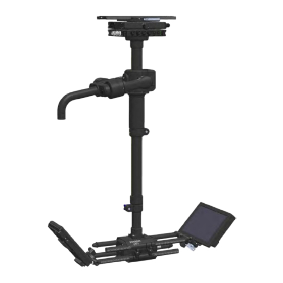
Page 4: Get To Know The Axis Components
Get to know the Axis components Steadicam Axis sled Top stage Dovetail plate and clamp Volt electronics inside Balance knobs Gimbal handle Gimbal Volt motors Gimbal grip Upper post section Monitor Battery mount Post clamp 15mm LWS monitor rods Lower post section... - Page 5 Top Stage components Accessory M12 rod threads Dovetail clamp Volt adjuster dials Volt gimbal connector Volt trim and pause buttons P-tap power port Volt menu, mode and power LEDs Camera tiedown screws Dovetail release button Dovetail clamp lever Dovetail plate Spirit level Side-to-side balance knobs P-tap power port...
-
Page 6: Gimbal Components
Gimbal components Volt tilt/roll motors Pan bearings Gimbal handle Volt pan motor inside Arm post receiver 1/2” Volt gimbal connector Drive belts Gimbal yoke Gimbal grip Gimbal clamp Volt gimbal button I Volt gimbal button II (Mode) & LED I (Preset) &... -
Page 7: Base Components
Monitor power port, mini XLR 15mm rods, 60mm spacing with M12 threaded ends NOTE: All power ports on Steadicam Axis are unregulated battery voltage, typically around 14V. Both HD video lines are direct connections from top stage to base with no processing. -
Page 8: Included Accessories
Slide release button Yoke for Axis sled Balancing pin 1/2” Arm hanger Dock locking knob Stand receiver 5/8” Aircraft locking pin Steadicam Axis gimbal cable Balance weights Highly flexible cable 1/4 Lb (114g) weights (4) 1/2 Lb (228g) weights (2) 30” length included with Axis... -
Page 9: Resources
The Tiffen Steadicam website has a deep well of resources about all available (and many legacy) products. There are also dozens of technical and how-to videos on the Tiffen YouTube page. And don’t forget to grab your copy of The Steadicam Operator’s Handbook! Here is a brief list with links to help you get started: •... -
Page 10: Base Assembly
Base assembly The Axis kit arrives with a few components ready to be assembled before the first use. Gather all the parts, then follow each numbered step on this diagram with corresponding details on the following page. Parts for base assembly: • Battery and monitor rods (4) • (4) 20mm M5 screws •... - Page 11 Base assembly 1. Install two rods for the battery, one with a rod stop facing forward, both machined ends facing the rear. 2. Tighten the battery rod clamps with matching rod numbers aligned within the rounded cutout. 3. Attach the battery pivot to the rods with two included M5 x 20mm screws, using the 4mm Allen wrench. 4.
-
Page 12: Prepare The Axis Sled
Now let’s set up the Axis system! Once your sled is assembled, follow along to get the rig ready for action. You’ll need a sturdy stand, along with the Steadicam Axis kit and your camera system of choice. Place the dock onto the stand... - Page 13 Prepare the Axis sled The post and gimbal are adjustable for length and position. For general operating, we prefer having the gimbal close to the top stage and the post as short as possible to keep the rig out of the way. Extending the post and lowering the gimbal is an easy way to add lens height or go lower in low mode.
-
Page 14: Attach The Camera
Attach the camera We want to attach the dovetail to the camera so that we have the widest possible range of adjustment, both fore-aft and side-to-side. We start this process by finding the camera’s center of gravity (c.g.) or balance point, then properly position the dovetail plate relative to the camera’s c.g. Your camera should be fully built with lens, battery, film, and any accessories you need. Heavy cameras with an external power input may utilize an optional cable to pull power from the 3-pin CAM connector on the Axis and eliminate the camera’s on-board battery. Lightweight cameras usually benefit from additional weight, like on-board batteries. - Page 15 Attach the camera TIP: Some camera setups, such as a DSLR with a large lens, may have the fore-aft balance point outside of the camera body. In this case, find the side-to-side balance first, and then mount the dovetail plate to the camera and use the base of the dovetail plate to find (and mark) the fore-aft balance point.
- Page 16 Volt motors will have maximum effect, so it is worth your time. To balance the Steadicam Axis, you will place the sled onto the balance pin of the dock. Make sure your stand is sturdy enough and has adequate ballast so it can’t tip over. Better yet, have an assistant secure the stand while you balance.
- Page 17 Balance: static The first step to balancing the Axis is to achieve static balance. We want the sled to hang with the post vertical and the sled slightly bottom heavy, keeping the camera at the top and the monitor at the bottom. This doesn’t have to be perfect, but get the rig balance as close as possible given the time you have.
- Page 18 Balance: static Now actively set the post vertical, If the post tilts fore or aft Set the post vertical again. and lighten your grip on the post significantly, slide the battery Use the fore-aft adjuster knob to to observe the rigs behavior. “uphill” on the rods until it’s fine tune the camera position so roughly level, and re-tighten.
- Page 19 Balance: static Last step for static balance is precisely setting the top-to-bottom balance. The measurement we use is called “drop time” which is a count in seconds for the rig to swing from horizontal through vertical (90˚). The slower the drop time, the less bottom heavy the rig is. We want about a 2 second drop time. Hold the post horizontal, let the If it’s quicker than 2 seconds, If it’s slower than 2 seconds, rig go, and count the number of...
-
Page 20: Dynamic Balancing
Balance: dynamic To give those Volt motors maximum effect and reduce unwanted behaviors while panning or tilting the rig, we take balancing one step further; dynamic balance. For each arrangement of camera, monitor position and post length, there is only ONE combination that balances the sled both statically and dynamically. When the battery is within about .25in (6mm) of ideal, the sled will pan flat and feel “sweet.” The physics behind how connected masses rotate and balance is complicated, but the way we achieve dynamic balance with a Steadicam is actually quite simple;... - Page 21 Relax your grip a little while feeling for the balance point, but never let go of the post when the gimbal is unlocked! That’s it. Your Steadicam Axis is now ready for action!
-
Page 22: Volt Operating
Volt system operating The integrated Volt electronics are controlled by the dials, buttons and LEDs on the top stage, plus a pair of buttons and LEDs on the gimbal. If you’re already familiar with Volt systems, the same parts are there. The same adjustments are there. -
Page 23: Volt Modes
Volt modes There are two operating modes: Normal mode simulates a Friction mode holds the sled tilt, Each 2 second press of the traditionally balanced Steadicam, and requires force to change tilt gimbal mode button toggles from returning to a trimmed tilt angle. position, like a tripod fluid head. - Page 24 Volt dials The four dials on the top stage allow you to customize the strength of the Volt motors in all three axes (pan, tilt and roll) independently. Additionally, the Damping dial controls how the system returns the sled to vertical.
-
Page 25: Volt Pan Sub-Menu
Volt pan sub-menu To further customize the performance of the Axis, there are two additional Volt adjustments available in a secondary Menu-2, giving the dials second functions. By toggling from Menu-1 into Menu-2, you are able to adjust pan inertia and pan drag using dial A and dial B. Pan inertia alters the force required to start and stop a pan move, and pan drag is similar to fluid head drag which slows a pan move. -
Page 26: Volt Presets
(0-10) above each. Or keep a set of notes elsewhere. • Remember, button II on the right is the default “preset” button, but goofy operators may swap the two gimbal buttons! See page 34 for details. • For the latest software revisions and operating procedures, visit Tiffen.com. -
Page 28: The Steadicam Vest
Socket height Socket block adjustment Hip pads and buckles Center spar NOTE: Refer to the user guides at Tiffen.com for additional details and for a complete fitting guide. Some customization may be required for optimal fit, depending on your build. -
Page 29: Steadicam Vest
Steadicam vest fitting Adjust the size of the vest using Set the length of the vest to place The shoulder connectors should the Velcro straps at the shoulders, the waist pads low over the hip not ride high and the shoulder back, and hips. -
Page 30: Steadicam Arm
Socket pin Side-to-side adjuster wheels NOTE: Refer to the user guides at Tiffen.com for additional details, instructions for swapping sides, and warnings for the use of A-series arms. Always keep your fingers out of the arm sections when it’s loaded! -
Page 31: Lifting The Steadicam
Lifting the Steadicam Two turns out Turn in Confirm that the side to side Insert the arm pin into the vest Secure the arm to the vest adjustment wheels are set: socket block fully. by tightening both fore-aft adjustment knobs equally, so the The bottom knob should be IMPORTANT: always maintain sockets are parallel. -
Page 32: Arm And Vest Settings
Arm and vest settings With the sled on board, we adjust the lifting strength of the arm. Start with the forearm (nearest the sled) and then adjust the upper arm. The goal is to have each arm section move together as you boom up and down. - Page 33 Arm and vest settings If the rig tends to move straight If the rig tends to move straight away from you; loosen the towards you; loosen the top bottom thumbscrew and slowly thumbscrew slowly, until the rig tighten the top thumbscrew until behaves, and then tighten the the rig is neutral.
-
Page 34: Quick Operating Lessons
Quick operating lessons The two-handed technique was invented by Garrett Brown while working on The Shining, and it has been the preferred method of operating ever since. Basically, the right hand does the work of positioning the sled in space, and the left hand aims the sled (and therefore the camera) by panning and tilting. Try practicing with the Volt strength settings reduced to improve your feel for the rig. - Page 35 Quick operating lessons Your posture is extremely important to getting the most out of your Steadicam Axis. When operating, stand up straight whenever possible, and let the arm and vest do the work. Your standing posture should place most of your weight over one foot, so you’re always ready to move in any direction.
-
Page 36: Swap To Goofy
Swap to goofy Operating with a Steadicam on your left is traditional, as inventor Garret Brown preferred that side. But if you prefer to operate on your right side, we call it goofy foot. Each component, the vest, the arm and the rig are capable of switching to accommodate operating on the right side. -
Page 37: Clamp Adjustment
Clamp adjustment The post clamp, gimbal clamp and dovetail clamp are easy to use and offer a positive lock. You should occasionally test to ensure everything is being clamped fully by trying to move the components with the clamps closed. If anything slides with a camera on board, it will affect your balance, so make sure they’re tight enough. - Page 38 Gimbal alignment procedure Calibration of the gimbal rotational position to the stage and post is critical for proper Volt operation. This alignment is initially factory set and typically will not require adjustment or re-calibration. However, if recalibration is required for any reason, follow the steps listed below. Before proceeding however, follow the troubleshooting suggestions and read through the FAQs starting on page 40 and confirm there isn’t a simpler explanation for the behaviors you’re experiencing.
-
Page 39: Connectors And Pinouts
Connectors and pinouts IMPORTANT: Total Axis current draw not to exceed 10A. All power ports on Steadicam Axis are unregulated battery voltage, typically around 14V. Both HD video lines are direct connections from top stage to base with no processing. -
Page 40: Accessories And Part Numbers
Accessories and part numbers There are some accessories which make each day a little easier and there are others which are absolute necessities. Be careful when using custom or rented power cables, as polarity may not be correct and you risk damaging cameras, monitors or more. -
Page 42: Faqs And Troubleshooting
FAQs and troubleshooting If you’re experiencing undesirable behaviors, first check the following: • Make sure you’re using a fully charged battery. • Cycle the Axis power switch off and then on again. Make sure your Axis is neutrally balanced. • •... - Page 43 FAQs and troubleshooting How much time does the Volt need to transition from high to low mode? • Answer: The normal response time for the Volt to obtain a stable level when transitioning between high and low modes is dependent on the operating temperature and a few other factors. This is normal and should take the Volt an average of 10-20 seconds to stabilize.
- Page 44 FAQs and troubleshooting Balancing FAQ’s Do I really need to dynamically balance the Axis? • Answer: A sled in dynamic balance pans flat without any input from the operator or the Volt. The less work the Volt motors must do, the better the response and the lower the power draw. Faster pans, and whip pans in particular, generate a lot of force. The better the dynamic balance, the less compensating force needs to be applied by the operator or the Volt motors, and the better your operating looks.
- Page 45 I just can’t get it to work! • If all else fails, please reach out to Tiffen Customer service or your nearest Steadicam Dealer. We are here to help.
-
Page 46: Contact Tiffen
There is no implied or expressed warranty regarding this material. STEADICAM®, AXIS™ and VOLT™ are trademarks of the Tiffen Company, LLC. All other trademarks and product names appearing herein are the property of their respective owners. LIT-850000 Rev A © 08/2024 Tiffen Company, LLC. Created by E. Barthelman...
Need help?
Do you have a question about the Steadicam AXIS and is the answer not in the manual?
Questions and answers