Table of Contents
Advertisement
Quick Links
Advertisement
Table of Contents

Related Manuals for Tiffen STEDICAM Shadow Sled


Summary of Contents for Tiffen STEDICAM Shadow Sled
- Page 1 Shadow Sled ™ p/n LIT—257010-A...
- Page 2 Operator’s Handbook” included with your sled. The book can also be purchased separately. The Tiffen Company, 90 Oser Avenue, Hauppauge, NY 11788 • 631-273-2500 • 1-800-645-2522 • www.tiffen.com Tiffen Steadicam Operations, 6933 San Fernando Road, Glendale, CA 91201 • 818-843-4600 • 1-800-593-3331...
- Page 3 The Tiffen Company takes great pride in producing the best inertial stabilizers in the world. stabilizer continues our tradition of excellence and innovation, filling the need for a heavy duty, high ™ performance, and low-cost rig. The Shadow is a system that can evolve with you, with upgrades and accessories to expand its reach.
- Page 4 ™ The base Shadow stabilizer system starts with a sturdy, 2 section, telescoping carbon fiber post coupled to the Ultra stage – with our Overview patented +/– 20º tilt head – and terminates in a new solid base. It comes standard with the Ultra Gimbal, SD LCD Color 700 nit monitor, dual monitor mounts, frameline generator, on-screen artificial horizon, and a...
- Page 5 Structural Dovetail Base solidly mounts gyros, Antlers™, or other accessories. There are two positive clamps for the battery rods and a pull out mounting plate for accessories. The monitor and the battery pack are adjustable in, out, and vertically over a wide range, giving the operators great choices for viewing, balance, and inertial control.
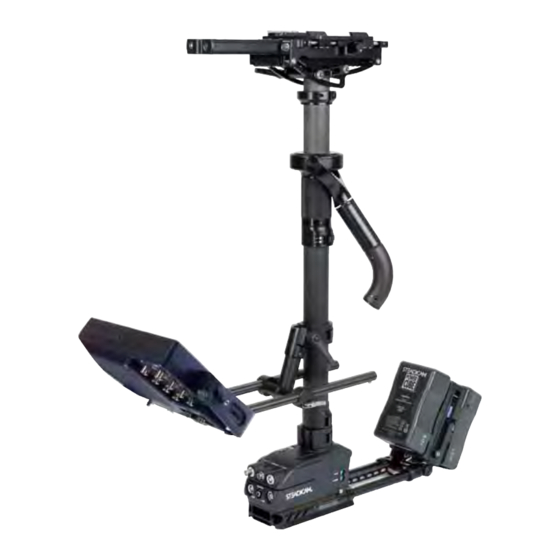
- Page 6 ™ The Shadow Sled Post #1 - connected to the electronics The Shadow Sled ™ Post #2 - connected to tilt head & carries the gimbal Stage electornics Fore-aft adjustment knob Docking ring Monitor Gimbal handle Upper monitor clamp & mount Monitor rods...
- Page 7 Side to side Camera mounting adjustment knob platform Tilt head and Stage clamps electronics Docking ring Gimbal Gimbal clamp PowerCube ™ Batteries Monitor bracket Electronics module Battery rods Integral dovetail base...
-
Page 8: Supplied Accessories
standard package includes the sled, with a non-motorized Ultra ™ 2® The Shadow stage, V-lock battery mount, 7in monitor, and an accessory package, lightweight Ultra 2® vest ™ and the G-70x arm. Accessories Supplied Accessories* part number Camera mounting dovetail 252-7410 Blue Whale gimbal tool 800-7114... - Page 9 Hard case (vest and arm) 011-0330 PowerCube Batteries FFR-000053 IDX VL-4S battery charger FFR-000008 Battery hard case 011-0368 Bag, tool kit FFR-000013 Allen wrench pocket tool MSC-150890 Screwdriver MSC-191115 Saddle bag/sand bag FFR-000014 Steadicam logo cap FFR-000021 ® Spare ratchets with hardware Slanted F-bracket &...
- Page 10 The Tiffen Company, 90 Oser Avenue, Hauppauge, NY 11788 631-273-2500 • 1-800-645-2522 • www.tiffen.com Tiffen Steadicam Operations, 2815 Winona Avenue, Burbank, CA 91504 Phone: 818-843-4600 • 818-843-8321...
- Page 11 800-7400 Stage: Ultra /Shadow 2® ™ p/n LIT-257010-B...
- Page 12 Stage mechanics and The motorized stage is position sensing – much like a focus motor system for a adjustments lens. One use of this feature is to set the stage to the center of travel, both fore-aft 800-7400 Stage The dovetail clamp lever has three and side to side –...
- Page 13 The stage connectors Forward, flanking the stage: The 800-7400 (Ultra 2® stage on these pages is shown with an Ultra . It 2® may look slightly different with another system, such as the Shadow ™ At the rear of the stage, left to right (port side to starboard side): •Camera power connector.
-
Page 14: Smart Motorized Stage
Why the motorized stage is so important for precise operating For precise work, the sled must be carefully balanced or trimmed. Smart Motorized Before operators had the Tiffen’s reliable Stage and precise motorized stage, all balancing and trimming had to be done before the shot and therefore the system’s balance... - Page 15 Removing the remote Charging the remote Changing the frequency Whenever you want to hand the remote off If the transmitter’s battery is low, the To avoid interference with other systems, 1 to your assistant (or charge the remote’s LED will blink continuously after any of 8 channels can be selected via the rotary battery), unscrew the knurled ring.
- Page 16 Ergonomics Orient the remote by screwing the curved handle in or out. If the handle is too far Smart Motorized in, you can’t easily remove the remote via the black knurled ring, and you might Stage have to back the handle off one full turn. Loosening the setscrew a lot further and unscrewing the handle is also how you access the “tilt”...
- Page 17 “Go-to” Buttons and the trim buttons. Then hold one of the go- to buttons down for three seconds. The Smart Motorized Stage green LED will flash twice, and it’s set. You can even program any button on On the remote control, there are three the fly, during the shot, if you have the “go-to”...
-
Page 18: The Tilt Head
The Tilt Head The integral, low profile head is designed Tilt Head to alter the lens angle plus or minus 20 degrees from horizontal with only a minor shift of the camera’s c.g. The most important use of the tilt head is in normal operating. - Page 19 Setting the tilt The operator sets the tilt by releasing the two clamps and manually repositioning the camera to the proper angle. Note: Don’t grab the stage by the nosebox to adjust tilt. Be sure to loosen the arc clamps fully and grab the camera or dovetail plate.
- Page 20 Maintaining Lens Height — Long Modes As the operator tilts the sled, the precious super-high (or super-low) lens height gained with an extended telescoping post quickly disappears. The more one tilts, the more Tilt Head rapidly the lens height is lost. Example 1: Without a tilt head.
-
Page 21: Other Applications
Other Applications One of the more unusual applications of the tilt head is to angle the sled and its components relative to the desired position of the lens. Moving the sled relative to the lens might avoid casting shadows into the shot, seeing one’s own feet, or prevent the sled from hitting something on the set. - Page 22 The Tiffen Company, 90 Oser Avenue, Hauppauge, NY 11788 631-273-2500 • 1-800-645-2522 • www.tiffen.com Tiffen Steadicam Operations, 2815 Winona Avenue, Burbank, CA 91504 Phone: 818-843-4600 • 818-843-8321 © The Tiffen Company, LLC, manual version 7/1/2010...
- Page 23 Posts & Clamps: Ultra /Shadow /Clipper 2® ™ ™ The images, features, and descriptions are taken from several Steadicam ® models and all may not be applicable to the model you have purchased. p/n LIT-257010-C...
- Page 24 Posts and clamps The sections of the telescoping post are adjusted by opening a blue lever, releasing Posts & Clamps the clamp at the bottom of the outer post.. Be sure to support all sled portions that will be freed before you release the clamp. This style of clamp is either completely clamped or free, so don’t force the lever further open than shown.
-
Page 25: Maintenance
Locking the post clamps Accessing the Post 2 to 1 clamp (4-post sleds only) The post clamps are positive locking, Sometimes it’s difficult to get a finger between the tilt head and the clamp snapping shut with a sharp click. lever if the upper post is fully collapsed. - Page 26 Ultra 2™ The shelf is adjusted by removing four screws. Clipper 312/324 ™ Shadow ™ The Tiffen Company, 90 Oser Avenue, Hauppauge, NY 11788 631-273-2500 • 1-800-645-2522 • www.tiffen.com Tiffen Steadicam Operations, 2815 Winona Avenue, Burbank, CA 91504 Phone: 818-843-4600 • 818-843-8321 © The Tiffen Company, LLC, manual version 7/1/2010...
- Page 27 Gimbal: Ultra /Shadow 2® ™ p/n LIT-257010-D...
- Page 28 The gimbal The Ultra gimbal (also used on the The Gimbal & 2® Shadow series stabilizer) uses high- ™ Centering precision and high load bearings, and the body, yoke, and handle are precisely registered to each other. The yoke’s shape and contoured edges extends the range of motion without interference and promotes a better operating grip over a wider range.
- Page 29 Centering the gimbal Tip: We urge you to test your gimbal’s centering • Place the gimbal on the docking stud (as you would for normal balancing), give with a normal drop yourself a 3 to 4 second drop time, and aim the camera along a line through the two time, and then with bearings in the yoke, as shown in the left photo.
- Page 30 The Tiffen Company, 90 Oser Avenue, Hauppauge, NY 11788 631-273-2500 • 1-800-645-2522 • www.tiffen.com Tiffen Steadicam Operations, 2815 Winona Avenue, Burbank, CA 91504 Phone: 818-843-4600 • 818-843-8321 © The Tiffen Company, LLC, manual version 7/1/2010...
- Page 31 Set Up p/n LIT-257010-E...
- Page 32 Attaching the Camera Attach the long dovetail plate to the bottom of the camera, centered as closely The basic idea: We want to position the as possible under the camera’s c.g. camera’s center of gravity about .75in Use two screws to keep the plate from General Set Up (2cm) behind the centerline of the post rotating.
- Page 33 After the dovetail drops into place, close The dovetail locking lever has three For more information the locking lever half way and slide the positions: 60º back is fully open and the camera until the fore-aft c.g. mark is dovetail plate can be inserted or released. on general set up, about .75in (2cm) behind the centerline At the half way or 90 degree position, the...
-
Page 34: Static Balancing
Static Balancing For normal operating The sled should be carefully balanced Mount the gimbal on the balancing stud. to help the operator get the shot. Before Even if your C-stand has plenty of sand balancing, the sled should have the bags, it’s a good idea to have an assistant Static Balancing camera and battery attached, all cables... - Page 35 When the sled is very bottom heavy, it has a quick drop time and it will require bigger movements of a weight (camera or battery) to properly balance the sled. When the sled is nearly neutrally balanced top to bottom, very slight movements of any component will have a large effect on balance.
-
Page 36: Dynamic Balancing
Dynamic Balancing acceptable depends upon the operator and the situation. A sled is in dynamic balance when the center post remains vertical as the sled is Dynamic balance can easily and quickly Dynamic Balancing panned (and this is critical) at any and all be achieved by the trial and error method. - Page 37 worrying about it and give one direction a You will discover that as the monitor is test. Just be sure to make a note of which placed higher towards the camera, the direction you move the battery. closer the battery c.g. gets to the center post, and the more the camera c.g.
- Page 38 Inertial control Positioning masses away from the gimbal will increase inertia, while bringing them Always remember to make the sled’s closer to the gimbal (the point of rotation) balance and inertia work for you, not will reduce inertia. Inertial Control against you.
- Page 39 gimbal relative to the camera mounting and battery 5.5in (14cm), creating only stage or the electronics module. 259 pound inch — almost 10 times less angular resistance in the pan axis. We Experiment to become familiar with all love the square law!! that happens as you move components around.
- Page 40 Lens height and the telescoping post Just how high or low a lens height can you get? Lens Height As a rough estimate, in high mode you should be able to get a lens height of about 7.5 feet (2.3m) with an Ultra stabilizer.
- Page 41 But how high can one get the lens? Establishing the primary Alas, the answer isn’t easy. The exact lens height you can achieve with any sled gimbal height range with the depends on your height, the camera weight, and how much additional weight you shortest post in the arm.
- Page 42 Lens Height — High Mode Lens Height Normal range for high mode with short arm post. Range is different if operator is taller or shorter. The range of the G-70x arm is 29in (74cm). If, while wearing the rig, you stretch up ™...
- Page 43 Lens Height — Low Mode You can also extend the telescoping post and balance the rig with the camera further from the gimbal. How much of an increase in lens height you get depends on how heavy the camera is, and how much weight you are willing to add to the bottom of the sled.
-
Page 44: Low Mode
Configuring the sled for low mode In order to configure the sled Low Mode for low mode operating, you must: •Flip the monitor and the camera upside-down. •Attach the optional slanted F- bracket (P/N 252-7906) to the gimbal. •Rebalance the sled, both statically and dynamically. - Page 45 Remove the monitor mount and flip to low mode Balance the sled Always support the monitor. Loosen the Kipp handle, depress the safety button, and The sled can be balanced the same as in slide the monitor bracket straight up or down. To replace, engage the monitor bracket high mode.
- Page 46 The slanted F-bracket (aka CRB) There are two positions for the F-bracket (P/N 252-7906), one for regular side Low Mode operating and one for goofy-foot. Be sure to angle the F-bracket away from you (about 45 degrees forward) when standing in the Missionary position. Regular operating Goofy foot operating The F-bracket brings...
- Page 47 To make low mode operating The slanted F-bracket has several advantages over the original straight easier and more precise: F-brackets. With the new bracket, the gimbal-to-centerpost angle is changed, increasing the gimbal yoke’s clearance Use the tilt head to keep the post more to the centerpost.
-
Page 48: Long Mode
Unusual lens heights, both high and low, is the principal allure of long mode operating. Tiffen’s tool-free clamps make it easy to extend or compress the integral post system, and also to configure the monitor and battery to best advantage for the shot. - Page 49 The operator dynamically balances a long The uselfulness of any long mode sled sled using the same procedures as with a is greatly enhanced by the addition of shorter sled. The trial and error method an integral tilt head and a motorized is fairly quick.
- Page 50 The Stiffening System Any long post sled, whether single or multi-section, suffers from increased Stiffening System flexing. The longer a post, the more it flexes — unfortunately by the cube law. Doubling the post length makes the rig eight times more flexible! The carbon fiber telescoping post is very stiff, but it will need extra rigidity under certain situations.
- Page 51 The Vectran line is given its final ® tension by extending the telescoping posts slightly, pulling out the monitor rods as shown, and/or by tilting the sled horizontal with the monitor down and retightening the line. The stiffening system is very useful with normal length sleds when the shot has violent moves or high stresses, such...
- Page 52 The Tiffen Company, 90 Oser Avenue, Hauppauge, NY 11788 631-273-2500 • 1-800-645-2522 • www.tiffen.com Tiffen Steadicam Operations, 2815 Winona Avenue, Burbank, CA 91504 Phone: 818-843-4600 • 818-843-8321 © The Tiffen Company, LLC, manual version 7/1/2010...
- Page 53 257010 Electronics p/n LIT-257010-F...
- Page 54 Shadow stabilizer base connectors ™ •Top Left: HDSDI, direct connection to HDSDI connector in stage; no Base Connectors connection to the video distribution amplifier. If your electronics fail, you can use this connector to send a composite video signal to the monitor.
- Page 55 Note: If you are not using the HDSDI and/or the HD component lines, you may use them for other purposes, such as a microphone line down the post or speaker wires up the post.
-
Page 56: Video Matrix
Shadow Video Matrix ™ On top of the base is a multi-position switch that determines what standard Video Matrix Connector definition video signal appears on the * Mon (Front Panel) Camera Video Input monitor and at the three video output Camera Video Input with FLG Overlay connectors. - Page 57 Selector Switch Position Clipper 312/324 (257-0003 PCB) 02-25-08 nel) nput erlay nput nel) nput erlay nput nel) nput erlay nel) nput erlay nput erlay osition. sition. position.
- Page 58 How to set up your frameline generator The four buttons on the frameline generator control the framelines, crosshairs, on-screen horizon position, Frameline Generator and battery indicator position, as well as the frameline style, crosshair style, graphic brightness, graphic elements on or off, and two stored frameline and graphic presets.
- Page 59 The charts tell you how it all works — If no buttons are pressed for several If you change something and want to here’s one example. Suppose you want seconds, the FLG will exit the horizon return to these settings, just push the UP to move the position of the horizon position mode.
-
Page 60: Artificial Horizon
monitor is being used, the center two The Artificial Horizon LED’s on display will flash to confirm that a mode change has occurred. Be sure Adjustments, and displays to re-set the zero offset when going to low mode and back. Artificial Horizon The artificial horizon has three controls –... - Page 61 The range switch interacts with the rate Rate Choices switch. Typically, the smaller the range, the less integration you will need. Ranges or rates significantly larger than the Low Pass filter settings (6-Pole default values are not typically used. IIR filter) Setting Setting a Rate 0 (default)
- Page 62 The Tiffen Company, 90 Oser Avenue, Hauppauge, NY 11788 631-273-2500 • 1-800-645-2522 • www.tiffen.com Tiffen Steadicam Operations, 2815 Winona Avenue, Burbank, CA 91504 Phone: 818-843-4600 • 818-843-8321 © The Tiffen Company, LLC, manual version 7/1/2010...
- Page 63 Batteries: Ultra /Shadow 2® ™ p/n LIT-257010-G...
- Page 64 PowerCube batteries and ™ possible to change a jumper so that both rotating mount batteries provide power to the camera. The PowerCube batteries are 6.0 Ah, Remove four screws that hold the Batteries ™ 14.8V. Please read the literature that forward battery mount.
-
Page 65: Discharge Rate
end, and more slowly as the battery is discharged. When the voltage reaches 13.8 volts, the voltage drops off very quickly to 11 volts (within 8 minutes). The batteries have a self-limiting cut-off of 11 volts. Based on this discharge curve, we suggest you set the battery warning at 13.8 volts if your total load is about 30 watts and 8 minutes is enough warning time. -
Page 66: Charging Your Batteries
Some “12 volt” connectors on the sled may have a regulated (fixed) output of 12 to 14.4 volts, regardless of the voltage of the batteries at any given moment. The Tiffen Company, 90 Oser Avenue, Hauppauge, NY 11788 631-273-2500 • 1-800-645-2522 • www.tiffen.com Tiffen Steadicam Operations, 2815 Winona Avenue, Burbank, CA 91504 Phone: 818-843-4600 • 818-843-8321... - Page 67 Vest: Ultra /Shadow 2® ™ p/n LIT-257010-I...
- Page 68 This vest is standard with the Ultra and Shadow stabilizer systems, optional for all 2® ™ other sleds. This vest also comes in a compact version. Vest Parts Emergency release handle Shoulder connector Shoulder pads Adjustable spar Chest pads Chest straps Adjustable buckles pads...
-
Page 69: Fitting The Vest
Fitting the Vest The vest is the major connection between your body and the sled. It must be adjusted properly and feel good on your body. The vest is not intended to be a straightjacket. You should be able to move and breathe easily. The socket block for the arm should move with you and not shift under load. - Page 70 It’s very important how the shoulder pads contact the shoulders and the shoulder connectors are not too high (a common mistake). The Tiffen Company, 90 Oser Avenue, Hauppauge, NY 11788 631-273-2500 • 1-800-645-2522 • www.tiffen.com Tiffen Steadicam Operations, 2815 Winona Avenue, Burbank, CA 91504 Phone: 818-843-4600 • 818-843-8321 © The Tiffen Company, LLC, manual version 7/1/2010...
- Page 71 G-70x Arm: Ultra /Shadow stabilizers ™ 2® ™ p/n LIT-257010-J...
- Page 72 The G-70x ™ The G-70x arm has a total lifting capacity of 12 to 70 pounds and a 29” boom range. G-70x ™ ™ The arm also incorporates a ride control, a quick post change mechanism, an arm post drag control, and a kickback link. Arm post release lever Arm post Forearm section...
-
Page 73: Side To Side
The two side to side screws work independently of one another. Do not tighten the lower screw, but be sure it is all the way in, and then back it out 1/8th of a turn to prevent binding. In and out Looking down at the top “in-and-out”... - Page 74 Basic adjustments: Ride and Lift Each arm segment has two adjusting If you can, preset Ride close to the G-70x ™ knobs: desired level of iso-elasticity in both arm Ride and Lift sections before picking up the sled and The Ride knob alters iso-elasticity from a adjusting Lift.
- Page 75 Adjustment of Lift: Some adjustment tips: Note that the Lift knob has a range of adjustment of 32 All lift adjustments must be done while When adjusting from a light load to a turns. This means that each wearing the rig, so pick up the sled. heavy load: It helps to have an assistant turn of the Lift knob will add Stand in the classic Missionary position...
- Page 76 The G-70x arm “kick back” connector ™ To accommodate both regular and goofy-foot operators, the two mating parts held by G-70x ™ the “parachute” pin can fit together in two ways. The design intent is to “kick back” “Kick Back” the upper arm segment as shown in the photos.
- Page 77 With a back mounted vest Operators with “back mounted” vests should also orient the connection to send the arm to the inside. When using a back mounted vest, set the position, making the upper arm section If you leave the forearm fully iso, it kickback link inwards as shown in the more likely to go over centers and lock has the “helper torque”...
- Page 78 The Tiffen Company, 90 Oser Avenue, Hauppauge, NY 11788 631-273-2500 • 1-800-645-2522 • www.tiffen.com Tiffen Steadicam Operations, 2815 Winona Avenue, Burbank, CA 91504 Phone: 818-843-4600 • 818-843-8321 © The Tiffen Company, LLC, manual version 7/1/2010...
- Page 79 CineMonitorHDevolution CineMonitorHDevolution Operator Manual Rev. 1.2 Dec 10 2009 Doc ref: p/n LIT-257010-K...
- Page 80 The Tiffen Company, 90 Oser Avenue, Hauppauge, NY 11788 631-273-2500 • 1-800-645-2522 • www.tiffen.com Tiffen Steadicam Operations, 2815 Winona Avenue, Burbank, CA 91504 Phone: 818-843-4600 • 818-843-8321 © The Tiffen Company, LLC, manual version 7/1/2010...
Need help?
Do you have a question about the STEDICAM Shadow Sled and is the answer not in the manual?
Questions and answers