Advertisement
Quick Links
Advertisement

Related Manuals for Tiffen STEDICAM Steadimate-RS


Summary of Contents for Tiffen STEDICAM Steadimate-RS
- Page 1 Steadicam Steadimate-RS ® ™ LIT-901000, RevA...
- Page 2 Introduction The Steadicam Steadimate-RS ® ™ Welcome to the Steadicam family! Steadicam began stabilizing film cameras over 40 years ago, and we continue to innovate solutions for today’s digital cinematographers. Designed exclusively for use with the DJI RS 2, RS 3 and RS 3 Pro motorized gimbals, the Steadimate-RS offers many advantages of traditional Steadicam stabilizer operation, without sacrificing the strengths which make motorized gimbals so popular.
- Page 3 The Tiffen Company 90 Oser Avenue Hauppauge, NY 11788 Visit us at Tiffen.com...
-
Page 4: What's In The Box
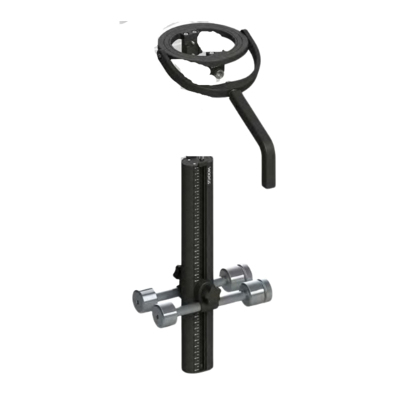
What’s in the box? Steadimate-RS Gimbal Pan bearing Gimbal handle NATO mounts 1/4”-20 threaded accessory hole Thumbscrew locks M4 threads Arm post receiver Balance stand adaptor 5/8” stand to 1/2” stud Lock screws M4 x 10mm Hex wrenches 3mm and 5mm NOTE: if your system is equipped with an A-15 arm, you can fly camera payload up to approximately 7lbs (3.2kg) with the Steadimate-RS. - Page 5 Markers Index tabs 1/4”-20 tripod hole Retaining screw 5mm hex 1/4”-20 retaining screw 15mm weighted rods Rod clamps Screw-on weights (4) .25lbs (.11kg) (4) .50lbs (.22kg) 1/4”-20 threaded holes 1/4”-20 threads Visit tiffen.com for a complete list of available accessories...
- Page 6 Building Steadimate-RS Adding the Steadimate-RS components to your DJI RS 2 or RS 3 stabilizer is a technical task, but if you can balance an electronic gimbal, you can do this! First, we’ll attach the Steadimate-RS gimbal above the handle, then add the post with adjustable weights below the handle, and finally balance the complete system for optimum performance.
- Page 7 Attaching the gimbal Step 2 Ensure the thumb screws are out of the way, so the RSA/NATO ports fully seat into the NATO mounts. Tighten the thumbscrew on each side to secure the Steadimate-RS gimbal to your stabilizer. Don’t over-tighten. NOTE: The four screws on top of the pan bearing that secure the NATO mounts MAY need to be...
- Page 8 Building the base Step 4 Grab the post and attach the two weight rods by threading the rod clamp screws into the captive t-nuts, one on each side. The two rods should always be at the same height on the post. Use the marker numbers to confirm.
-
Page 9: Final Assembly
Final assembly Step 7 Align the Steadimate-RS post with the bottom of the handle, taking care to place the retaining screw at the 1/4”-20 hole near the FRONT of the handle. Confirm the post alignment tabs are on either side of the stabilizer handle. - Page 10 Balancing Steadimate-RS Balancing your Steadimate-RS equipped stabilizer is similar to balancing any mechanical stabilizer. We observe how the system behaves, and make changes. The goal here is to balance the stabilizer only slightly bottom heavy; the handle should hang vertically from the Steadimate-RS gimbal, but tilt up and down with a light touch, and use the least additional weight.
- Page 11 Balancing Use a C-stand or a heavy-duty light stand, with the included adapter, to support the system while balancing. If you don’t have a stand, you can pick it up by the Steadimate-RS handle to test the balance. The post should rest vertically. Feel how much effort it takes to tilt the post up and down by the handle.
- Page 12 Balancing Any time you change the weights, the post tilt may need to be balanced fore-aft. Loosen the rod clamps slightly and slide each weight set fore or aft to, then re-lock the clamps. Slide each rod the same amount, so the weight sets remain parallel.
- Page 13 Balancing Continue removing weight pairs, re-balancing fore-aft, and testing, until the system will not rest with the camera at the top. Then replace one pair of weights so the system is bottom heavy. Re-balance fore-aft, if necessary. Success! This is the minimum balance weight for your camera payload.
- Page 14 Balancing NOTE: You may find it necessary to raise one weight rod slightly higher than the other to maintain a level roll axis. Continue sliding the weights higher on the post until the effort required to tilt the stabilizer is minimized. This is to your preference, depending on your operating style and the shots you’ll be creating.
- Page 15 Notes...
-
Page 16: The Steadicam Vest
The Steadicam vest The Steadicam vest is the major connection between your body and the Steadimate-RS system. It’s adjustable to fit most body types via Velcro straps ® and micro-adjustable buckles. Taking your time to properly fit the vest will ensure you get the highest performance and most comfort out of the system. - Page 17 Putting on a Steadicam vest Adjust the size of the vest using the Velcro® straps at the shoulders, back, and hips. Set the length of the vest to place the waist pads low over the hip bones, yet still allow your legs to lift for climbing stairs.
- Page 18 Putting on a Steadicam vest The fit should be very snug, but not straitjacket tight. You must be able to breathe! Pull down on the vest to make certain the hip pads are centered over your hip bones, and the shoulders fit well. Close the chest buckles first, and finish with the hip buckles.
-
Page 20: The Steadicam Arm
The Steadicam arm The Steadicam arm supports the weight of the Steadimate-RS system, while helping isolate the camera from the operator’s movements, and facilitates booming up and down. The lifting strength of the arm is adjustable to accommodate a wide range in payload, but the adjustment knobs can only be turned with the arm loaded. - Page 21 Attaching the arm Confirm that the side to side Two turns out adjustment wheels are set as follows: The top knob is first turned all the way in, and then TWO turns out. The bottom knob should be turned all the way in. Turn in Insert the arm pin into the vest socket block fully.
- Page 22 Adding the Steadimate-RS Add the Steadimate-RS system to the arm post, and boom up and down a few times. Like balancing, we observe how each section of the arm behaves, and make adjustments. If the arm is lifting too much, or too little, adjust the lift knob on each arm section until both sections of the arm are neutral just above horizontal.
- Page 23 Adding the Steadimate-RS If the rig tends to move straight away from you; loosen the bottom thumbscrew and slowly tighten the top thumbscrew until the rig is neutral. Then re-tighten the bottom thumbscrew. If the rig tends to move straight towards you;...
-
Page 24: Operating Tips
Accessories may be mounted to the 1/4”-20 threads on the handle. This location will not effect balance. • Accessories may also be mounted on the weight rods using aftermarket 15mm x 60mm LWS brackets, in conjunction with balance weights. • Visit tiffen.com for setup videos and more! - Page 26 STEADICAM , Steadimate™, Steadimate- ® RS™, A-15™ and A-30™ are trademarks of the Tiffen Company, LLC. All other trademarks and product names appearing herein are the property of their respective owners. LIT-901000, RevA © 08/2022 Tiffen Company, LLC. by E. Barthelman...
Need help?
Do you have a question about the STEDICAM Steadimate-RS and is the answer not in the manual?
Questions and answers