Bresser WTW 5-in-1, 7002510, 7002511, 7002512 Manual
- Manual (16 pages) ,
- Instruction manual (21 pages)
Advertisement
- 1 ABOUT THIS INSTRUCTION MANUAL
- 2 SCOPE OF DELIVERY
- 3 PARTS OVERVIEW
- 4 LCD DISPLAY
- 5 BEFORE YOU START
- 6 POWER SUPPLY
- 7 INSTALLATION
- 8 RECEIVING MEASUREMENTS AND TIME SIGNAL
- 9 DATA CLEARING
- 10 TIME SETTING
- 11 ALARM CLOCK SETTING
- 12 WEATHER FORECAST
- 13 BAROMETRIC / ATMOSPHERIC PRESSURE
- 14 TEMPERATURE & HUMIDITY
- 15 RAINFALL
- 16 WIND SPEED / DIRECTION
- 17 BEAUFORT SCALE
- 18 WIND CHILL / HEAT INDEX / DEW-POINT
- 19 HISTORY DATA
- 20 MAXIMUM / MINIMUM MEMORY FUNCTION
- 21 HI / LO ALERT
- 22 WIRELESS SIGNAL RECEPTION
- 23 POINTING 5-IN-1 SENSOR TO THE SOUTH
- 24 MOON PHASES
- 25 TROUBLESHOOTING
- 26 SPECIFICATIONS
- 27 CLEANING AND MAINTENANCE
- 28 GENERAL WARNINGS
- 29 Documents / Resources
ABOUT THIS INSTRUCTION MANUAL
![]() These operating instructions are to be considered a component of the device.
These operating instructions are to be considered a component of the device.
Please read the safety instructions and the operating instructions carefully before use.
Keep these instructions for renewed use at a later date. When the device is sold or given to someone else, the instruction manual must be provided to the new owner/user of the product.
This product is intended only for private use. It was developed as an electronic medium for the use of multimedia services.
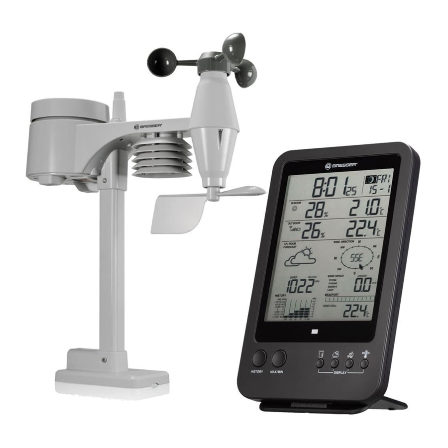
SCOPE OF DELIVERY
Main unit (A), table stand for main unit (B), remote sensor (C), mounting material, instruction manual

Required batteries:
6 pieces of Mignon batteries (1.5V, type AA)
PARTS OVERVIEW
Main unit (Fig. 2)

- SNOOZE / LIGHT button
- HISTORY button
- MAX/MIN button
![]() button
button
 button
![]() button
button![]() button
button
 button
 button
- INDEX-Taste
![]() button
button
 button
![]() button
button![]() button
button
 button
 button
![]() button
button![]() button
button- °C/°F slide switch
 button
 button
- RCC button
- SCAN button
- RESET knob
- Battery compartment
- Alert LED indicator
- LCD display with backlight
- Table stand
Remote sensor (Fig. 3)

- Rain collector (Sinkhole)
- Circular level
- Antenna
- Wind cups
- Mounting pole
- Radiation shield
- Wind vane
- Mounting base
- Mounting claim
- Red LED indicator
- RESET button
- Battery door
- Mounting screws
Remote sensor single parts
Rain gauge (Fig. 4)

- Rain collector (Sinkhole)
- Tipping bucket
- Rain sensor
- Drain holes
Temperature and humidity sensor (Fig. 5)

- Radiation shield/protection
- Sensor casing (Temperature and humidity sensor)
Wind sensor (Fig. 6)

- Wind cups (Anemometer)
- Wind vane
LCD DISPLAY
Time / Calendar / Moon phases (Fig. 7)

- MAX/MIN/PREVIOUS DATA indicator
- Low battery indicator for main unit
- Time
- Ice pre-alert on
- RC Signal strength indicator
- Daylight saving time (DST) icon
- Moon phase
- Day of the week
- Alarm icon
- Date
- Month
Indoor temperature and humidity (Fig. 8)

- Comfort/cold/hot icon
- Indoor indicator
- Indoor humidity
- HI / LO Alert and alarm on
- Indoor temperature
Outdoor temperature and humidity (Fig. 9)

- Outdoor signal strength indicator
- Outdoor indicator
- Outdoor humidity
- HI / LO Alert and alarm on
- Outdoor temperature
- Low battery indicator for sensor
12-hour weather forecast (Fig. 10)

- Weather forecast indicator
- Weather forecast icon
Barometer (Fig. 11)

- Barometer indicator
- Histogram
- ABSOLUTE/RELATIVE pressure indicator
- Barometer measurement unit (hPa / inHg / mmHg)
- Barometer reading
- Hourly records indicator
Rainfall (Fig. 12)

- Rainfall indicator
- Time range record indicator
- Day records indicator
- Histogram
- HI Alert and alarm on
- Current rainfall rate
- Rainfall unit (in / mm)
Wind direction / wind speed (Fig. 13)

- Wind direction indicator
- Wind direction indicator(s) during last hour
- Current wind direction indicator
- Wind speed indicator
- Wind levels and indicator
- Beaufort scale reading
- Current wind direction reading
- Average/Gust wind indicator
- Wind speed unit (mph / m/s / km/h / knot)
- Hi Alert and Alarm
Wind chill/ Heat index/ Indoor dewpoint (Fig. 14)

- Wind chill/ Heat index/ Indoor dewpoint indicator
- Wind chill/ Heat index/ Indoor dewpoint reading
BEFORE YOU START

- Insert batteries for the main unit before doing so for the remote sensor.
- Place the main unit as close as possible to the remote unit.
- Position the remote unit and main unit within the effective transmission range.
When changing batteries always change batteries in the main unit as well as all remote units and replace them in the correct order, so the remote connection can be re-established. If batteries are exchanged in only one of the devices (i.e. the remote sensor) the signal can't be received or can't be received correctly.
Note, that the effective range is vastly affected by building materials and position of the main and remote units. Due to external influences (various RC devices and other sources of interference), the maximum distance can be greatly reduced. In such cases we suggest to position the main unit and the remote sensor at other places. Sometimes all it takes is a relocation of one of these components of a few inches!
POWER SUPPLY
Main unit (Fig. 15)

- Open the battery compartment door.
- Install 3 batteries (AA size 1.5V) strictly according to the polarities shown.
- Reinsert the battery compartment door.
- Once the batteries are inserted, all the segments of the LCD will be shown briefly before entering the radio-controlled time reception mode.
- The RC clock will automatically start scanning for the radio-controlled time signal in 8 seconds.
 NOTE!
NOTE!
- If no display appears on the LCD after inserting the batteries, press the RESET knob by using a pointed object.
- In some cases, you may not receive the signal immediately due to the atmospheric disturbance.
Remote sensor (Fig. 16)

- Open the battery compartment door.
- Install 3 batteries (AA size 1.5V) strictly according to the polarities shown.
- Reinsert the battery compartment door.
NOTE!
- Ensure the water tight O-ring is properly aligned in place to ensure water resistant.
- The red LED will begin flashing every 12 seconds.
Low battery warning
When it is time to replace the batteries, the respective low battery indicator ![]() will be shown near to the time display (batteries for main unit) or near to the outdoor temperature (batteries for remote sensor).
will be shown near to the time display (batteries for main unit) or near to the outdoor temperature (batteries for remote sensor).
INSTALLATION
Remote sensor (Fig. 17-20)
Install the wireless 5-in-1 sensor in an open location with no obstructions above and around the sensor for accurate rain and wind measurement. Install the sensor with the smaller end facing the North to properly orient the wind direction vane.
Add the rubber pads to the rubber pads as shown. Secure the mounting stand and bracket (included) to a post or pole, and allow minimum 1.5m off the ground.
Fig. 17/18: Mounting on pole (Pole Diameter 1" - 1.3" (25 - 33mm)).

Fig. 19: Mounting on the railing.

Fig. 20: Circular level.

Mounting guidelines:
- Install the wireless 5-in-1 sensor at least 1.5m off the ground for better and more accurate wind measurements.
- Choose an open area within 150 meters from the LCD display Main Unit.
- Install the wireless 5-in-1 sensor as level as possible to achieve accurate rain and wind measurements. A circular level device is provided to ensure a level installation.
- Mount the wireless 5-in-1 sensor with the wind meter end pointing to the North to correctly orient direction of the wind vane.
Main station (Fig. 21)
Fig. 21

The unit is designed for desktop or wall mount for easy viewing.
Insert the stand so that the pins on the bottom side reach into the indentions of the station.
The triangular notch on the backside of the main station can be used to mount the device on walls with a wall screw (not included).
RECEIVING MEASUREMENTS AND TIME SIGNAL
Once batteries are placed in the remote unit, it will start transmitting temperature readings at roughly 45 second intervals. As soon as batteries are installed in the main unit it will start searching for a signal from the remote sensor for about 3 minutes. Upon successful reception of the signal, the outdoor temperature will be displayed on the main unit. The main unit will automatically update its readings at about 45 second intervals.
Subsequently, the main unit will attempt to receive the DCF radio signal. The reception symbol ![]() flashes. When the time signal is received after 3-5 minutes, the current time and date appear in the display. The reception symbol will now be shown permanently in the display. Date and time are automatically updated daily at 2:05 o'clock (CET) by the main unit.
flashes. When the time signal is received after 3-5 minutes, the current time and date appear in the display. The reception symbol will now be shown permanently in the display. Date and time are automatically updated daily at 2:05 o'clock (CET) by the main unit.
Manual pairing after battery change
Whenever you changed the batteries of the wireless 5-in-1 sensor, pairing must be done manually.
- Change the batteries to new ones.
- Press and hold the SCAN button for 2 seconds.
- Press the RESET button on the sensor.
NOTE!
- Pressing RESET button at bottom of wireless 5-in-1 sensor will generate a new code for pairing purpose.
- Always dispose old batteries in an environmental safe manner.
DATA CLEARING
During installation of the wireless 5-in-1 sensor, the sensors were likely to be triggered, resulting in erroneous rainfall and wind measurements. After the installation user may clear all the erroneous data from the main unit without a need to reset the clock and re-establish pairing. Simply press and hold the HISTORY button for 10 seconds. This will clear out any data recorded before.
TIME SETTING
The unit automatically set itself accordingly to the Radio Controlled Clock signal it received. To set the clock/calendar manually, first disable the reception by holding the RCC button for 8 seconds.
Manual time setting
- Press and hold
![]() button for 2 seconds until "12 or 24Hr" flashes.
button for 2 seconds until "12 or 24Hr" flashes. - Use
![]() or
or ![]() button to adjust and press
button to adjust and press ![]() button to proceed to the next setting.
button to proceed to the next setting. - Repeat step 2 for setting hours, minutes, seconds, year, month, date, hour offset, language and daylight saving time (DST).
NOTE!
- The unit will automatically exit setting mode if no button was pressed in 60 seconds.
- The hour offset is for DCF and MSF version. Its range is between -23 and +23 hours.
- The language options are English (EN), French (FR), German (DE), Spanish (ES), and Italian (IT).
- DST (Daylight Saving Time) feature is set to Auto (factory set). The clock has been programmed to automatically switch when the daylight saving time is in effect. User can set the DST to OFF to disable the feature.
Disable / Enable RCC signal reception (Fig. 12)

- Press and hold RCC button 8 seconds to disable the reception.
- Press and hold RCC button 8 seconds to enable automatic RCC reception.
ALARM CLOCK SETTING
Turn on/off alarm clock (and ice-alert function) (Fig. 13)
")
- Press
![]() button to show the alarm time.
button to show the alarm time. - Press
![]() button twice to activate the alarm.
button twice to activate the alarm. - Press
![]() button three times to activate alarm with ice-alert function.
button three times to activate alarm with ice-alert function. - To disable the alarm, press
![]() button until the alarm icons disappear.
button until the alarm icons disappear.
NOTE!
- Press SNOOZE/LIGHT button when alarm sounds to interrupt the alarm. The alarm will then start again after 5 minutes.
- Pres
![]() button when alarm sounds to deactivate the alarm until next time.
button when alarm sounds to deactivate the alarm until next time.
Alarm time setting
- Press and hold
![]() button for 2 seconds to enter alarm setting mode. Hours will begin to flash.
button for 2 seconds to enter alarm setting mode. Hours will begin to flash. - Use
![]() or
or ![]() button to adjust the desired value and press
button to adjust the desired value and press ![]() button to proceed to set minutes.
button to proceed to set minutes. - Repeat step 2 to set minutes, then press
![]() button to exit.
button to exit.
NOTE!
Press  button twice when alarm time is being displayed will activate the temperature-adjusted pre-alarm (ice-alert). The alarm will sound 30 minutes earlier if it detects outside temperature is below -3°C.
WEATHER FORECAST
The device contains sensitive pressure sensor built-in with sophisticated and proven software that predicts weather for the next 12 hours.

NOTE!
- The accuracy of a general pressure-based weather forecast is about 70% to 75%.
- The weather forecast is meant for the next 12 hours, it may not necessarily reflect the current situation.
- The "Snowy" weather forecast is not based on the atmospheric pressure, but based on the outdoor temperature. When the outdoor temperature is below -3°C (26°F), the "Snowy" weather indicator will be displayed on the LCD.
- The icon
![]() will flash on the screen when the rainstorm comes.
will flash on the screen when the rainstorm comes.
BAROMETRIC / ATMOSPHERIC PRESSURE
Atmospheric Pressure is the pressure at any location of the Earth caused by the weight of the column of air above it. One atmospheric pressure refers to the average pressure and gradually decreases as altitude increases. Meteorologists use barometers to measure atmospheric pressure. Since variation in atmospheric pressure greatly affected by weather, it is possible to forecast the weather by measuring the changes in pressure.
Select display mode
- Press and hold
![]() button for 2 seconds to enter atmospheric pressure setting mode.
button for 2 seconds to enter atmospheric pressure setting mode. - Use
![]() or
or ![]() button to select between absolute and relative atmospheric pressure:
button to select between absolute and relative atmospheric pressure: - ABSOLUTE the absolute atmospheric pressure of your location
- RELATIVE the relative atmospheric pressure based on the sea level
 button for 2 seconds to enter atmospheric pressure setting mode.
Set relative atmospheric pressure value
- Get the atmospheric pressure data of the sea level (it is also the relative atmospheric pressure data of your home area) through the local weather service, internet and other channels.
- Press and hold
![]() button for 2 seconds until ABSOLUTE or RELATIVE flashes.
button for 2 seconds until ABSOLUTE or RELATIVE flashes. - Press
![]() or
or ![]() button to switch to RELATIVE mode.
button to switch to RELATIVE mode. - Press
![]() button again and the number for RELATIVE flashes.
button again and the number for RELATIVE flashes. - Use
![]() or
or ![]() button to change the value.
button to change the value. - Press
![]() button to save and exit the setting mode.
button to save and exit the setting mode.
NOTE!
- The default relative atmospheric pressure value is 1013 mb/hPa (29.91 inHg), which refers to the average atmospheric pressure.
- When you change the relative atmospheric pressure value, the weather indicators will change along with it.
- The built-in barometer can notice the environmental absolute atmospheric pressure changes. Based on the data collected, it can predict the weather conditions in the forthcoming 12 hours. Therefore, the weather indicators will change according to the detected absolute atmospheric pressure after you operate the clock for 1 hour.
- The relative atmospheric pressure is based on the sea level, but it will change with the absolute atmospheric pressure changes after operating the clock for 1 hour.
Select barometer measurement unit
Press ![]() button several times until the desired measurement unit is displayed: inHg, mmHg or hPa.
button several times until the desired measurement unit is displayed: inHg, mmHg or hPa.
TEMPERATURE & HUMIDITY
Comfort Indication
The comfort indication is a pictorial indication based on indoor air temperature and humidity in an attempt to determine comfort level.

HINWEIS!
- Comfort indication can vary under the same temperature, depending on the humidity.
- There is no comfort Indication when temperature is below 0°C (32°F) or over 60°C (140°F).
RAINFALL
Select display mode
The device displays how many mm / inches of rain are accumulated in a one hour time period, based on current rainfall rate.
Press ![]() button several times until the disered time range is displayed:
button several times until the disered time range is displayed:
- RATE: Current rainfall rate in past an hour
- DAILY: Total rainfall from midnight
- WEEKLY: Total rainfall from the current week
- MONTHLY: Total rainfall from the current calendar month

NOTE!
Rain rate is updated every 6 minutes, at every hour on the hour, and at 6, 12, 18, 24, 30, 36, 42, 48, 54 minute past the hour.
Select rainfall measurement unit
- Press and hold
![]() button for 2 seconds to enter settings mode.
button for 2 seconds to enter settings mode. - Use
![]() or
or ![]() button to select mm (millimeter) or in (inch).
button to select mm (millimeter) or in (inch). - Press
![]() button again to confirm and exit.
button again to confirm and exit.
WIND SPEED / DIRECTION
Reading the wind direction
| Wind direction indicator | Meaning |
 | Real-time wind direction |
 | Wind directions appeared in last 5 minutes (max 6) |

Select display mode
Press ![]() button several times until the desired rate is displayed:
button several times until the desired rate is displayed:
- AVERAGE: average of all wind speed numbers recorded in the previous 30 seconds
- GUST: highest wind speed (gust) recorded from last reading
Fig. 28![]()

The wind level provides a quick reference on the wind condition and is indicated by a series of text icons:
| Wind level | LIGHT | MODERATE | STRONG | STORM |
| Speed | 2-6 mph 3-13 km/h | 9-25 mph 14-41 km/h | 26-54 mph 42-87 km/h | ≥ 55 mph ≥ 88 km/h |
Select wind speed unit
- Press and hold
![]() button for 2 seconds to enter unit setting mode.
button for 2 seconds to enter unit setting mode. - Use
![]() or
or ![]() button to change the unit between mph (miles per hour) / m/s (meter per second) / km/h (kilometer per hour) / knots.
button to change the unit between mph (miles per hour) / m/s (meter per second) / km/h (kilometer per hour) / knots. - Press
![]() button to confirm and exit.
button to confirm and exit.
 button for 2 seconds to enter unit setting mode.
BEAUFORT SCALE
The Beaufort scale is an international scale of wind velocities from 0 (calm) to 12 (Hurricane force).
| Beaufort-Nummer | Beschreibung | Geschwindigkeit |
| 0 | calm | < 1 km/h | < 1 mph < 1 knot | < 0.3 m/s |
| 1 | light air | 1.1-5.5 km/h | 1-3 mph 1-3 knot | 0.3-1.5 m/s |
| 2 | light breeze | 5.6-11 km/h | 4-7 mph 4-6 knot | 1.6-3.4 m/s |
| 3 | gentle breeze | 12-19 km/h | 8-12 mph 7-10 knot | 3.5-5.4 m/s |
| 4 | moderate breeze | 20-28 km/h | 13-17 mph 11-16 knot | 5.5-7.9 m/s |
| 5 | fresh breeze | 29-38 km/h | 18-24 mph 17-21 knot | 8.0-10.7 m/s |
| 6 | strong breeze | 39-49 km/h | 25-30 mph 22-27 knot | 10.8-13.8 m/s |
| 7 | high wind | 50-61 km/h | 31-38 mph 28-33 knot | 13.9-17.1 m/s |
| 8 | gale | 62-74 km/h | 39-46 mph 34-40 knot | 17.2-20.7 m/s |
| 9 | strong gale | 75-88 km/h | 47-54 mph 41-47 knot | 20.8-24.4 m/s |
| 10 | Storm | 89-102 km/h | 55-63 mph 48-55 knot | 24.5-28.4 m/s |
| 11 | violent storm | 103-117 km/h | 64-73 mph 56-63 knot | 28.5-32.6 m/s |
| 12 | Hurricane force | ≥ 118 km/h | ≥ 74 mph ≥ 64 knot | ≥ 32.7 m/s |
WIND CHILL / HEAT INDEX / DEW-POINT
Reading wind chill
Press INDEX button several times until WIND CHILL is displayed.
Reading heat index
Press INDEX button several times until HEAT INDEX is displayed.
| Heat index | Warning | Meaning |
| 27°C - 32°C (80°F - 90°F) | Caution | Possibility of heat exhaustion |
| 33°C - 40°C (91°F - 105°F) | Extreme caution | Possibility of dehydration |
| 41°C - 54°C (106°F - 129°F) | Danger | Heat exhaustion likely |
| ≥ 55°C (≥ 130°F) | Extreme danger | Strong risk of dehydration / sun stroke |
Reading dewpoint (indoor)
Press INDEX button several times until INDOOR DEWPOINT is displayed.
NOTE!
The dew point is the temperature below which the water vapor in air at constant barometric pressure condenses into liquid water at the same rate at which it evaporates. The condensed water is called dew when it forms on a solid surface.
The dewpoint temperature is calculated from the indoor temperature and humidity measured at the main unit.
HISTORY DATA
(all records in the past 24 hours)
The main unit automatically records and displays data of the past 24 hours on the hour.
To check all the history data in the past 24 hours, press the HISTORY button.
E.g. current time 7:25 a.m., Mach 28:
Press HISTORY button repeatedly to view past readings at 7:00am,
6:00am, 5:00am, ..., 5:00am (Mar 27), 6:00am (Mar 27), 7:00am (Mar 27)
The LCD will display the past indoor and outdoor temperature & humidity, value of air pressure, wind chill, wind speed, rainfall and their time and date.
MAXIMUM / MINIMUM MEMORY FUNCTION
- Press MAX/MIN button to check the maximum/minimum records. The checking orders will be: Outdoor max temperature > Outdoor min temperature > Outdoor max humidity > Outdoor min humidity > Indoor max temperature > Indoor min temperature > Indoor max humidity > Indoor min humidity > Outdoor max wind chill > Outdoor min wind chill > Outdoor max heat index > Outdoor min heat index > Indoor max dewpoint > Indoor min dewpoint > Max pressure > Min pressure > Max average > Max gust > Max rainfall.
- Press and hold MAX/MIN button for 2 seconds to reset the maximum and minimum records.
NOTE!
When maximum or minimum reading is displayed, the corresponding timestamp will be shown.
HI / LO ALERT
HI/LO alert are used to alert you of certain weather conditions. Once activated, the alarm will turn on and amber LED starts flashing when a certain criterion is met. The following are areas and type of alert provided:
| Bereich | Verfügbarer AlarmTyp |
| Indoor temperature | HI AL / LO AL |
| Indoor humidity | HI AL / LO AL |
| Outdoor temperaturw | HI AL / LO AL |
| Outdoor humidity | HI AL / LO AL |
| Rainfall | HI AL* |
| Wind speed | HI AL |
*Daily rainfall since midnight
HI / LO alert setting (Fig. 29)

- Press
![]() button several times until the desired area is selected.
button several times until the desired area is selected. - Use
![]() or
or ![]() buttons to adjust the setting.
buttons to adjust the setting. - Press
![]() button to confirm and continue to next setting.
button to confirm and continue to next setting.
 button several times until the desired area is selected.
Enable/Disable HI / LO alert (Fig. 30)

- Press
![]() button several times until the desired area is selected..
button several times until the desired area is selected.. - Press
![]() button to turn the alert on or off.
button to turn the alert on or off. - Press
![]() button again to confirm and continue to next setting.
button again to confirm and continue to next setting.
NOTE!
- The unit will automatically exit setting mode in 5 seconds if no button is pressed.
- When ALERT alarm is on, the area and type of alarm that triggered the alarm will be flashing and the alarm will sound for 2 minutes.
- Press SNOOZE/LIGHT button when alarm sounds to interrupt the alarm. The alarm will then start again after 5 minutes.
- Press
![]() button when alarm sounds to deactivate the alarm until next time.
button when alarm sounds to deactivate the alarm until next time.
The alarm automatically turns off after 2 minutes.
WIRELESS SIGNAL RECEPTION

The 5-in-1 sensor is capable of transmitting data wirelessly over an approximate operating of 150m range (line of sight). Occasionally, due to intermittent physical obstructions or other environmental interference, the signal may be weaken or lost. In the case that the sensor signal is lost completely, you will need to relocate the main unit or the wireless 5-in-1 sensor.
POINTING 5-IN-1 SENSOR TO THE SOUTH
The outdoor 5-in-1 sensor is calibrated to be pointing to North by default. However, in some cases, users may wish to install the product with the arrow pointing towards the South, especially for people living in the Southern hemisphere (e.g. Australia, New Zealand).
- First install the outdoor 5-in-1 sensor with its arrow pointing to the South. (Please refer to 'Installation' chapter for mounting details)
- Press and hold
![]() button for 8 seconds until the upper part (Northern hemisphere) of the compass rose is blinking.
button for 8 seconds until the upper part (Northern hemisphere) of the compass rose is blinking. - Use
![]() or
or ![]() button to change to lower part (Southern hemisphere).
button to change to lower part (Southern hemisphere).


- Press
![]() button again to confirm and exit.
button again to confirm and exit.
NOTE!
Changing from hemisphere setting will automatically switch the direction of the moon phase on the display.
MOON PHASES
In the Northern hemisphere, the moon waxes (the part of the moon we see that glows after the New Moon) from the right. Hence the sun-lit area of the moon moves from right to left in the Northern hemisphere, while in the Southern hemisphere, it moves from left to right. Below are the 2 tables which illustrate how the moon will appear on the main unit.
Northern hemisphere:

Southern hemisphere:

TROUBLESHOOTING
| Problem/Symptom | Solution |
Strange or no measurement of rain sensor |
|
Strange or no measurement of Thermo/Hygro Sensor |
|
 and --- (no signal for 15 minutes) and --- (no signal for 15 minutes) |
|
 and ER (no Signal for 1 hour) and ER (no Signal for 1 hour) |
SPECIFICATIONS
| Main unit | |
| Batteries | 3 x AA, 1.5 V |
| Barometer unit | hPa, inHg, mmHg |
| Barometer measuring range | 540 - 1100 hPa |
| Temperature unit | °C / °F |
| Temperature measuring range | -10° - 50°C |
| Humidity measuring range | 20% - 90% |
| Time display | HH:MM:SS |
| Time format | 12 or 24 hours |
| Calendar display | TT/MM/JR or MM/TT/JR |
| 5-in-1 sensor | |
| Batteries | 3 x AA, 1.5 V |
| Temperature unit | °C / °F |
| Temperature measuring range | -40° - 60°C |
| Humidity measuring range | 1% - 99% |
| Rainfall unit | mm, inch |
| Rainfall measuring range | 0 - 9999 mm (0 - 393.7 inch) |
| Wind speed unit | mph, m/s, km/h, knot |
| Wind speed measuring range | 0 - 112 mph, 0 - 50 m/s, 0 - 180 km/h, 0 - 97 knots |
| Wind direction display | 16 |
CLEANING AND MAINTENANCE
Before cleaning the device, disconnect it from the power supply (remove batteries)! Only use a dry cloth to clean the exterior of the device. To avoid damaging the electronics, do not use any cleaning fluid.
Cleaning the rain collector (sinkhole)

- Rotate the rain collector by 30° anticlockwise.
- Gently remove the rain collector.
- Clean and remove any debris or insects.
- Install all the parts when they are fully clean and dried.
Cleaning the thermo/hygro sensor

- Unscrew the 2 screws at the bottom of the radiation shield.
- Gently pull out the shield.
- Remove carefully any dirt or insects inside the sensor casing
![warning]() NOTE!
NOTE!
The radiation shield comprises different parts inserted one inside another. Two bottom parts are closed. Do not change their order! Do not let the sensors inside get wet!
- Clean the shield with water and remove any dirt or insects.
- Install all the parts back when they are fully clean and dried.
GENERAL WARNINGS
RISK OF CHOKING!
Keep packaging material, like plastic bags and rubber bands, out of the reach of children, as these materials pose a choking hazard.
 RISK OF ELECTRIC SHOCK!
This device contains electronic components that operate via a power source (batteries). Children should only use the device under adult supervision. Only use the device as described in the manual; otherwise, you run the risk of an electric shock.
RISK OF CHEMICAL BURN!!
Leaking battery acid can lead to chemical burns. Avoid contact of battery acid with skin, eyes and mucous membranes. In the event of contact, rinse the affected region immediately with a plenty of water and seek medical attention.
RISK OF FIRE/EXPLOSION!
Use only the recommended batteries. Do not short-circuit the device or batteries, or throw them into a fire. Excessive heat or improper handling could trigger a short-circuit, a fire or an explosion.
NOTE!
Do not disassemble the device. In the event of a defect, please contact your dealer. The dealer will contact the Service Centre and can send the device in to be repaired, if necessary.
Do not immerse the unit in water.
Protect the device from severe shocks!
Use only the recommended batteries. Always replace weak or empty batteries with a new, complete set of batteries at full capacity. Do not use batteries from different brands or with different capacities. Remove the batteries from the unit if it has not been used for a long time.
The manufacturer is not liable for damage related to improperly installed batteries!
Documents / ResourcesDownload manual
Here you can download full pdf version of manual, it may contain additional safety instructions, warranty information, FCC rules, etc.
Download Bresser WTW 5-in-1, 7002510, 7002511, 7002512 Manual
Advertisement


Need help?
Do you have a question about the WTW 5-in-1 and is the answer not in the manual?
Questions and answers