EINHELL GE-WS 18/150 Li, GE-WS 18/150 Li-Solo (34.252.30) Manual
- Operating instructions manual (205 pages) ,
- Operating instructions manual (55 pages) ,
- Original operating instructions (119 pages)
Advertisement
- 1 Symbols
- 2 Layout and items supplied
- 3 Intended use
- 4 Technical data
- 5 Before starting the equipment
- 6 Operation
- 7 Cleaning, maintenance and ordering spare parts
- 8 Storage and transport
- 9 Troubleshooting guide
- 10 Charger indicator
- 11 Service information
- 12 Safety regulations
- 13 Documents / Resources
Symbols

Hazard! - Read the operating instructions to reduce the risk of injury

Keep bystanders and animals away while you are spraying.

Wear a breathing mask, safety goggles, protective gloves and protective clothing suitable for the spray solution being used.

Do not leave the equipment in the sunshine.

Protect the equipment from freezing temperatures.

Do not use in the rain. Protect from the damp!
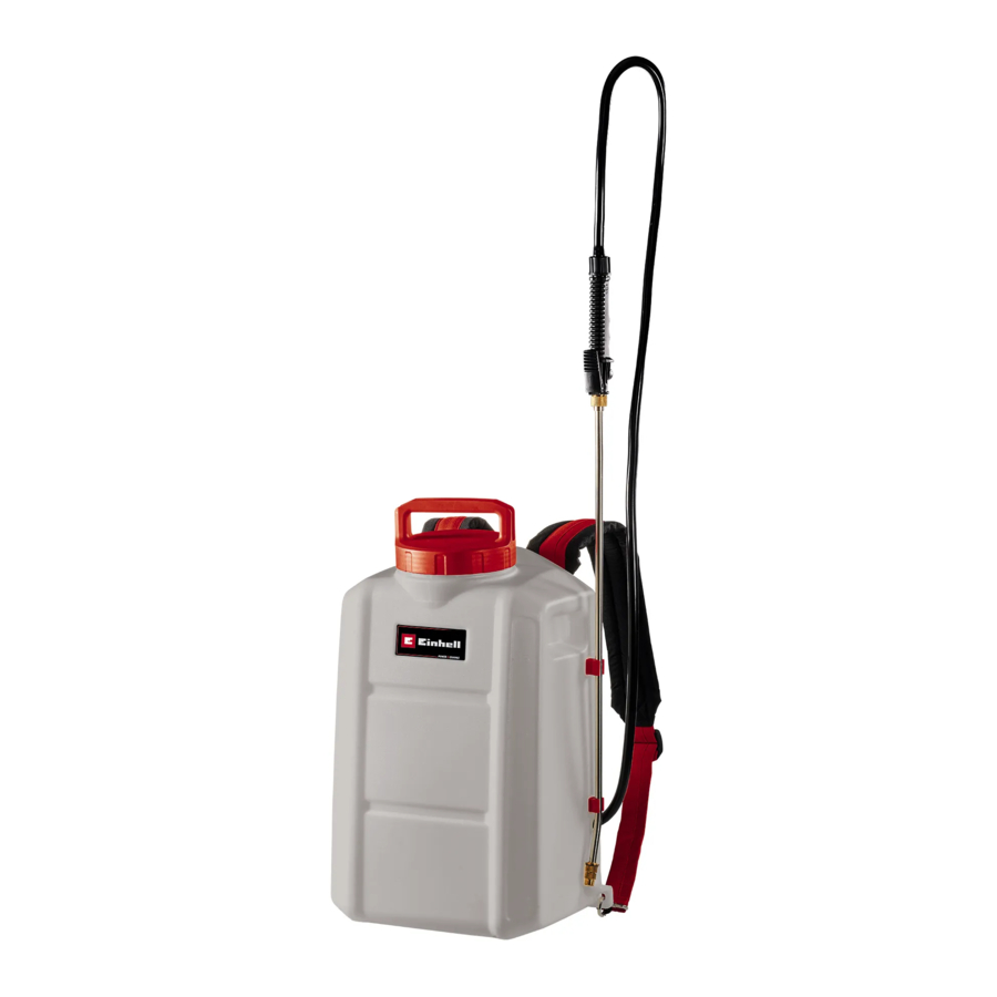
Layout and items supplied
Layout


- Adjustable spray head
- Spray tube
- Release lever
- Spray gun handle
- Hose
- Tank lid
- Tank
- Rechargeable battery cover fl ap
- On/Off switch
- Harness
Items supplied
Please check that the article is complete as specified in the scope of delivery. If parts are missing, please contact our service center or the sales outlet where you made your purchase at the latest within 5 working days after purchasing the product and upon presentation of a valid bill of purchase. Also, refer to the warranty table in the service information at the end of the operating instructions.
- Open the packaging and take out the equipment with care.
- Remove the packaging material and any packaging and/or transportation braces (if available).
- Check to see if all items are supplied.
- Inspect the equipment and accessories for transport damage.
- If possible, please keep the packaging until the end of the guarantee period.

The equipment and packaging material are not toys. Do not let children play with plastic bags, foils or small parts. There is a danger of swallowing or suffocating!
- Pressure sprayer
- Spray tube
- Original operating instructions
- Safety information
Intended use
This pressure sprayer is designed exclusively for spraying the following solutions outdoors and in well ventilated greenhouses.
- Water
- Pesticides
- Weedkillers
- Natural oils dissolved in water (e.g..neem oil, rapeseed oil)
- Fertilizers dissolved in water
The solution to be sprayed must be approved by its manufacturer for distribution using a spraying unit. Arrange to be shown how to use the unit safely if you are not familiar with it.
Liquids to be sprayed, particularly natural oils dissolved in water, must have a water-like consistency. Liquids of greater viscosity cannot be sprayed, or only with lesser power.
Only liquid fertilizers, weedkillers and pesticides that are approved by the local licensing authority in the country of use may be sprayed. At the time of manufacture, no harmful effects on the materials used are known to be caused by these approved substances or natural oils dissolved in water. The fertilizers, pesticides and weedkillers are only allowed to be sprayed in the concentrations specified by the manufacturer of the spray solutions. If in doubt, please contact the relevant manufacturer.
The pressure sprayer is not designed to be used with foodstuff s or to spray liquids that exceed the maximum permitted operating temperature of 40°C. Similarly, it is prohibited to spray acidic, caustic and flammable liquids whose flash point is below 55°C, as well as impregnating agents, disinfectant, paints, varnishes, grease, glazes and synthetically manufactured oils.

Atomized flammable liquids with a flash point in excess of 55°C are also highly combustible.
Never use the pressure sprayer
- as a flame gun
- for storing liquids
- for substances with unknown risk.
The equipment is to be used only for its prescribed purpose. Any other use is deemed to be a case of misuse. The user/operator and not the manufacturer will be liable for any damage or injuries of any kind caused as a result of this.
Please note that our equipment has not been designed for use in commercial, trade or industrial applications. Our warranty will be voided if the machine is used in commercial, trade or industrial businesses or for equivalent purposes.
Technical data
| Power supply: | 18 V DC | |
| Pump type: | Membrane pump | |
| Tank capacity approx.: | 17 l | |
| Filling capacity max.: | 15 l | |
| Delivery rate: | 54-102 l/h | |
| Spray pressure: | 4.5 bar (65 psi) | |
| Nozzle Ø: | 1.7 mm | |
| Optimal spraying distance: | 0.5 m | |
| Technical residual quantity: | 100 ml | |
| Permissible maximum operating temperature: | + 40°C | |
| Spray tube length with connector/nozzle: | 60 cm | |
| Weight when empty: | 4.7 kg | |
| Weight when full: | 19.7 kg | |
The equipment is supplied without batteries and without a charger and is allowed to be used only with the lithium-ion batteries of the Power-XChange series!
The lithium-ion batteries of the Power-X-Change series are allowed to be charged only with the Power-X-Charger.
Sound and vibration
Sound and vibration values were measured in accordance with Annex I, EN 62841-1.
| LpA sound pressure level | 60.3 dB(A) | |
| KpA uncertainty | 3 dB | |
| LWA sound power level | 71.3 dB(A) | |
| KWA uncertainty | 3 dB | |
Total vibration values (vector sum of three directions) determined in accordance with Annex I, EN 62841-1.
Handle
Vibration emission value ah = 2.12 m/s2 K uncertainty = 1.5 m/s2
The stated vibration emission levels and stated noise emission values were measured in accordance with a set of standardized criteria and can be used to compare one power tool with another.
The stated vibration emission levels and stated noise emission values can also be used to make an initial assessment of exposure.

The vibration and noise emission levels may vary from the level specified during actual use, depending on the way in which the power tool is used, especially the type of workpiece it is used for.
Keep the noise emissions and vibrations to a minimum.
- Only use appliances which are in perfect working order.
- Service and clean the appliance regularly.
- Adapt your working style to suit the appliance.
- Do not overload the appliance.
- Have the appliance serviced whenever necessary.
- Switch the appliance off when it is not in use.
- Wear protective gloves.

Residual risks
Even if you use this electric power tool in accordance with instructions, certain residual risks cannot be rules out. The following hazards may arise in connection with the equipment's construction and layout:
- Lung damage if no suitable protective mask is used.
- Contact with hazardous substances. Spray materials can be harmful if inhaled or swallowed or if allowed to come into contact with the skin or eyes. Follow the instructions and wear suitable protective equipment.

This electric power tool generates an electromagnetic field during operation. Under certain circumstances this field may actively or passively impede medical implants.
To reduce the risk of serious or fatal injuries, we recommend persons with medical implants to consult their doctor and the manufacturer of the medical implant prior to using the equipment.
Before starting the equipment
Switch the equipment off and remove the battery before carrying out any assembly work.
Assembling the spray tube and hose
Screw the spray tube onto the spray gun handle

Always check the hose connections. Any leaks must be remedied immediately and the equipment must not be used until this has been done.
Fitting the harness
Attach the fastening hooks for the harness (Item 10c) to the container on the left and right sides (see also Fig. 9).

Preparing spray solution and filling the container
Switch off the equipment and remove the battery.
Note:
- Always follow the manufacturer's instructions when mixing spray solutions. Fill the tank only with the amount of solution you intend to use.
- Observe the quantities to be used as listed by the manufacturer of the solution.
- Spray solution must have a water-like consistency.
- The spray container can be filled with a maximum 15 liters of liquid.
- Pesticides must only be prepared outdoors and never in living quarters, stables, or storage rooms for food and animal feed.
- Spray solutions can be prepared in a separate container and mixed thoroughly before being filled into the container of the pressure sprayer.
- If you intend to use organic spray solutions, they must be filtered prior to filling the sprayer.
- The solution must always be filled in through the filling sieve situated in the tank (Fig. 4/Item 7a).

- Clean the equipment immediately after each use. This is the only way to keep the liquid carrying parts clean and prevent clogging. Clogged components can lead to defects.

- Place the pressure sprayer on a level surface. Unscrew the tank lid (Fig. 5/Item 6) from the tank. On the inside of the tank lid you will see measuring ranges with 5ml, 10ml and 25ml contents.

- Pour the amount of liquid (e.g. water) specified by the solution manufacturer into the spray container. If the spray solution has not been prepared ready for spraying, add the measured quantity of concentrated additive and close the container carefully.
- If you have not already done so, mix the concentrated additive with the water (or other liquid) by shaking the pressure sprayer.
- Apply the name of the spray solution you are using to the spray solution tank (e.g. by means of a sticker)

Installing the battery
Note:
- The equipment is supplied without batteries and without a charger.
- The cover flap closes by itself and is held in position by magnets.
Open and hold the cover flap (Fig. 6/Item 8). Push the battery into the battery mount provided. Make sure that the pushlock button (Fig. 6/Item C) engages as soon as the battery has been pushed in all the way. To remove the battery, proceed in the reverse order.

Charging the battery
- Take the battery pack out of the equipment. To do so, press the pushlock button. (Fig. 6/Item C).
- Check that your mains voltage is the same as that marked on the rating plate of the battery charger. Insert the power plug of the charger into the socket outlet. The green LED will then begin to fl ash.
- Insert the battery pack into the charger.

- In the section entitled „Charger indicator" you will find a table with an explanation of the LED indicator on the charger.

The battery pack can become a little warm during the charging. This is normal.
If the battery pack fails to charge, check:
- whether there is voltage at the socket outlet
- whether there is good contact at the charging contacts
If the battery pack still fails to charge, send
- the charger
- and the battery pack
to our customer service center.
To ensure that items are properly packaged and delivered when you send them to us, please contact our customer service or the point of sale at which the equipment was purchased.
When shipping or disposing of batteries and cordless tools, always ensure that they are packed individually in plastic bags to prevent short circuits and fires.
To ensure that the battery pack provides long service, you should take care to recharge it promptly. You must recharge the battery pack when you notice that the performance of the device drops. Never allow the battery pack to become fully discharged. This will cause it to develop a defect.
Battery charge level indicator
Press the button for the battery charge level indicator (Item A). The battery charge level indicator (Item B) shows the charge status of the battery using 3 LEDs.

All 3 LEDs are lit:
The battery is fully charged.
2 or 1 LED(s) are lit:
The battery has an adequate remaining charge.
1 LED flashes:
The battery is empty, recharge the battery.
All LEDs blink:
The battery temperature is too low. Remove the battery from the equipment, keep it at room temperature for one day. If the fault reoccurs, this means that the rechargeable battery has undergone exhaustive discharge and is defective. Remove the battery from the equipment. Never use or charge a defective battery.
Using the harness
Slip the harness over your shoulders and adjust the length of the harness so that you can work without fatigue. To do so, pull on the two ends of the harness to shorten it (Fig. 9/Item 10a) or on the two harness release mechanisms to extend it (Fig. 9/Item 10b).

Note: Should the fastening hooks for the harness (Fig. 9/Item 10c) come off, attach them back in position again as shown in Figs. 3a-3b.
Operation
Check the equipment for damage before you use it. Never use the equipment if it is damaged.
- Check the tank for damage each time before and after using the equipment.
- Check the hose and all screw connections for damage and leaks each time before and after using the equipment.
Switching on
After inserting the battery, switch the equipment on by turning the On/Off switch to the "I" position (Fig. 10/Item 9).

Switching off
Switch the equipment off by turning the On/Off switch to the "0" position (Fig. 10/Item 9).
Spraying
Note the attached leaflet with the safety instructions.
- Do not use a very wide jet when spraying plants or other objects directly.
- When the trigger lever on the spray gun handle is pressed, recoil forces can occur suddenly, in the worst case scenario causing the spray tube to point towards the body. Always keep tight hold of the spray gun handle.
- Perform spraying only when the tank is vertical or upright.
Switching spraying on/off
- To spray, press the trigger lever on the spray gun handle.

- The spray jet will stop when you let go of the trigger lever.
- If the trigger lever is pressed and then pushed forward (Fig. 12), this locks the lever. The equipment continues spraying until the trigger lever is pulled back again and released.


Notes!
- If the integrated pump contains too little spray solution or none at all, it will run after the pressure sprayer is switched on. Press the trigger lever on the spray gun handle for several seconds. The pump will fill up and spray solution will be ejected irregularly. Once the spray solution is ejected evenly, the pump will switch off upon releasing the trigger lever and will switch on again upon pressing the lever.
- If there is too little spray solution in the spray solution container, the pump will suck in too little spray solution (see "Safety regulations") and will continue to run upon releasing the trigger lever. Top up with spray solution (see section Preparing spray solution and filling the container).
- The suction hose is inside the tank on the right-hand side. To empty the tank as far as possible during spraying, bend slightly forwards and a little to the right.
Adjusting the spray jet
The spray jet can be adjusted on the nozzle from a single jet to a wide spray (fine mist) for larger areas.
- Pause the spraying process.
- Turn the adjustable spray head counterclockwise to make the jet narrower until it is a single jet (Fig. 13/Item 1).

- Turn the adjustable spray head clockwise to make the jet wider (Fig. 13/Item 1).

Transport
Clip the spray tube to the side of the tank (Fig. 14) or to the tank lid (Fig. 1). Take care that the spray head does not touch the ground. Transport the equipment by the tank lid or by means of the harness.

After use
Never leave spray solution in the tank. Follow the instructions in section Cleaning, maintenance and ordering spare parts.
- Check the tank for damage each time before and after using the equipment.
- Check the hose and all screw connections for damage and leaks each time before and after using the equipment.
Cleaning, maintenance and ordering spare parts
 Hazard!
Always pull out the battery pack before starting any cleaning work. Never use flammable solvents to clean the equipment.
- Use only original replacement parts.
- You must arrange for an authorized customer service center to carry out any maintenance and repair work that is not listed below.
- Unless stipulated otherwise, we recommend that you arrange for the manufacturer to check the equipment every 2 years.
Cleaning (outside)
- We recommend that you clean the device immediately each time you have finished using it.
- Keep all safety devices, air vents and the motor housing free of dirt and dust as far as possible. Wipe the equipment with a clean cloth or blow it with compressed air at low pressure.
- Clean the equipment regularly with a moist cloth and some soft soap. Do not use cleaning agents or solvents; these could attack the plastic parts of the equipment. Ensure that no water can seep into the device. The ingress of water into an electric tool increases the risk of an electric shock.
Cleaning the inside of the container
After use, clean the equipment and leave the container open to dry. Note the cleaning instructions in the directions for use that came with the chemical in addition to these cleaning instructions.
Remove any remaining liquid from the tank through the container's filler opening and store the liquid properly for subsequent use or dispose of it in accordance with the applicable regulations.
- Unscrew the tank lid (Fig. 5/Item 6) from the tank.
- Remove the filling sieve (Fig. 4/Item 7a) and clean it with ample water as required.
- Tilt the tank forwards and empty it completely.
- Reinsert the filling sieve (Fig. 4/Item 7a) in the tank opening. Make sure that the seal (Fig. 4/Item 7b) is correctly seated.
- Screw the tank lid (Fig. 5/Fig 6) back on the tank.
- Shake the pressure spray vigorously several times.
- Spray the contents onto the area just treated or an area reserved for this purpose.
- Repeat this process.
- The container can now be drained through the filler opening as described above.
- Allow the tank to dry out completely.
Before you use the tank again, re-insert the filling sieve and screw the tank lid back onto the tank.
Cleaning the intake filter
Clean the intake filter in the tank at least once a year, ideally after the winter break or when there are problems (see section Troubleshooting guide).

Proceed as follows:
- Empty the tank as described in "Cleaning the inside of the container".
- Pull the suction hose (Item 7c) with intake filter off the pump connection (Item 7d).
- Rinse the suction hose and clean the intake filter (Item 7e) with a brush in clear water.
- Refit the suction hose (Item 7c) to the pump connection (Item 7d) and make sure that the intake filter extends to the bottom of the tank. Only then can the tank be properly emptied during spraying.
Cleaning the filter element in the handle
Clean the filter element in the handle at least once a year, ideally after the winter break or when there are problems (see section Troubleshooting guide).

Proceed as follows:
- Unscrew the union nut (Item 4a) from the handle (Item 4).
- Pull the filter (Item 4b) out of the handle (Item 4) and clean it with a brush in clear water.
- Re-insert the filter (Item 4b).
- Screw the union nut (Item 4a) securely back onto the handle (Item 4).
Cleaning the nozzle and the adjustable spray head
Clean the nozzle and the adjustable spray head at least once a year, ideally after the winter break or when there are problems (see section Troubleshooting guide). Never blow out the nozzle or the spray head directly by mouth. Proceed as follows:
- Turn the adjustable spray head counterclockwise as far as it will go.

- Clean the exposed nozzle (Fig. 19a) and the hole in the spray head (Fig. 19b) of residue using a thin wire.


- Flush the nozzle and spray head with clear water.
- Allow the nozzle and spray head to dry.


Maintenance
There are no parts inside the equipment which require additional maintenance.
Ordering replacement parts
Please quote the following data when ordering replacement parts:
- Type of machine
- Article number of the machine
- Identification number of the machine
- Replacement part number of the part required
For our latest prices and information please go to www.Einhell-Service.com
Storage and transport
Storage
Remove the rechargeable battery/batteries. Store the equipment and its accessories in a dark and dry place at above freezing temperature. The ideal storage temperature is between 5 and 30°C. Store the electric equipment in its original packaging.
Equipment must always be stored completely dry and clean.
Transport
- Switch off the equipment and remove the battery.
- Fit the shipping protectors, if any.
- Protect the machine from damage and the strong vibrations that can occur particularly when transporting in vehicles.
- The spray lance can be kept in the holder (Fig. 14) or on the tank lid (Fig. 1).
Troubleshooting guide
| Fault | Possible cause | Remedy |
| The motor does not start |
|
|
| The equipment does not spray, or only sprays at reduced power, even though the tank is full |
|
|
| Too much spray mist |
|
|
| Motor stops suddenly | Battery spent | Insert a charged battery (see "Installing the battery") |
Charger indicator
| Indicator status | Explanations and actions | |
| Red LED | Green LED | |
| Off | Flashing | Ready for use The charger is connected to the mains and is ready for use; there is no battery pack in the charger |
| On | Off | Charging The charger is charging the battery pack in quick charge mode. The charging times are shown directly on the charger. The actual charging times may vary slightly from the stated charging times depending on the existing battery charge. |
| Off | On | The battery is charged and ready for use. (READY TO GO) Action: |
| Flashing | Off | Adapted charging
Action: |
| Flashing | Flashing | Fault Action: |
| On | On | Temperature fault Action: |
Service information
We have competent service partners in all countries named on the guarantee certificate whose contact details can also be found on the guarantee certificate. These partners will help you with all service requests such as repairs, spare and wearing part orders or the purchase of consumables.
Please note that the following parts of this product are subject to normal or natural wear and that the following parts are therefore also required for use as consumables.
| Category | Example |
| Wear parts* | Nozzle, Battery |
| Consumables* | |
| Missing parts |
* Not necessarily included in the scope of delivery!
In the effect of defects or faults, please register the problem on the internet at www.Einhell-Service.com. Please ensure that you provide a precise description of the problem and answer the following questions in all cases:
- Did the equipment work at all or was it defective from the beginning?
- Did you notice anything (symptom or defect) prior to the failure?
- What malfunction does the equipment have in your opinion (main symptom)? Describe this malfunction.
Safety regulations
The corresponding safety information can be found in the enclosed booklet.

Read all the safety information, instructions, illustrations and technical data provided on or with this power tool. Failure to adhere to the following instructions may result in electric shock, fire and/or serious injury.
Keep all the safety information and instructions in a safe place for future use.
- Wear suitable protective gloves while spraying, filling, emptying and cleaning. Certain solutions require personal protective equipment or additional safety measures. Observe the information provided by the manufacturer of the liquid.
- Never remove any existing safety devices.
- Do not spray any toxic substances. Note the safety data sheets for chemical substances and preparation. Contact the manufacturer if in doubt.
Children are not allowed to use this equipment. Children should be supervised so that they do not play with the equipment. Children are not allowed to carry out cleaning or maintenance. This equipment is not allowed to be used by people with limited physical, sensory or mental capacities or by those with insufficient knowledge or experience unless they are supervised or instructed by a person who is responsible for them.
Documents / Resources
References
Download manual
Here you can download full pdf version of manual, it may contain additional safety instructions, warranty information, FCC rules, etc.
Download EINHELL GE-WS 18/150 Li, GE-WS 18/150 Li-Solo (34.252.30) Manual
Advertisement


Need help?
Do you have a question about the GE-WS 18/150 Li and is the answer not in the manual?
Questions and answers