Teac PE-505 - Phono Preamplifier Manual
- Owner's manual (48 pages) ,
- Owner's manual (48 pages)
Advertisement
- 1 Included accessories
- 2 Before use
- 3 Maintenance
- 4 Connections
- 5 Front panel names and functions
- 6 Basic operation
- 7 Troubleshooting
- 8 Specifications
- 9 XLR cable connection diagrams
- 10 IMPORTANT SAFETY INSTRUCTIONS
- 11 Documents / Resources
Included accessories
Check to be sure the box contains all the included items shown below.
Please contact the store where you purchased this unit if any of these items are missing or have been damaged during transportation.
Power cord × 1
Rubber pads × 3
Owner's manual (this document, including warranty) × 1
Before use
 Placement precautions
- Do not place anything on top of the unit.
- Do not install this unit in a location that could become hot. This includes places that are exposed to direct sunlight or near a radiator, heater, stove or other heating equipment. Do not place the unit on top of an amplifier or other equipment that might generate heat that exceeds the operating temperature range of this unit. Doing so could cause discoloration, deformation or malfunction.
- Place the unit in a stable location.
- When installing this unit, leave a little space (at least 3 cm or 1") between it and walls and other devices in order to allow good heat dissipation. If you put it in a rack, for example, leave at least 5 cm (2") open above it and at least 10 cm (4") open behind it. Failure to provide these gaps could cause heat to build up inside and result in fire.
- Do not move the unit during use.
- Be careful to avoid injury when moving the unit due to its weight. Have someone help you move it if necessary.
- The voltage supplied to the unit should match the voltage printed on the bottom of the unit. If you are in any doubt regarding this matter, consult an electrician.
- Do not open the body of the unit as this might result in damage to the circuitry or cause electric shock. If a foreign object should get into the unit, contact your dealer.
- When removing the power plug from the wall outlet, always pull directly on the plug; never yank on the cord.
Note about pinpoint feet
High-precision metal pinpoint feet are attached firmly to the bottom plate of this unit.
The stands for these feet are loose, but when the unit is placed in position, it is supported by these pinpoint feet, which will effectively disperse vibrations.

- The included rubber pads are intended to protect the surface where the unit is placed. Apply them to the bottoms of the foot-stands.
Maintenance
Wipe dirt from the top cover and other panel surfaces using a soft cloth that has been slightly dampened with a diluted neutral cleanser. Do not wipe with chemical cleaning cloths, thinner or other chemical agents.
Doing so could damage the surface. For your safety, disconnect the power cord from the outlet before cleaning.
Connections
Complete all other connections before turning the unit on.
- Carefully read the manuals of the devices that you are connecting and follow their instructions when making connections.
- Do not bundle connecting cables with power cords. Doing so could cause noise.
- Connect all plugs completely.

 Phono input connectors (INPUTS)
Connect the audio outputs of an analog turntable.
- The XLR connectors are only for use with MC cartridges.
Use audio cables to connect the R and L connectors on an analog turntable to the corresponding R and L connectors on this unit.
Use the following types of commercially-available cables for connections.
XLR: XLR cables
RCA: RCA cables
 Analog audio output connectors (LINE OUT)
These connectors output audio.
Connect these to the audio input connectors (e.g. LINE IN) on an amplifier.
Use the following types of commercially-available cables for connections.
XLR: XLR cables
RCA: RCA cables
- Do not connect the analog audio output connectors on this unit to phono input connectors on an amplifier. Be sure to connect them to line input connectors.
 Power inlet (~IN)
Connect the supplied power cord here.
After all other connections are complete, connect the power cord's plug to a wall outlet.
Do not use any power cord other than the one included with this unit. Use of other power cords could result in fire or electric shock.
Disconnect the power plug from the outlet if you will not use the unit for a long time.
 Grounding terminal (FRAME GND)
Connect an audio output cable from an analog turntable to the grounding terminal.
Connecting the grounding terminal also to the amplifier might improve sound quality.
- Failure to connect the grounding terminal of an analog turntable might cause hum (a low continuous noise).
 Maintenance port
This is used for maintenance. Do not connect anything to this port unless instructed to do so by our service department.
Using an RCA-XLR conversion cable for balanced connection of an MC cartridge
When using an RCA-XLR conversion cable for balanced connection of an MC cartridge, only the following types of analog turntables can be connected to this unit: turntables in which the cartridge − and the tone arm GND are not connected inside it, and turntables in which the L/R − are isolated.
OK

Not good

- When the L/R − and tone arm GND are connected within the analog turntable, using an RCA-XLR conversion cable might not reduce the humming sound.
- When connected with an analog turntable that has a built-in phono equalizer amplifier, turn the phone equalizer amplifier output off during use.
RCA-XLR conversion cable example

ATTENTION
RCA-XLR conversion cables that have the RCA cold connected to XLR pin 1 or to pins 1 and 3 cannot be used.
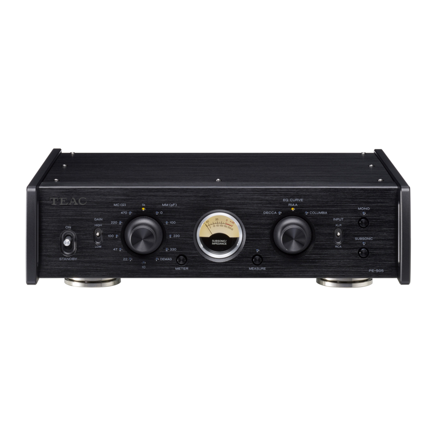
Front panel names and functions

 STANDBY/ON switch
Use to put the unit into standby mode or turn it on.
 GAIN switch
Use this to change the amplifier gain.
First, set it to LOW and check the volume. If the volume is too low, set it to HIGH. HIGH outputs with gain that is 12 dB higher compared to LOW.
 Impedance selection knob
Set the load impedance setting according to the cartridge type (MC/MM) used by the connected analog turntable.
- The indicator for the selected impedance lights.
- If the INPUT selection switch is set to XLR, MM cartridge settings cannot be selected. The XLR connectors are only for use with MC cartridges.
 METER button
Press this button to change the meter brightness in the following order.

 Meter
Meter
This shows the volume of subsonic (6 Hz and below) frequencies. During measurement, it shows MC cartridge impedance.
 MEASURE button
Use this to measure MC cartridge impedance.
- The indicator above the button lights during measurement.
- Playback sound is not output during impedance measurement.
 EQ CURVE selection knob
Select the curve that sounds natural according to the record being played back. The options are RIAA (curve for stereo LP playback), DECCA (DECCA LP) and COLUMBIA (Columbia LP).
 INPUT selection switch
Select which connectors are connected to the analog turntable.
 MONO button
Turn this on when using a mono cartridge.
- The indicator above this button lights when it is on.
 SUBSONIC filter button
When on, a filter is applied with a cutoff of 17 Hz and a slope of −24 dB/oct.
When playing a warped record, turning this on can reduce unnecessary woofer movement.
- The indicator above this button lights when it is on.
Basic operation
Turning the power on
- Minimize the volume of the amplifier.
If using a device that cannot have its volume adjusted when it is off, minimize the volume after turning it on. - Set the STANDBY/ON switch on the unit to ON.


- Play a record and adjust the volume on the amplifier.
- Use the EQ CURVE selection knob to select the curve that sounds natural depending on the record being played.
Putting the unit into standby
- If a record is being played, stop playback.
- Minimize the volume of the amplifier.
- Set the STANDBY/ON switch on the unit to STANDBY.

- Turn the amplifier off.

Setting the load impedance
When using an MC cartridge
If the MC cartridge used has a recommended load resistance (load impedance), set it to a value near that value. If not specified, select the value that provides the best sound quality. The lower the load resistance is, the lower the volume will be. Higher load resistances will increase the volume.
A standard load resistance is 100 Ω.
- This load resistance does not refer to the internal resistance of the cartridge (internal impedance, coil impedance).
- Select a load resistance that is high enough for the internal resistance of the cartridge being used.
- Selecting a load resistance that is not large enough relative to internal cartridge resistance will reduce sound volume and increase noise.
When using an MM cartridge
If the MM cartridge used has a recommended load capacity, try setting the knob to a position near that value. If not specified, select the value that provides the best sound quality.
MC cartridge impedance measurement
Use a 1kHz sine wave to measure the impedance of the entire path including the MC cartridge and the cable that connects the analog turntable and this device. Set the unit to receive a load impedance that is about twice the impedance determined from the measurement.
- Move the analog turntable tone arm away from the record.
- Press the MEASURE button and the indicator will light. o The meter will automatically switch to bright level.
- Read the impedance from the lower indications on the meter.
ATTENTION
- MM cartridge impedance and load capacity cannot be measured.
- Do not measure impedance during record playback.
- Playback sound is not output during impedance measurement.
Using the easy demagnetization function
Using the easy demagnetization function to demagnetize MC cartridges with iron cores and step-up transformers, for example, could improve the sound quality by making it clearer and giving it greater definition.
- Set the impedance selection knob to DEMAG.
The load impedance is set to 0 Ω and both ends of the cartridge are short-circuited. - Play a record.
The playback signal current goes through the cartridge and demagnetizes it.- Demagnetization takes about 30 seconds. Keep the record playing for about 30 seconds.
- Playback sound is not output when the impedance selection knob is set to DEMAG.
- Reset the impedance selection knob to its previous position.
Equalizer curve characteristics (time constant)
RIAA
3180 μs/318 μs/75 μs
Decca (DECCA LP)
1590 μs/318 μs/60 μs
Columbia (Columbia LP)
1590 μs/318 μs/100 μs
- There are a variety of opinions about equalizer curves.
- Try a different curve if the sound seems unnatural when using the RIAA curve to play an old record, even a stereo LP.
Automatic power saving function
This unit has an automatic power saving function.
- This is set to on when shipped new from the factory.
When the automatic power saving function is on
The unit will enter standby* if no operation occurs for about 30 minutes.
Operating the unit when in standby will disable the automatic power saving function and turn it on.
When the automatic power saving function is off
The unit will not enter standby automatically.
*Power consumption is 0.5 W or less when in standby.
Checking the setting
If automatic power saving is off, all the impedance indicators will light momentarily when the unit is turned on.
Setting the automatic power saving function
Use the following procedure to turn the automatic power saving function on and off.
While pressing the MEASURE button, set the STANDBY/ON switch to ON. Continue pressing the MEASURE button until all the indicators light (about three seconds).
Restoring default settings
While pressing the METER button, set the STANDBY/ON switch to ON. Continue pressing the METER button until all the indicators light (about three seconds).
Troubleshooting
If you experience a problem with this unit, please take a moment to review the following information before requesting service. If it still does not operate correctly, contact the retailer where you purchased the unit.
The unit does not turn on.
- Check that the power cord is completely plugged into the power outlet. If the outlet is switched, confirm that the switch is in the ON position.
- Connect a different electrical device to the outlet to confirm that it is supplying power.
- If the unit is in standby because of the automatic power saving function, set the STANDBY/ON switch to STANDBY once and then set it to ON again.
There is a humming noise.
- If a connecting cable is near a power cord, fluorescent light or similar cause of interference, increase the distance between them as much as possible.
- Check the cable connecting the analog turntable to the grounding terminal (FRAME GND) on this unit.
- Whether or not there is a grounded connection with the analog turntable can affect how noise is heard.
No sound is output.
- If a stereo amplifier is connected to this unit, adjust the volume on the amplifier.
- If the indicator above the MEASURE button is lit, press the MEASURE button to turn it off.
- Check the load impedance setting.
- Reconfirm the connections between equipment.
Sound is odd or breaks up.
- Check the connectors connected to the amplifier. Connect this unit to the LINE IN or other audio input connectors on the amplifier.
- Check the load impedance setting.
- Set the GAIN switch to LOW.
- When connected to an analog turntable that has a built-in phono equalizer amplifier, turn off the output of the phono equalizer amplifier.
Volume is low.
- Check the load impedance setting.
- Set the GAIN switch to HIGH.
The white noise level is too high.
- Check the audio cables connected to the analog turntable.
- When using an MC cartridge, the load impedance setting can affect the noise sound.
Since this unit uses a microcontroller, external noise and other interference can cause the unit to malfunction. If this occurs, unplug the power cord, wait for a while, and then turn the unit on again and restart operations.
Specifications
Inputs
RCA connectors: 1 pair (for MC/MM)
XLR connectors: 1 pair (for MC)
Input impedance
MC: 10 Ω, 22 Ω, 47 Ω, 100 Ω, 220 Ω, 470 Ω, 1 kΩ (switchable using setting knob)
MM: 47 kΩ
Load capacity: 0 pF, 100 pF, 220 pF, 330 pF (switchable using setting knob)
Outputs
RCA connectors: 1 pair
XLR connectors: 1 pair
Output impedance
RCA connectors: 63 Ω
XLR connectors: 126 Ω
Audio performance
Rated output voltage
RCA output: 2 Vrms
XLR output: 4 Vrms
RIAA deviation (20 Hz – 20 kHz): ±0.05 dB
Total harmonic distortion
Rated output, 1 kHz, GAIN LOW
RCA input (MM): 0.002%
RCA input (MC): 0.02%
XLR input (MC): 0.02%
Residual noise voltage (input shorted, GAIN LOW, IHF-A)
RCA input (MM): 10 µV
RCA input (MC): 65 µV
XLR input (MC): 85 µV
S/N ratio (input shorted, rated output, GAIN LOW, IHF-A)
RCA input (MM): 106 dB
XLR input (MC): 86 dB
Channel separation (MM, 10 kHz, GAIN LOW): −90 dB or higher
Gain
GAIN LOW
RCA input (MM): 34 dB
RCA input (MC): 54 dB
XLR input (MC): 54 dB
GAIN HIGH
RCA input (MM): 46 dB
RCA input (MC): 66 dB
XLR input (MC): 66 dB
Subsonic filter: 17 Hz, −24 dB/octave
Maximum permissible input voltage (distortion 0.1%, GAIN LOW)
RCA input (MM): 150 mV
RCA input (MC): 16 mV
XLR input (MC): 16 mV
General
Power supply
Model for Europe: AC 220–240 V, 50/60 Hz
Model for USA/Canada: AC 120 V, 60 Hz
Power consumption: 14 W
External dimensions (W × H × D, including protrusions):
290 × 84.5 × 252.5 mm (11 1/2" × 3 3/8" × 10")
Weight: 4.5 kg (10 lb)
Included accessories
Power cord × 1
Rubber pads × 3
Owner's manual (this document, including warranty) × 1
- Specifications and appearance are subject to change without notice.
- Weight and dimensions are approximate.
- Illustrations in this owner's manual might differ slightly from production models.
XLR cable connection diagrams
When using XLR cables with this unit, use one of the following types of connections.
Type 1

Type 2

IMPORTANT SAFETY INSTRUCTIONS

RISK OF ELECTRIC SHOCK
DO NOT OPEN
TO REDUCE THE RISK OF ELECTRIC SHOCK, DO NOT REMOVE COVER (OR BACK). NO USERSERVICEABLE PARTS INSIDE. REFER SERVICING TO QUALIFIED SERVICE PERSONNEL.
 The lightning flash with arrowhead symbol, within an equilateral triangle, is intended to alert the user to the presence of uninsulated "dangerous voltage" within the product's enclosure that may be of sufficient magnitude to constitute a risk of electric shock to persons.
The exclamation point within an equilateral triangle is intended to alert the user to the presence of important operating and maintenance (servicing) instructions in the literature accompanying the appliance.

TO PREVENT FIRE OR SHOCK HAZARD, DO NOT EXPOSE THIS APPLIANCE TO RAIN OR MOISTURE.

- DO NOT REMOVE THE EXTERNAL CASES OR CABINETS TO EXPOSE THE ELECTRONICS. NO USER SERVICEABLE PARTS ARE INSIDE.
- IF YOU ARE EXPERIENCING PROBLEMS WITH THIS PRODUCT, CONTACT THE STORE WHERE YOU PURCHASED THE UNIT FOR A SERVICE REFERRAL. DO NOT USE THE PRODUCT UNTIL IT HAS BEEN REPAIRED.
- USE OF CONTROLS OR ADJUSTMENTS OR PERFORMANCE OF PROCEDURES OTHER THAN THOSE SPECIFIED HEREIN MAY RESULT IN HAZARDOUS RADIATION EXPOSURE.
- Read these instructions.
- Keep these instructions.
- Heed all warnings.
- Follow all instructions.
- Do not use this apparatus near water.
- Clean only with dry cloth.
- Do not block any ventilation openings. Install in accordance with the manufacturer's instructions.
- Do not install near any heat sources such as radiators, heat registers, stoves, or other apparatus (including amplifiers) that produce heat.
- Do not defeat the safety purpose of the polarized or grounding-type plug. A polarized plug has two blades with one wider than the other. A grounding type plug has two blades and a third grounding prong. The wide blade or the third prong are provided for your safety. If the provided plug does not fit into your outlet, consult an electrician for replacement of the obsolete outlet.
- Protect the power cord from being walked on or pinched particularly at plugs, convenience receptacles, and the point where they exit from the apparatus.
- Only use attachments/accessories specified by the manufacturer.
![]()
Use only with the cart, stand, tripod, bracket, or table specified by the manufacturer, or sold with the apparatus. When a cart is used, use caution when moving the cart/apparatus combination to avoid injury from tip-over.- Unplug this apparatus during lightning storms or when unused for long periods of time.
- Refer all servicing to qualified service personnel. Servicing is required when the apparatus has been damaged in any way, such as power-supply cord or plug is damaged, liquid has been spilled or objects have fallen into the apparatus, the apparatus has been exposed to rain or moisture, does not operate normally, or has been dropped.

- The apparatus draws nominal non-operating power from the AC outlet with its POWER or STANDBY/ON switch not in the ON position.
- The mains plug is used as the disconnect device; the disconnect device shall remain readily operable.
- Caution should be taken when using earphones or headphones with the product because excessive sound pressure (volume) from earphones or headphones can cause hearing loss.
- Do not expose this apparatus to drips or splashes.
- Do not place any objects filled with liquids, such as vases, on the apparatus.
- The handle-like parts on the left and right sides of the front panel are decorative. Do not put your fingers through them or use them to carry the unit.
- Do not install this apparatus in a confined space such as a book case or similar unit.
- The apparatus should be located close enough to the AC outlet so that you can easily reach the power cord plug at any time.
- If the product uses batteries (including a battery pack or installed batteries), they should not be exposed to sunshine, fire or excessive heat.
- CAUTION for products that use replaceable lithium batteries: there is danger of explosion if a battery is replaced with an incorrect type of battery. Replace only with the same or equivalent type.
Products with Class I construction are equipped with a power supply cord that has a grounding plug. The cord of such a product must be plugged into an AC outlet that has a protective grounding connection.
IN USA/CANADA, USE ONLY ON 120V SUPPLY.
The nameplate is located on the bottom of the unit as shown below.

Using the TEAC Global Site
You can download updates for this unit from the TEAC Global Site: https://teac-global.com
In the TEAC Downloads section, click the desired language to open the Downloads website page for that language.
Documents / Resources
References
Download manual
Here you can download full pdf version of manual, it may contain additional safety instructions, warranty information, FCC rules, etc.
Advertisement


Need help?
Do you have a question about the PE-505 and is the answer not in the manual?
Questions and answers