Advertisement
Included accessories
Check to be sure the box contains all the included items shown below.
Please contact the store where you purchased this unit if any of these items are missing or have been damaged during transportation.
- Power cord × 1
- Rubber pads × 3
- Owner's manual (this document, including warranty) × 1
Maintenance
Wipe dirt from the top cover and other panel surfaces using a soft cloth that has been slightly dampened with a diluted neutral cleanser.
Do not wipe with chemical cleaning cloths, thinner or other chemical agents. Doing so could damage the surface.
 For your safety, disconnect the power cord from the outlet before cleaning.
Using the TEAC Global Site
You can download updates for this unit from the TEAC Global Site: http://teac-global.com/
In the TEAC Downloads section, click the desired language to open the Downloads website page for that language.
Before use
Placement precautions
- Place the unit in a stable location near the audio system that you will use with it.
- Do not install this unit in a location that could become hot. This includes places that are exposed to direct sunlight or near a radiator, heater, stove or other heating equipment. Moreover, do not place it on top of an amplifier or other equipment that generates heat. Doing so could cause discoloration, deformation or malfunction.
Also avoid locations that are subject to vibrations or exposed to excessive dust, cold or moisture. - When installing this unit, leave a little space (at least 3 cm or 1") between it and walls and other devices in order to allow good heat dissipation.
If you put it in a rack, for example, leave at least 5 cm (2") open above it and at least 10 cm (4") open behind it. Failure to provide these gaps could cause heat to build up inside and result in fire. - You may stack this unit with a PD-501HR, NT-505 or other 501/503/505 series units. However, if heat should cause the protection circuit to be activated and sound output stops suddenly, place this unit on top and with sufficient distance between it and walls and other devices in order to improve heat dissipation.
- Do not place CDs, CD-Rs, cassette tapes, other audio equipment or other items that are susceptible to heat on top of the unit. Doing so could damage these items.
- Do not put cloth on top of the unit or place the unit on top of bedding or thick carpets. Doing so could cause the unit to overheat and damage it.
- Do not move the unit during use.
- The voltage supplied to the unit should match the voltage printed on the bottom of the unit. If you are in any doubt regarding this matter, consult an electrician.
- Do not open the body of the unit as this might result in damage to the circuitry or cause electric shock. If a foreign object should get into the unit, contact your dealer.
- When removing the power plug from the wall outlet, always pull directly on the plug; never yank on the cord.
Note about pinpoint feet
High-precision metal pinpoint feet are attached firmly to the bottom plate of this unit.
The stands for these feet are loose, but when the unit is placed in position, it is supported by these pinpoint feet, which will effectively disperse vibrations.

- The included rubber pads are intended to protect the surface where the unit is placed. Apply them to the bottoms of the foot-stands.
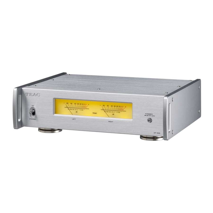
Front panel names and functions

- STANDBY/ON switch
Use to put the unit into standby mode or turn it on. - Level meters
These show the output levels. - DIMMER/METER GAIN button
The brightness of the level meters changes each time you press this button.
Press and hold this button for three seconds to change level meter operation.
By using this button together with the STANDBY/ON switch, you can change the automatic power saving setting and restore various settings to their factory default values.
Rear panel names and functions

- Analog audio input (INPUTS) connectors
Use these to input stereo analog audio. Connect these connectors to the audio output connectors of a preamplifier or another device such as a DAC that has a preamplifier function.- This unit's XLR connectors are 2: HOT.
Use commercially-available audio cables for connections.
RCA: RCA cables
XLR: XLR cables
Using with STEREO output mode
Connect this unit's R input connector to the R output connector of the audio output device, and this unit's L input connector to the L output connector of the other device.
Using with BI-AMP or BTL output mode
Connect this unit's L connector to the L or R connector of the audio output device. The R connector of this device is not used.
- INPUT SELECTOR switch
Use this to switch between input sources.
![warning]() Do not switch this when the unit is on.
Do not switch this when the unit is on.
Failure to do so could result in sudden loud noises that could damage speakers and harm your hearing. - OUTPUT MODE switch
This sets the output mode.
STEREO: stereo power amplifier
BI-AMP: mono bi-amplifier
BTL: mono power amplifier
![warning]() Always disconnect speakers before changing the output mode. Reconnect the speakers after changing the mode.
Always disconnect speakers before changing the output mode. Reconnect the speakers after changing the mode. - SPEAKERS terminals
This unit supports speakers that have a nominal impedance of
4 Ω – 16 Ω when the output mode is STEREO or BI-AMP and
8 Ω – 16 Ω when BTL.
Use commercially-available speaker cables to connect the speakers. - Power inlet (~IN)
Connect the supplied power cord here.
After all other connections are complete, connect the power cord's plug to a wall outlet.
![warning]() Do not use any power cord other than the one included with this unit. Use of other power cords could result in fire or electric shock.
Do not use any power cord other than the one included with this unit. Use of other power cords could result in fire or electric shock.
![warning]() Unplug the cord from the outlet when not using the unit for a long time.
Unplug the cord from the outlet when not using the unit for a long time. - Maintenance port
This is used for maintenance. Do not connect anything to this port unless instructed to do so by our service department.
Connecting speakers
Notes about speaker cables
- Use commercially-available speaker cables to connect the speakers.
- Use the shortest speaker cables possible. The longer the cable, the greater the resistance value and the more that damping performance is reduced. Moreover, length also increases inductance and capacitance, degrading the sound quality of high frequencies.
- Use left and right speaker cables that have the same length.
Precautions when connecting speakers
- Connect the power plugs after all connections have been made.
- Carefully read the manuals of the devices that you are connecting and follow their instructions when making connections.
- When the left and right grounds are shared in a sub woofer with a built-in amplifier, for example, use might not be possible depending on connection conditions.
ATTENTION
- This unit supports speakers that have a nominal impedance of 4 Ω – 16 Ω when the output mode is STEREO or BI-AMP and 8 Ω – 16 Ω when BTL. If speakers with lower impedance ratings are used, the protection circuit could operate, causing sound output to stop. In some cases, their use could even cause damage to this unit or the speakers.
- This unit's red terminal is positive (
![]() ) and its black terminal is negative (
) and its black terminal is negative (![]() ). Generally, the
). Generally, the ![]() wire of the speaker cable is marked to distinguish it from the
wire of the speaker cable is marked to distinguish it from the ![]() wire of the cable. Connect the marked wire to the red
wire of the cable. Connect the marked wire to the red ![]() terminal and the unmarked wire to the black
terminal and the unmarked wire to the black ![]() terminal.
terminal. - If the exposed end of a core wire in a speaker cable contacts another cable or terminal, a short could occur.
- Never allow speaker cables to cause a short.
- To prevent hum and noise, avoid bundling the cables together with the AC power cord or other cables.
 ) and its black terminal is negative (
 ). Generally, the
 How to connect speakers
- Remove about one centimeter (1/2") of insulation from the end of the speaker cable and twist the core wires well.
- Turn the terminal cap counterclockwise to loosen it.
- Insert the wire into the hole in the terminal post and turn the terminal cap clockwise to securely connect it.
![]()
Connect it so that none of the wire insulation is touching the terminal. - Confirm that the cable is fastened securely by gently pulling the cable.

Connecting with banana plugs
You can also make connections using commercially-available banana plugs. First, connect the banana plugs to the speaker cables and then connect the plugs to the terminals.
- Keep the caps tightened when in use.
- Carefully read the instructions for the banana plugs that you are using.
ATTENTION
Notice about the European model
In accordance with European safety regulations, connecting banana plugs to speaker terminals is not allowed on European models.
The holes into which banana plugs could be inserted have been covered with black caps. Connect speakers using bare wires or spade lugs.
If a black cap should become separated from its terminal, return it to its original position.
Connections

This unit does not have a volume adjustment function. Connect this unit to a preamplifier or another device such as a DAC that has a preamplifier function, and use that device to adjust the volume. If you connect this unit to a device that cannot be used to adjust the output volume, you will not be able to adjust the volume during playback. Sound might be output from the speakers at a very loud volume, which could harm hearing or damage equipment.

- When connecting this unit to a UD-505, NT-505, UD-503 or NT-503, set the LINE OUT LEVEL to VARIABLE.
- The use of this unit's two built-in amplifier channels depends on the OUTPUT MODE switch setting.
Connection examples for each mode are provided below.
Complete all other connections before setting the STANDBY/ON switch to ON.
- Carefully read the manuals of the devices that you are connecting and follow their instructions when making connections.
- Do not bundle connecting cables with power cords. Doing so could cause noise.
- Connect all plugs completely.
Using STEREO output mode
Set the OUTPUT MODE switch to STEREO.
Connection example

Using BI-AMP output mode
This unit can be used as a mono bi-amplifier.
Set the OUTPUT MODE switches on the units for the L and R channels to BI-AMP.
In BI-AMP mode, use two of these units for stereo playback.
What is bi-amp connection?
This method operates amplifiers independently for low-frequency and high-frequency speaker units.
NOTE
- Sound input through the analog audio INPUTS L connector will be output from both the L and R SPEAKERS connectors.
- Sound input through the analog audio INPUTS R connector will not be output from the SPEAKERS connectors.
ATTENTION
- Bi-amplification is not possible with speakers that do not have both low and high frequency connectors.
- When using bi-amp connections, remove speaker terminal links and disconnect the connections between speaker
![]() connectors and between
connectors and between ![]() connectors.
connectors.
Connection example

Using BTL output mode
This unit can be used as a mono BTL amplifier.
Set the OUTPUT MODE switches on the units for the L and R channels to BTL.
In BTL mode, use two of these units for stereo playback.
What is BTL connection?
Two amplifier channels are used to drive the speaker for one channel. This is effective to realize high output for speakers with high impedance.
NOTE
- Sound input through the analog audio INPUTS L connector will be output from both the L and R SPEAKERS connectors.
- In BTL mode, sound input through the analog audio INPUTS R connector will not be output from the SPEAKERS connectors.
ATTENTION
- Do not connect anything to the SPEAKERS - output connectors.
Connection example

Basic operation
In order to protect the speakers, turn the power for systems that this unit is connected to on and off in the following order.
NOTE
This explanation assumes that a preamplifier is connected to this unit.
When connecting a UD-505, NT-505, UD-503 or NT-503
Set the LINE OUT LEVEL to VARIABLE on the UD-505, NT-505, UD-503 or NT-503 in advance.
NOTE
- The UD-505, NT-505, UD-503 and NT-503 are equivalent to preamplifiers.
- When using a UD-505, NT-505, UD-503 or NT-503 as a USB DAC or using an NT-505 or NT-503 as a network player, it functions as a preamplifier and a source device.
Connection example

Turning the power on
- Minimize the volume of the preamplifier.
If using a device that cannot have its volume adjusted when it is off, minimize the volume after turning it on. - Turn the source device on.
- Turn the preamplifier on.
- Turn this unit on.

The level meters will blink and the mute function will turn on. When the amplifier operation stabilizes, they will light and the mute function will turn off. - Start playback on the source device, and adjust the volume on the preamplifier.
Adjust the preamplifier volume after the level meters on this unit stop blinking and stay lit.

Turning the power off
- If a connected device is playing back, stop playback.
- Minimize the volume of the preamplifier.
- Put the unit into standby mode.

- Turn the preamplifier off.
- Turn the source device off.

Dimmer
You can change the brightness of the level meters. Press the DIMMER/METER GAIN button to cycle through the brightness settings in the following order.

Changing level meter operation
Press and hold the DIMMER/METER GAIN button for three seconds to cycle through the following operation modes.

- When level meter operation is +20 dB, needle movement will be greater than usual.
Automatic power saving function
This unit has an automatic power saving function. If the automatic power saving function is set to on, the unit will automatically enter standby mode if there is no audio input for about 30 minutes.
Turning automatic power saving on and off
- While pressing the DIMMER/METER GAIN button, set the STANDBY/ON switch to ON.
- Immediately after setting the STANDBY/ON switch to ON, release the DIMMER/METER GAIN button.


Releasing the DIMMER/METER GAIN button will switch the automatic power saving function between on and off and the level meters will blink.
You can check the automatic power saving setting by the blinking of the level meters at this time.
Automatic power saving function on
Meters blink every 3 seconds.
Automatic power saving function off
After blinking twice at 0.4-second intervals, meters continue to alternately become lit and unlit at 3-second intervals.
Restoring default settings
- While pressing the DIMMER/METER GAIN button, set the STANDBY/ON switch to ON.
- When the level meters blink, release the DIMMER/METER GAIN button.


The factory default settings will be restored, and after the level meters blink twice at 0.4-second intervals, the unit will enter standby.
Troubleshooting
If you experience a problem with the unit, please take a moment to review the following information before requesting service. If it still does not operate correctly, contact the retailer where you purchased the unit.
The unit does not turn on.
- Check that the power cord is completely plugged into the power outlet. If the outlet is switched, confirm that the switch is in the ON position.
- Connect a different electrical device to the outlet to confirm that it is supplying power.
Noise occurs.
- Place the unit as far away as possible from TVs, microwave ovens and other devices that have strong magnetism.
There is a humming noise.
- If a connecting cable is near a power cord, fluorescent light or similar cause of interference, increase the distance between them as much as possible.
No sound is output.
- Use the preamplifier volume knob to adjust the volume.
- Use the preamplifier input knob to select the source that you want to hear.
- Reconfirm the connections with other equipment.
- Check the INPUT SELECTOR switch setting on the back of the unit.
The level meter lights are blinking and no sound is output.
- The
![]() and
and ![]() speaker cables might have shorted. Set the STANDBY/ON switch to STANDBY, and check the speaker connections.
speaker cables might have shorted. Set the STANDBY/ON switch to STANDBY, and check the speaker connections.
 and
and  speaker cables might have shorted. Set the STANDBY/ON switch to STANDBY, and check the speaker connections.
Sound output stops suddenly and the level meter lights are blinking.
- The protection circuit might have activated due to high temperature, excessive load or another cause. Set the STANDBY/ ON switch to STANDBY, check the power and speaker connections, and wait several minutes before setting it to ON again. If this unit is becoming hot, increase the amount of space between it and walls and other devices to increase the dissipation of heat.
Automatic power saving caused the unit to enter standby.
- Set the STANDBY/ON switch to STANDBY once and then set it to ON again.
Specifications
Amplifier
| Maximum effective output | |
| STEREO or BI-AMP operation | 170 W + 170 W (4 Ω, 1 kHz, JEITA) 95 W + 95 W (8 Ω, 1 kHz, JEITA) |
| BTL operation | 350 W (8 Ω, 1 kHz, JEITA) |
| Rated output | |
| STEREO or BI-AMP operation | 125 W + 125 W (4 Ω, THD 0.8%, 1 kHz) 70 W + 70 W (8 Ω, THD 0.8%, 1 kHz) |
| BTL operation | 230 W (8 Ω, THD 0.8%, 1 kHz) |
| Allowable speaker impedance | |
| STEREO or BI-AMP operation | 4–16 Ω |
| BTL operation | 8–16 Ω |
| Total harmonic distortion | 0.0015% (8 Ω, 1 kHz, 12.5 W, JEITA) |
| S/N ratio (input short) | 113 dB (8 Ω, 1 kHz, IHF-A) |
| Frequency response | 10 Hz – 50 kHz (+0 dB, −5 dB) (8 Ω, 1 kHz, 1 W, JEITA) |
| Input sensitivity | |
| RCA connectors | 0.66 V (with 8Ω output, THD 1%) |
| XLR connectors | 1.3 V (with 8Ω output, THD 1%) |
| Input impedance | |
| RCA connectors | 10 kΩ or more |
| XLR connectors | 10 kΩ or more |
General
| Power supply | ||
| Model for Europe | AC 220–240 V, 50/60 Hz | |
| Model for USA/Canada | AC 120 V, 60 Hz | |
| Power consumption | ||
| Models for Europe and USA/Canada | 58 W | |
| External dimensions (W × H × D, including protrusions) | 290 × 84.5 × 271 mm (11 1/2" × 3 3/8" × 10 3/4") | |
| Weight | 4.4 kg (9 3/4 lb) | |
| Operating temperature range | +5°C to +35°C | |
| Operating humidity range | 5% – 85% (no condensation) | |
| Storage temperature range | −20°C to +55°C | |
Included accessories
Power cord × 1
Rubber pads × 3
Owner's manual (including warranty) × 1
- Design and specifications are subject to change without notice.
- Weight and dimensions are approximate.
- Illustrations in this manual might differ slightly from production models.
IMPORTANT SAFETY INSTRUCTIONS

RISK OF ELECTRIC SHOCK
DO NOT OPEN
TO REDUCE THE RISK OF ELECTRIC SHOCK, DO NOT REMOVE COVER (OR BACK). NO USER SERVICEABLE PARTS INSIDE. REFER SERVICING TO QUALIFIED SERVICE PERSONNEL.
 The lightning flash with arrowhead symbol, within an equilateral triangle, is intended to alert the user to the presence of uninsulated "dangerous voltage" within the product's enclosure that may be of sufficient magnitude to constitute a risk of electric shock to persons.
The exclamation point within an equilateral triangle is intended to alert the user to the presence of important operating and maintenance (servicing) instructions in the literature accompanying the appliance.

TO PREVENT FIRE OR SHOCK HAZARD, DO NOT EXPOSE THIS APPLIANCE TO RAIN OR MOISTURE.
- DO NOT REMOVE THE EXTERNAL CASES OR CABINETS TO EXPOSE THE ELECTRONICS. NO USER SERVICEABLE PARTS ARE INSIDE.
- IF YOU ARE EXPERIENCING PROBLEMS WITH THIS PRODUCT, CONTACT THE STORE WHERE YOU PURCHASED THE UNIT FOR A SERVICE REFERRAL. DO NOT USE THE PRODUCT UNTIL IT HAS BEEN REPAIRED.
- USE OF CONTROLS OR ADJUSTMENTS OR PERFORMANCE OF PROCEDURES OTHER THAN THOSE SPECIFIED HEREIN MAY RESULT IN HAZARDOUS RADIATION EXPOSURE.
- Read these instructions.
- Keep these instructions.
- Heed all warnings.
- Follow all instructions.
- Do not use this apparatus near water.
- Clean only with dry cloth.
- Do not block any ventilation openings. Install in accordance with the manufacturer's instructions.
- Do not install near any heat sources such as radiators, heat registers, stoves, or other apparatus (including amplifiers) that produce heat.
- Do not defeat the safety purpose of the polarized or grounding-type plug. A polarized plug has two blades with one wider than the other. A grounding type plug has two blades and a third grounding prong. The wide blade or the third prong are provided for your safety. If the provided plug does not fit into your outlet, consult an electrician for replacement of the obsolete outlet.
- Protect the power cord from being walked on or pinched particularly at plugs, convenience receptacles, and the point where they exit from the apparatus.
- Only use attachments/accessories specified by the manufacturer.
![]()
Use only with the cart, stand, tripod, bracket, or table specified by the manufacturer, or sold with the apparatus. When a cart is used, use caution when moving the cart/apparatus combination to avoid injury from tip-over.- Unplug this apparatus during lightning storms or when unused for long periods of time.
- Refer all servicing to qualified service personnel. Servicing is required when the apparatus has been damaged in any way, such as power-supply cord or plug is damaged, liquid has been spilled or objects have fallen into the apparatus, the apparatus has been exposed to rain or moisture, does not operate normally, or has been dropped.

- The apparatus draws nominal non-operating power from the AC outlet with its POWER or STANDBY/ON switch not in the ON position.
- The mains plug is used as the disconnect device; the disconnect device shall remain readily operable.
- Caution should be taken when using earphones or headphones with the product because excessive sound pressure (volume) from earphones or headphones can cause hearing loss.
- Do not expose this apparatus to drips or splashes.
- Do not place any objects filled with liquids, such as vases, on the apparatus.
- Do not install this apparatus in a confined space such as a book case or similar unit.
- The apparatus should be located close enough to the AC outlet so that you can easily reach the power cord plug at any time.
- If the product uses batteries (including a battery pack or installed batteries), they should not be exposed to sunshine, fire or excessive heat.
![]()
for products that use replaceable lithium batteries: there is danger of explosion if a battery is replaced with an incorrect type of battery. Replace only with the same or equivalent type.
Products with Class! construction are equipped with a power supply cord that has a grounding plug. The cord of such a product must be plugged into an AC outlet that has a protective grounding connection.
IN USA/CANADA, USE ONLY ON 120V SUPPLY.
The nameplate is located on the bottom of the unit as shown below.
Front side

Documents / Resources
References
Download manual
Here you can download full pdf version of manual, it may contain additional safety instructions, warranty information, FCC rules, etc.
Advertisement


Need help?
Do you have a question about the AP-505 and is the answer not in the manual?
Questions and answers