Table of Contents
Advertisement
Quick Links
Dedicated Driver Card for PM380/427VS
CBV30
Driver
〈 User Manual 〉
Read this manual before use
Thank you for purchasing CBV30
(hereinafter referred to as "this product").
Applicable MDR Model
・ PM380VS, PM427VS
For more details on PM380/427VS, download the user manual from ITOH DENKI
web page.
ITOH DENKI
https://itohdenki.co.jp/english/support/manual.html
Before using this product, carefully read this user manual and fully
understand the content.
Keep this document readily accessible for future reference.
Home > Download/Support > User Manual
ITOH DENKI
ITOH DENKI
ITOH DENKI
Driver card
No.661
Advertisement
Table of Contents

Related Manuals for ITOH DENKI CBV30


Summary of Contents for ITOH DENKI CBV30
- Page 1 Before using this product, carefully read this user manual and fully understand the content. Keep this document readily accessible for future reference. For more details on PM380/427VS, download the user manual from ITOH DENKI web page. Home > Download/Support > User Manual ITOH DENKI...
-
Page 2: Introduction
ITOH DENKI. There are some examples of parts that need to be prepared by customers, as Notes on industrial explained within this manual. -
Page 3: Procedures From Installation To Operation
Procedures from installation to operation CBV30 User Manual 2. Procedures from installation to operation Procedures from installation to operation Read this manual Start using only after you have understood the product’ s functions, and safety precautions. Advance preparation Prepare the 24 VDC power supply, such as DC power supply units. -
Page 4: Table Of Contents
INDEX CBV30 User Manual INDEX Introduction …… 2 Procedures from installation to operation …… 3 Safety precautions …… 5 3-1. General precautions …… 7 3-2. Precautions on installation …… 8 3-3. Precautions on wiring …… 9 3-4. Precautions related to control …… 9 3-5. Precautions on maintenance and inspection …… 10... -
Page 5: Safety Precautions
3. Safety precautions CBV30 User Manual 3. Safety precautions Refer to 5. Check Product (P.17) for parts name. -
Page 6: Symbol Explanation
Danger level CBV30 User Manual 3. Safety precautions Danger level To prevent hazards to users and/or others, and/or damage to property in advance, we explain important precautions to be followed securely as below. ■ We categorize the degree of hazard and/or damage that may result if a user disregards the description, and operates the product improperly, using and... -
Page 7: General Precautions
General precautions CBV30 User Manual 3. Safety precautions 3-1. WARNING General precautions Do not use the product near places subject to explosive, flammable gas, and/or corrosive atmosphere, and/or combustible materials. Failure to follow this could result in explosion, fire, electric shock and/or injury. -
Page 8: Precautions On Installation
General precautions CBV30 User Manual 3. Safety precautions 3-1. CAUTION General precautions Do not turn on/off relays and/or contactors near power cables, signal cables, and/or driver cards. Failure to follow this could result in malfunction due to noise generation. LED or Pull-up/Pull-down circuits implemented in the output circuit of control devices could result in unexpected operation. -
Page 9: Precautions On Wiring
Precautions on wiring CBV30 User Manual 3. Safety precautions 3-3. CAUTION Precautions on wiring Wire when the power is shut off. Failure to follow this could result in electric shock and/or accidents due to unexpected operation. Be sure to shut off power before inserting or removing any connectors. -
Page 10: Precautions On Maintenance And Inspection
Precautions on maintenance and inspection CBV30 User Manual 3. Safety precautions 3-5. WARNING Precautions on maintenance and If any abnormalities are found, do not use this product inspection until the causes have been eliminated completely . Using this product with unattended abnormalities could result in not only damage to the devices, but also unexpected accidents. -
Page 11: Advance Preparation
4. Advance preparation CBV30 User Manual 4. Advance preparation... - Page 12 The other devices need to be prepared CBV30 User Manual 4. Advance preparation Wiring image AC power Controller, such as PLC Breaker Safety circuit 24V DC power supply unit CBV30 ■ As for the sensor input, and input/output signals of driver cards, adopt the number of inputs/outputs based on operation. ■ The safety circuit includes the emergency stop equipment and magnet contactor.
- Page 13 The other devices need to be prepared CBV30 User Manual 4. Advance preparation The other devices Before introducing this product, prepare the following devices separately. need to be prepared ① 24V DC power supply Power supply equipment to supply 24V DC to this product ● Switching power supply (24V DC) 3A 72W or more per MDR ●...
- Page 14 The other devices need to be prepared CBV30 User Manual 4. Advance preparation ② MDR PM380/427VS ③ Control devices Devices to control this product, such as PLC ④ Safety relay 〈Available wire diameter for driver card connectors〉 ⑤Wiring materials Necessary for wiring of power and signal Connector CBV30...
- Page 15 5. Check Product CBV30 User Manual 4. Advance preparation ⑦ Emergency stop This product does not include the emergency stop equipment. equipment Customers must make sure to install it. To this product Emergency stop equipment AC power 24V DC power supply unit Safety circuit...
-
Page 16: Check Product
Checking the model CBV30 User Manual 5. Check Product... -
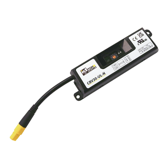
Page 17: Checking Appearance
Checking the model CBV30 User Manual 5. Check Product Checking the model Unpack the product, and check that the product model is what you ordered. CBV30ーULーN Input and output signals ・ N … NPN input and output signals ・ P … PNP input and output signals... -
Page 18: Installation/Wiring
6. Installation/Wiring CBV30 User Manual 6. Installation/Wiring... -
Page 19: Preparation To Install Driver Cards
Install driver cards CBV30 User Manual 6. Installation/Wiring 6-1. Preparation for install Hole processing on frames or control panel driver cards Makes mounting holes on the frames or control panel by reference to the mounting holes for driver cards. ■ Mount driver cards on a flat surface where heat can be released easily. - Page 20 CBL-402 Functions list / Wiring CBV30 User Manual 6. Installation/Wiring Connector descriptions (Power supply) 24V DC Functions Application STTS STATUS (Signal output) (Control) Switching of the direction of rotation Start / Stop (RUN / STOP) Connect the 24V DC and 0 V cables to CN1 (2 contacts).
-
Page 21: I/O Circuit
I/O Circuit CBV30 User Manual 6. Installation/Wiring 6-4. I/O Circuit RUN_IN DIR_IN STTS OUT 5.1kΩ 5.1kΩ +24V Polyswitch Open Drain output 3 STTS OUT Open Drain output * Set up a protective resistor so that the current flowing STATUS OUT will be 25 mA or lower. -
Page 22: Control/Operation
7. Control/Operation CBV30 User Manual 7. Control/Operation... -
Page 23: Switching Brake Type
Rotate direction setting CBV30 User Manual 7. Control/Operation 7-1. The MDR’s direction of rotation is determined by a combination of SW1#1 and CN2. Rotate direction setting SW1#1 SW1#1 INPUT:24V , 1.6A OUTPUT:24Vp-p, 1.4A CN2# 3∅, 194Hz(0Hz〜199Hz) The transfer direction cannot be ■ changed using SW1#1 while the MDR is running. -
Page 24: Maintenance/Inspection
8. Maintenance/Inspection CBV30 User Manual 8. Maintenance/Inspection... -
Page 25: Error Details
Error details on CBV30 CBV30 User Manual 8. Maintenance/Inspection 8-1. Error details on CBV30 Error details Errors can be checked by PWR (Green), ERR (Red), and signals from CN2#3. ■ When error signals have been released using CN2#1 (RUN / STOP), the MDR instantly starts up when RUN is input. -
Page 26: Troubleshooting
⇒ Check the wire size and wirings. • Check if CBV30 is too far from the power supply. (Check if the voltage is dropped.) • Check if the product is used in the ambient temperature range between 0 and 40 degree. -
Page 27: Specifications
Specifications CBV30 User Manual Specifications... -
Page 28: Product Specifications
Product specifications CBV30 User Manual Specifications Product specifications Model CBV30 Power supply voltage 24V DC±10% Rated voltage 24V DC Static current 0.05A Starting current 2.6A±0.2A 20A(1msec) Peak current Power connector WAGO734-102 Wire diameter: 0.8 to 1.5 mm Wire (CN1) diameter Control connector WAGO733-103 Wire diameter: 0.08 to 0.5 mm... -
Page 29: Detailed Characteristics Of The Specified Speed
Detailed characteristics of the specified speed CBV30 User Manual Specifications Detailed characteristics of the specified speed PM380VS Nominal speed 17m/min Current(A) Speed vs Tangential Force Speed(m/min) Tangential Force(N) Current vs Tangential Force Power Output Power Input No-load Rated Starting No-load Starting (W) (W)... - Page 30 Tel: +33 4 50 03 09 99 Fax: +33 4 50 03 07 60 www.itoh-denki.com North & South Americas ■ ITOH DENKI USA, INC 2 Great Valley Blvd., Wilkes-Barre, PA 18706-5332 U.S.A. Tel: +1 570 820 8811 Fax: +1 570 820 8838 www.itohdenki.com Mainland China ■ ITOH DENKI SHANGHAI CO., LTD. Room 1812, No.689, Guangdong Rd., Huangpu district, Shanghai 200001, P.R. China Tel: +86 21 6341 0181 Fax: +86 21 6341 0180 www.itohdenki.com.cn https://www.itohdenki.co.jp Specifications or appearance of product are subject to change without prior notice. Ver.
Need help?
Do you have a question about the CBV30 and is the answer not in the manual?
Questions and answers