Advertisement
Quick Links
Advertisement

Subscribe to Our Youtube Channel
Related Manuals for ITOH DENKI Power Moller CBM-105FP1-EU1


Summary of Contents for ITOH DENKI Power Moller CBM-105FP1-EU1
- Page 1 IRCUIT BOARD CBM-105FP1-EU1 CBM-105FN1-EU1 ECHNICAL OCUMENTATION...
- Page 2 UMMARY 1. Presentation of the PowerMoller product range Page 3 2. Presentation of the circuit board Page 4 General descritpion Dimensions 3. Technical data according motorized roller Page 6 Characteristics with motorized roller serie PM500FE Characteristics with motorized roller serie PM605FE Characteristics with motorized roller serie PM500FP 4.
- Page 3 1 - P ® RESENTATION OF THE OWER OLLER PRODUCT RANGE Standard circuit board DC Brushless 90° transfer HBR-605 CB016 CB016B F-RAT-S250 CBM-105 CBR-306 CBM-105 HBR-605 F-RAT-S300 CBM-105 CBR-306 CBK-109 New version of CB030 CBK-109 F-RAT-NX75 CB016 CB018 HBM-201 45° transfer CBV-108 External Integrated...
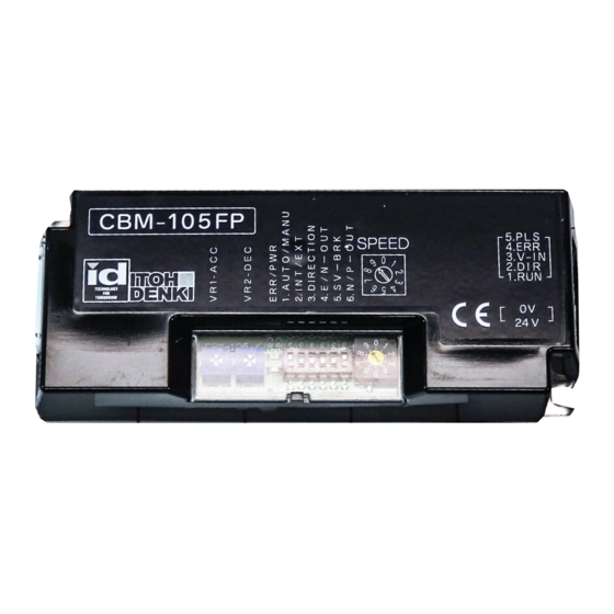
- Page 4 2. C IRCUIT BOARD PRESENTATION ENERAL DESCRIPTION • Fastener hardware - 2 spring washers M4 - 2 nuts M4 • 1 Connector WAGO 734-102 (2 points) • 1 Connector WAGO 733-105 (5 points) 1 Power Moller ® 24 brushless = 1 CBM-105 IMENSIONS CBM-105FP1-EU1 ECHNICAL...
- Page 5 PECIFICATIONS Protection 7A Input current without motorized roller 0.03A Input power without motorized roller 1,5W Motor start time after start signal IP20 Integrated fuse of 7A Protection Thermal protection (95°C for circuit board and 105°C for the motor) Initialisation time From 0 to 40 °C Motorized roller start and stop Direction of rotation...
- Page 6 3. T ECHNICAL DATAS ACCORDING MOTORIZED ROLLER PM500FE HARACTERISTICS WITH MOTORIZED ROLLER PM500FE Speed code 15 Tangential force Current (A) No load Nominal Nominal Nominal No load Nominal tension 17,4 13,7 133,9 15,9 13,7 133,9 15,2 13,7 133,9 14,5 13,7 133,9 13,7 13,7...
- Page 7 PM500FE Speed code 25 Tangential force Current (A) No load Nominal Nominal Nominal No load Nominal tension 29,3 25,4 26,8 25,4 25,6 25,3 24,4 24,4 23,1 23,1 21,9 21,9 19,5 19,5 18,3 18,3 17,0 17,0 15,9 15,9 14,6 14,6 13,4 13,4 12,2 12,2...
- Page 8 PM500FE Speed code 55 Tangential force Current (A) No load Nominal Nominal Nominal No load Nominal tension 61,7 47,3 42,8 56,6 47,3 42,8 54,0 47,3 42,8 51,4 47,3 42,8 48,9 47,3 42,8 46,3 46,3 42,9 41,1 41,1 43,4 38,6 38,6 43,4 36,0 36,0...
- Page 9 PM500FE Speed code 90 Tangential force Current (A) No load Nominal Nominal Nominal No load Nominal tension 104,1 90,2 24,9 95,4 90,2 24,9 91,0 90,2 24,9 86,7 86,7 25,0 82,4 82,4 25,2 78,0 78,0 25,4 69,3 69,3 25,7 65,0 65,0 25,8 60,7 60,7...
- Page 10 PM605FE HARACTERISTICS WITH MOTORIZED ROLLER PM605FE Speed code 15 Tangential force Current (A) No load Nominal Nominal Nominal No load Nominal tension 21,1 16,6 110,7 19,2 16,6 110,7 18,4 16,6 110,7 17,5 16,6 110,7 16,6 16,6 110,7 15,7 15,7 110,9 14,0 14,0 112,2...
- Page 11 PM605FE Speed code 25 Tangential force Current (A) No load Nominal Nominal Nominal No load Nominal tension 35,5 30,7 64,5 32,4 30,7 64,5 31,0 30,6 64,5 29,5 29,5 64,5 28,0 28,0 64,5 26,5 26,6 66,1 23,6 23,6 66,1 22,1 22,1 66,1 20,6 20,6...
- Page 12 PM605FE Speed code 55 Tangential force Current (A) No load Nominal Nominal Nominal No load Nominal tension 74,7 57,2 35,4 68,5 57,2 35,4 65,3 57,2 35,4 62,2 57,2 35,4 59,2 57,2 35,4 56,0 56,0 35,5 49,7 49,7 35,9 46,7 46,7 35,9 43,6 43,6...
- Page 13 PM605FE Speed code 90 Tangential force Current (A) No load Nominal Nominal Nominal No load Nominal tension 126,0 109,1 19,6 115,4 109,1 19,6 110,1 109,1 19,6 104,9 104,9 19,6 99,7 99,7 21,8 94,4 94,4 21,8 83,9 83,9 21,8 78,7 78,7 21,8 73,4 73,4...
- Page 14 PM500FP HARACTERISTICS WITH MOTORIZED ROLLER PM500FP Speed code 15 Tangential force Current (A) No load Nominal Nominal Nominal No load Nominal tension 17,7 14,6 158,1 16,3 14,6 158,1 15,5 14,6 158,1 14,8 14,6 158,1 14,1 14,1 158,8 13,3 13,3 159,5 11,8 11,8 160,8...
- Page 15 PM500FP Speed code 55 Tangential force Current (A) No load Nominal Nominal Nominal No load Nominal tension 67,0 55,0 47,6 61,4 55,0 47,6 58,6 55,0 47,6 55,8 55,0 47,6 53,1 53,1 47,8 50,3 50,3 48,0 44,7 44,7 48,4 41,9 41,9 48,6 39,1 39,1...
- Page 16 4. L OCATION OF ITEMS LED2 Red LED error Potentiometer for acceleration Potentiometer for deceleration 5. W IRING NTERNAL CIRCUIT DIAGRAM 3.3K nRUN IN +24V 3.3K nDIR IN Vinput PNP ERR OUT PULSE NPN ERR OUT CBM-105FP1-EU1 ECHNICAL OCUMENTATION CBM-105FN1-EU1 Original notice - T1.3...
- Page 17 CN1 - P 24VDC ONNECTOR OWER SUPPLY 0 VDC 24 VDC CN2 - T 1 - S ONNECTOR ERMINAL TART ▶ ▶ Motor pulse signal output Motor pulse signal output ▶ ▶ Error signal output Error signal output ◀ ◀ ◀...
- Page 18 CN2 - T 2 (D ONNECTOR ERMINAL IRECTION OF ROTATION • Input current 7,3 mA at 24 VDC ◀ Terminal 2 of CN2. roller will slow down then stop for 0.5s before starting to accelerate in the opposite direction of rotation. ON Command CN2 - Terminal 1 Change direction command...
- Page 19 CN2 - T 4 - E (ERR) ONNECTOR ERMINAL RROR SIGNAL function of the programmable logic controller using a resistor (not ▶ Error signal output a fault. When powering off and on, the error signal is sent. Do not consider this signal during 0.5s to power on, and 2s to power off. 24-2,5 0,025 CBM-105FP1-EU1...
- Page 20 CN2 - T 5 - P (PLS) ONNECTOR ERMINAL ULSE SIGNAL Selectors Number of External via a ▶ Frequency rotor turns Pulse signal output voltage SW1-1 (rpm) 4638 4556 4349 4141 3934 3727 3313 3106 2899 2692 2485 2278 damaging the transistor. 2071 •...
- Page 21 6. LED 1 LED 2 LED 1 (green) The indicator is lit when the control panel is powered. LED 2 (red) The indicator is lit when a malfunction has occurred and allows 7. P OTENTIOMETERS VR1 - Acceleration VR2 - Deceleration •...
- Page 22 8. D SWITCH FOR CONFIGURATION SW1 factory setting Dip-switch Fonction (see technical data in function of the motorized roller). Low speed range (0 – 10 V). (Manual setting) selection Change of CW or CCW rotation direction in function of the state of Termi- nal 2 of CN2 (see chapter on the rotation direction).
- Page 23 SW1 - D 2 : S SWITCH ELECTION INTERNAL EXTERNAL SPEED Must connect 0V of the circuit board with Range of high speed Range of low speed Exemple : PM500FE serie - Speed code 55 Dip-switch SW1 Speed 36,0 28,3 CBM-105FP1-EU1 ECHNICAL OCUMENTATION...
- Page 24 SW1 - D 3 : S SWITCH ELECTION OF DIRECTION OF ROTATION ◀ of the rotation direction selection associated with dip-switch 3 and the series of the motorized roller. PM500FE (50E) - PM605FE (60E) series PM500FS (50) - PM500FP (50P) series CBM-105FP1-EU1 ECHNICAL OCUMENTATION...
- Page 25 SW1 - D 4 : E SWITCH RROR SIGNAL Error signal there is a fault. LED 1 Led off Led on LED 2 then LED off during Led off Led on 1,5 s then repeating the CBM-105FP1-EU1 ECHNICAL OCUMENTATION CBM-105FN1-EU1 Original notice - T1.3...
- Page 26 Error signal input Motorized SW1-4 SW1-4 Cause / Motorized roller roller Signal reset symptom restart condition No signal n.a. sending No signal No signal No power Circuit board No signal sending damaged board. signal and restarts the motorized roller at the same time. 1 minute after drops below the thermal trip Thermister error No signal...
- Page 27 SW1 - D 5 : E SWITCH NABLE DISABLE ERVO BRAKE Servo-brake enabled • Maintain motorized roller position when stopped • Return motorized roller to its stop position when it motorized roller range is indicated in the “technical data as a Servo-brake disabled force.
- Page 28 EC Machinery Directive 2006/42/EC, Annex II B The manufacturer : Distributed in Europe by: hereby declares that the product series: CBM-105 IRCUIT OARD authorities). ITOH DENKI CO., L 1146-2 A 679-0105 J SAZUMA ASAI YOGO APAN EC Directives applied :...
- Page 29 ITOH DENKI EUROPE S.A.S. ITOH DENKI BRANCH ITOH DENKI BRANCH UNITED KINGDOM GERMANY Postfach 10 05 43 P.A.E. les Jourdies E-mail : info@itoh-denki.de E-mail : info@itoh-denki.com E-mail : info@itoh-denki.com WWW.ITOH-DENKI.COM...
Need help?
Do you have a question about the Power Moller CBM-105FP1-EU1 and is the answer not in the manual?
Questions and answers