Table of Contents
Advertisement
Quick Links
ISSUE 1A-10-2015
PRONAR Sp. z o.o.
17-210 NAREW, UL. MICKIEWICZA 101A, WOJ. PODLASKIE, POLAND
Phone.:
Fax:
OPERATOR'S MANUAL
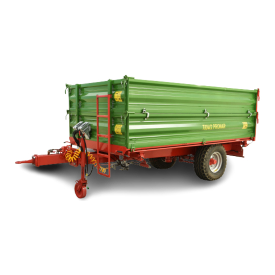
PRONAR T654/2
TRANSLATION OF THE ORIGINAL DOCUMENT
+48 085 681 63 29
+48 085 681 63 81
+48 085 681 63 83
TRAILER
PUBLICATION NO. 487N-00000000-UM
+48 085 681 64 29
+48 085 681 63 82
+48 085 682 71 10
www.pronar.pl
EN
Advertisement
Table of Contents

Related Manuals for PRONAR T654/2


Summary of Contents for PRONAR T654/2
- Page 1 PRONAR Sp. z o.o. 17-210 NAREW, UL. MICKIEWICZA 101A, WOJ. PODLASKIE, POLAND Phone.: +48 085 681 63 29 +48 085 681 64 29 +48 085 681 63 81 +48 085 681 63 82 Fax: +48 085 681 63 83 +48 085 682 71 10 www.pronar.pl...
- Page 3 Thank you for purchasing our trailer. In the interests of your safety and care for the reliability and durability of the machine, we ask that you familiarise yourself with the content of this manual. Remember!!! Before using the trailer for the first time, check if the wheels are properly tightened!!! Regularly check the technical condition of the machine in accordance with the attached schedule.
- Page 5 The machine is designed to meet obligatory standards, documents and legal regulations currently in force. The manual describes the basic safety and operation rules of Pronar T654/2 trailer. If the information contained in the Operator's Manual needs clarification, the user should refer for assistance to the sale point where the machine was purchased or to the manufacturer.
- Page 6 SYMBOLS USED IN THIS MANUAL Information, descriptions of danger, precautions, recommendations and orders associated with user safety instructions are indicated as follows: and preceded by the word "DANGER". Failure to observe the instructions may endanger the machine operator's or other person's health or life. Particularly important information and instructions, the observance of which is essential, are indicated with the sign: and preceded by the word "ATTENTION".
- Page 7 DETERMINING THE DIRECTIONS FOR THE MANUAL'S NEEDS Left side — a left hand side of the person facing the machine's forward travel direction. Right side — a right hand side of the person facing the machine's forward travel direction. SCOPE OF OPERATION STEPS Operation steps are indicated with the following sign: The result of an operation/adjustment task or any notes on execution of the tasks performed is indicated with the sign...
-
Page 9: Table Of Contents
TABLE OF CONTENTS BASIC INFORMATION 1.1 IDENTIFICATION 1.1.1 TRAILER IDENTIFICATION 1.1.2 AXLE IDENTIFICATION 1.1.3 LIST OF FACTORY NUMBERS 1.2 PROPER USE 1.3 EQUIPMENT 1.4 TERMS & CONDITIONS OF WARRANTY 1.5 TRANSPORT 1.10 1.5.1 TRANSPORT ON VEHICLE. 1.11 1.5.2 INDEPENDENT TRANSPORT BY THE USER. 1.13 1.6 ENVIRONMENTAL HAZARDS 1.13... - Page 10 DESIGN AND OPERATION 3.1 TECHNICAL SPECIFICATION 3.2 TRAILER CONSTRUCTION 3.2.1 CHASSIS 3.2.2 LOAD BOX 3.2.3 MAIN BRAKE 3.2.4 HYDRAULIC TIPPING SYSTEM 3.14 3.2.5 PARKING BRAKE 3.16 3.2.6 LIGHTING SYSTEM 3.17 CORRECT USE 4.1 PREPARING FOR WORK BEFORE THE FIRST USE 4.1.1 CHECKING THE TRAILER AFTER DELIVERY 4.1.2...
- Page 11 5.2.4 MOUNTING AND DISMOUNTING WHEEL, INSPECTION OF WHEEL NUT TIGHTENING 5.2.5 CHECKING AIR PRESSURE IN TYRES, EVALUATING TECHNICAL CONDITION OF TYRES AND STEEL WHEELS 5.2.6 CHECKING THICKNESS OF BRAKE SHOE LININGS 5.10 5.2.7 ADJUSTMENT OF MECHANICAL BRAKES 5.11 5.2.8 REPLACEMENT OF OVERRUN BRAKE CABLE AND ADJUSTMENT OF CABLE TENSION.
- Page 12 5.7.1 HYDRAULIC OIL 5.34 5.7.2 LUBRICANTS 5.35 5.8 CLEANING THE TRAILER 5.35 5.9 STORAGE 5.37 5.10 TIGHTENING TORQUE FOR NUT AND BOLT CONNECTIONS 5.38 5.11 INSTALLATION AND DISASSEMBLY OF WALL EXTENSIONS 5.39 5.12 TROUBLESHOOTING 5.40...
- Page 13 SECTION BASIC INFORMATION...
-
Page 14: Identification
PRONAR T654/2 SECTION 1 1.1 IDENTIFICATION 1.1.1 TRAILER IDENTIFICATION FIGURE 1.1 Location of the data plate and serial number (1) data plate, (2) serial number The trailer is marked with the data plate (1), and the factory number (2) located on a gold painted rectangle. -
Page 15: Axle Identification
SECTION 1 PRONAR T654/2 TABLE 1.1 Markings on data plate ITEM MARKING General description and purpose Symbol / type of trailer Year of manufacture Seventeen digit vehicle identification number (VIN) Official certificate number Tare weight Maximum gross weight Carrying capacity... -
Page 16: List Of Factory Numbers
PRONAR T654/2 SECTION 1 1.1.3 LIST OF FACTORY NUMBERS AXLE FACTORY NUMBER In the event of ordering a replacement part or in the case of the appearance of problems it is often essential to give the factory numbers of parts or the VIN number of the trailer, therefore it is recommended that these numbers are inscribed in the spaces above. - Page 17 SECTION 1 PRONAR T654/2 ATTENTION The trailer must not be used for purposes other than those for which it is intended. The user MUST NOT: • transport people, animals, hazardous materials, chemically aggressive loads that will corrode the construction elements of the trailer (causing corrosion of steel, destruction of paint coat, dissolving plastic elements and destruction of rubber elements etc.),...
- Page 18 PRONAR T654/2 SECTION 1 The trailer may only be used by persons, who: • are familiar with the contents of this publication and with the contents of the agricultural tractor Operator's Manual, • have been trained in trailer operation and safe operation, •...
- Page 19 SECTION 1 PRONAR T654/2 CONTENTS UNIT REQUIREMENTS Other requirements Min. tractor power kW / 24.7 / 33.6 Horsepower (1) – use of other oil is permitted, on condition that it may be mixed with the oil in the trailer. Detailed information can be found on the product information card.
-
Page 20: Equipment
PRONAR T654/2 SECTION 1 CONTENTS UNIT REQUIREMENTS Trailer's drawbar Diameter of drawbar eye (1) – use of other oil is permitted, on condition that it may be mixed with the oil in the trailer. Detailed information can be found on the product information card. -
Page 21: Terms & Conditions Of Warranty
Information concerning tires is provided at the end of this publication in ANNEX A. 1.4 TERMS & CONDITIONS OF WARRANTY PRONAR Sp. z o.o. Narew guarantees the reliable operation of the machine when it is used according to its intended purpose as described in the OPERATOR'S MANUAL. The repair period is specified in the WARRANTY BOOK. -
Page 22: Transport
PRONAR T654/2 SECTION 1 • bearings. The warranty service only applies to such cases as: mechanical damage which is not the user's fault, factory defects of parts, etc. In the event of damage arising from: • mechanical damage which is the user's fault, road accidents, •... -
Page 23: Transport On Vehicle
SECTION 1 PRONAR T654/2 1.5.1 TRANSPORT ON VEHICLE. Loading and unloading of trailer from vehicle shall be conducted using loading ramp with the aid of an agricultural tractor. During work, adhere to the general principles of occupational health and safety (OHS) applicable to reloading work. Persons operating reloading equipment must have the qualifications required to operate these machines. - Page 24 PRONAR T654/2 SECTION 1 elements must be selected according to the guidelines of the Manufacturer of these elements. FIGURE 1.3 Positioning of transport lugs (1) transport lug, (2) longitudinal member of upper frame, (3) longitudinal member of lower frame In case of doubt apply a greater number of securing straps in order to immobilise the trailer. If necessary, sharp edges of trailer should be protected at the same time protecting the securing straps from breaking during transport.
-
Page 25: Independent Transport By The User
SECTION 1 PRONAR T654/2 DANGER Incorrect use of securing measures may cause an accident. 1.5.2 INDEPENDENT TRANSPORT BY THE USER. ATTENTION Before transporting independently, the tractor driver must carefully read this Operator's Manual and observe its recommendations. In the event of independent transport by the user after purchase of the trailer, the user must read the trailer Operator's Manual and adhere to the recommendations contained therein. -
Page 26: Withdrawal From Use
PRONAR T654/2 SECTION 1 DANGER Used hydraulic oil or gathered remains mixed with absorbent material should be stored in a precisely marked container. Do not use food packaging for this purpose. The hydraulic system of the trailer is filled with L-HL32 Lotos hydraulic oil. - Page 27 SECTION 1 PRONAR T654/2 DANGER Avoid contact of skin with oil. Do not allow used hydraulic oil to spill. 1.15...
- Page 28 PRONAR T654/2 SECTION 1 1.16...
-
Page 29: Safety Advice
SECTION SAFETY ADVICE... -
Page 30: Basic Safety Rules
PRONAR T654/2 SECTION 2 2.1 BASIC SAFETY RULES 2.1.1 USE OF TRAILER • Before using the trailer, the user must carefully read this Operator's Manual and the WARRANTY BOOK. When operating the machine, the operator must comply with all recommendations contained in the Operator's Manual. -
Page 31: Hitching And Disconnecting From Tractor
SECTION 2 PRONAR T654/2 • The user is obliged to acquaint himself with the construction, action and the principles of safe usage of the trailer. 2.1.2 HITCHING AND DISCONNECTING FROM TRACTOR • Do NOT hitch the trailer to tractor if the tractor does not fulfil the requirements specified by the Manufacturer (minimum tractor power demand, wrong hitch, etc.) -
Page 32: Hydraulic And Pneumatic Systems
PRONAR T654/2 SECTION 2 • Before hitching the trailer check that both machines are in good technical condition. • Be especially careful when hitching the machine. • When hitching, there must be nobody between the trailers. Person assisting in hitching the machines should stand outside the area of danger and be visible to the tractor driver at all times. -
Page 33: Loading And Unloading
SECTION 2 PRONAR T654/2 • After changing the hydraulic oil, the used oil should be properly disposed of. Used oil or oil which has lost its properties should be stored in original containers or replacement containers resistant to action of hydrocarbons. Replacement containers must be clearly marked and appropriately stored. - Page 34 PRONAR T654/2 SECTION 2 • During loading and unloading the trailer the drawbar eye and the tractor hitch are subjected to great vertical loading. • Before raising load box the tipping pins should be placed on the intended unloading side. Check if the pins are correctly inserted and secured.
-
Page 35: Transporting The Machine
SECTION 2 PRONAR T654/2 • After completed unloading, ensure that the load box is empty. • Do NOT drive with the load box raised. • When closing or opening the rear grain chute gate or the walls and extensions take particular care to avoid crushing fingers. - Page 36 PRONAR T654/2 SECTION 2 • Adjust speed to road conditions. • Chocks (1) should be placed only under one wheel (one chock in front of the wheel, the other behind the wheel - figure (2.1)). • The machine must NOT be left unsecured. When not connected to the tractor, the...
- Page 37 SECTION 2 PRONAR T654/2 • Periodically drain water from the air tanks in pneumatic system. During frosts, freezing water may cause damage to pneumatic system components. • Reckless driving and excessive speed may cause accidents. • A load protruding beyond the outline of the trailer should be marked according to the road traffic regulations.
-
Page 38: Tyres
PRONAR T654/2 SECTION 2 the gross weight of the trailer, exceeding the weight limit causes drastic reduction of basic braking effectiveness. • Prolonged driving across steep ground may lead to loss of braking efficiency. • If the trailer is the last vehicle in the group, - figure (2.2), a slow-moving vehicle warning sign should be placed on the trailer's rear load box wall. -
Page 39: Maintenance
SECTION 2 PRONAR T654/2 could raise tyre pressure by as much as 1 bar. At high temperatures and pressure, reduce load or speed. Do not release air from warm tyres to adjust the pressure or the tyres will be underinflated when temperatures return to normal. - Page 40 PRONAR T654/2 SECTION 2 immediately cleaned and disinfected. In the event of more serious injuries, seek a doctor's advice. • Repair, maintenance and cleaning work should be carried out with the tractor's engine switched off and the ignition key removed. Tractor and trailer should be immobilized with parking brake and chocks should be placed under the trailer wheels.
-
Page 41: Description Of Minimal Risk
2.2 DESCRIPTION OF MINIMAL RISK Pronar Sp. z o. o. in Narew has made every effort to eliminate the risk of accidents. There is, however, a certain residual risk, which could lead to an accident, and this is connected mainly with the actions described below: •... -
Page 42: Information And Warning Decals
In the event of their destruction, they must be replaced with new ones. Safety decals are available from your PRONAR dealer or directly from PRONAR customer service. New assemblies, changed during repair, must be labelled once again with the appropriate safety signs. - Page 43 SECTION 2 PRONAR T654/2 TABLE 2.1 Information and warning decals ITEM DECAL MEANING Trailer version. 487N-00000001 Caution! Before starting work, carefully read the Operator's Manual. 70N-00000004 Before beginning servicing or repairs, turn off tractor engine and remove key from ignition Ensure that...
- Page 44 PRONAR T654/2 SECTION 2 ITEM DECAL MEANING Caution! Danger of electric shock. Keep a safe distance from overhead electric power lines during unloading. 58N-0000020 Danger of crushing Do NOT perform any maintenance or repairs on the load box that is loaded, raised or not supported.
- Page 45 SECTION 2 PRONAR T654/2 ITEM DECAL MEANING Conduit supplying hydraulic tipping system. 29N-0000027 Air pressure in the tyres. Manufacturer's website. 62N-0000014 (1) – pressure value should be adapted to tyres Numbers in the item column correspond to labels in figure (2.3) Decals –...
- Page 46 PRONAR T654/2 SECTION 2 FIGURE 2.3 Locations of information and warning decals. 2.18...
-
Page 47: Design And Operation
SECTION DESIGN AND OPERATION... -
Page 48: Technical Specification
PRONAR T654/2 SECTION 3 3.1 TECHNICAL SPECIFICATION TABLE 3.1 Basic technical date of the standard trailer version CONTENTS UNIT Trailer dimensions Total length 4,960 Total width 1,990 Total height 1,430 Internal load box dimensions Length 3,500 Width 1,820 Height Weight and carrying capacity... -
Page 49: Trailer Construction
SECTION 3 PRONAR T654/2 3.2 TRAILER CONSTRUCTION 3.2.1 CHASSIS Trailer chassis consists of subassemblies indicated in figure (3.1). Lower frame (1) is a structure welded from steel sections. Lower frame design depends on configuration of a given trailer version. Individual trailer versions have different drawbars – figure (3.2). The main load-bearing elements of the lower frame (1) are two longitudinal members connected with each other by means of crossbars. - Page 50 PRONAR T654/2 SECTION 3 FIGURE 3.1 Trailer chassis (1) lower frame, (2) tipping cylinder socket, (3) lights support beam, (4) axle, (5) drawbar, (6) drawbar hitching eye, (7) rear beam, (8) front crossbar, (9) hitch, (10) load box support, (11) trailer support, (12) conduit bracket, (13) fender...
- Page 51 SECTION 3 PRONAR T654/2 FIGURE 3.2 Trailer chassis (1) lower frame, (2) drawbar for connecting with upper transport hitch (3) drawbar for connecting with lower transport hitch, (4) overrun drawbar...
-
Page 52: Load Box
PRONAR T654/2 SECTION 3 3.2.2 LOAD BOX The trailer's load box consists of: upper frame (1) – figure (3.3) with welded steel floor, side walls (3) front wall (3) and rear wall (4). Side walls and rear wall can be opened in order to load/unload materials. - Page 53 SECTION 3 PRONAR T654/2 FIGURE 3.3 Load box – rear view (1) upper frame, (2) side wall, (3) front wall, (4) rear wall, (5) rear stake of walls, (6) lever, (7) rear stake of wall extensions, (8) hinge pin, (9) front wall extension, (10) side wall...
- Page 54 PRONAR T654/2 SECTION 3 FIGURE 3.4 Load box (1) front wall closing lever, (2) ladder, (3) wheel chocks, (4) left lock In order to enable very precise unloading of loose materials there is a slide opening placed in the rear wall (1) – figure (3.5), which is raised using lever (2). When in upper position and also during transport the slide must be secured by tightening the locking screw (3).
-
Page 55: Main Brake
SECTION 3 PRONAR T654/2 FIGURE 3.5 Rear wall slide gate with lock and chute (1) slide gate, (2) lever, (3) locking screw, (4) chute 3.2.3 MAIN BRAKE The trailer is equipped with one of four types of main brake: • double conduit pneumatic brake system with three position regulator, figure (3.6), •... - Page 56 PRONAR T654/2 SECTION 3 compressed air conduit is connected to the tractor, the device automatically applying the brakes now changes its position to allow normal brake operation. FIGURE 3.6 Design and diagram of the double conduit pneumatic brake system. (1) air tank, (2) control valve, (3) braking force regulator, (4) pneumatic cylinder, (5) conduit...
- Page 57 SECTION 3 PRONAR T654/2 FIGURE 3.7 Design and diagram of the single conduit pneumatic brake system (1) air tank, (2) control valve, (3) braking force regulator, (4) pneumatic cylinder, (5) conduit connection (black), (6) air filter, (7) air tank control connector, (8) pneumatic cylinder control connector, (9) drain valve 3.11...
- Page 58 PRONAR T654/2 SECTION 3 FIGURE 3.8 Design and diagram of hydraulic braking system (1) hydraulic cylinder, (2) hydraulic quick-coupler, (3) information decal The main hydraulic brake (available as optional equipment) is activated from the tractor driver's cab by depressing the brake pedal. Agricultural tractor equipped with suitable hydraulic system is required to operate the hydraulic braking system.
- Page 59 SECTION 3 PRONAR T654/2 FIGURE 3.9 Overrun brake (1) overrun drawbar, (2) wheel axle with overrun brake, (3) handbrake lever, (4) steel cable, (5) guide roller Overrun brake system design is shown in figure (3.9). As standard, drawbar (1) with movable hitching eye is secured to the faceplate of the lower frame.
-
Page 60: Hydraulic Tipping System
PRONAR T654/2 SECTION 3 the lever (4) prior to moving off. Three working positions are available: A - "no load”, B - "half load” and C - "full load”. FIGURE 3.10 Control valve and braking force regulator (1) control valve, (2) braking force regulator, (3) trailer parking brake release button, (4) work selection regulator lever, (A) position "NO LOAD”, (B) position "HALF LOAD”, (C) position... - Page 61 SECTION 3 PRONAR T654/2 FIGURE 3.11 Hydraulic tipping system design and diagram (1) telescopic cylinder, (2) cut-off valve, (3) quick coupler, (4) control cable, (5) guide roller, (6) information decal ATTENTION Cut-off valve (2) – figure (3.11) limits the tipping angle of the load box when tipped to the sides and to the rear.
-
Page 62: Parking Brake
PRONAR T654/2 SECTION 3 3.2.5 PARKING BRAKE FIGURE 3.12 Parking brake design (1) crank mechanism, (2) parking brake lever in overrun drawbar, (3) cable, (4) guide roller, (5) securing button The parking brake is used to immobilise and prevent the trailer from moving while standing motionless. -
Page 63: Lighting System
SECTION 3 PRONAR T654/2 In all versions of the brake, steel cable (3), guided by the roller (4), is connected with the expander arms and brake crank or lever mechanism. Tightening the cable causes tilting of the expander levers, which part the jaws of the brake shoes immobilising the trailer. - Page 64 PRONAR T654/2 SECTION 3 FIGURE 3.13 Electrical system concept diagram Marking according to table (3.2) The trailer electrical system is designed for supply from direct current source of 12 V. Connection of the trailer electrical system with the tractor should be made through an appropriate connection lead delivered with the new trailer.
- Page 65 SECTION 3 PRONAR T654/2 FIGURE 3.14 Arrangement of lighting system components – rear view (1) rear left lamp assembly, (2) rear right lamp assembly, (3) license plate light, (4) rear 7-pin socket TABLE 3.3 Marking of connections of X7P and GT sockets...
- Page 66 PRONAR T654/2 SECTION 3 FIGURE 3.15 Arrangement of lighting system components – front view (1) front parking light, (2) front 7-pin socket 3.20...
-
Page 67: Correct Use
SECTION CORRECT USE... -
Page 68: Preparing For Work Before The First Use
PRONAR T654/2 SECTION 4 4.1 PREPARING FOR WORK BEFORE THE FIRST 4.1.1 CHECKING THE TRAILER AFTER DELIVERY The manufacturer guarantees that the trailer is fully operational and has been checked according to quality control procedures and is ready for normal use. This does not release the user from an obligation to check the machine's condition after delivery and before first use. -
Page 69: Preparing The Trailer For First Hitching To Tractor
SECTION 4 PRONAR T654/2 4.1.2 PREPARING THE TRAILER FOR FIRST HITCHING TO TRACTOR Preparation Check all the trailer's lubrication points, lubricate the machine as needed according to recommendations provided in section 5, Check if the nuts and bolts fixing the wheels are properly tightened. -
Page 70: Hitching And Unhitching The Trailer From Tractor
PRONAR T654/2 SECTION 4 When moving off check if the main brakes operate correctly. Perform test drive. The trailer may be hitched only when all preparatory activities including inspection of technical condition have been completed satisfactorily. If during test run worrying symptoms occur such as: •... - Page 71 SECTION 4 PRONAR T654/2 In order to hitch the trailer to the tractor, perform the actions below in the sequence presented. Machine must be immobilised by parking brake. Hitching to tractor Immobilise trailer with parking brake. Pull brake mechanism clockwise until resistance is felt – if trailer is equipped with standard parking brake.
- Page 72 PRONAR T654/2 SECTION 4 FIGURE 4.1 Trailer support (1) straight support with wheel, (2) cylinder, (3), (4) conduits, (5), (6) information decals Connect pneumatic system conduits (applies to single conduit pneumatic system): Connect pneumatic conduit marked black with black socket in tractor.
- Page 73 SECTION 4 PRONAR T654/2 Connect main lead supplying electrical lighting system. Turning crank (2) – figure (4.1) raise support wheel. Press support pedal (4) and holding wheel with hand (3) place it in transport position. DANGER When hitching, there must be nobody between the trailer and the tractor. When hitching the machine, tractor driver must exercise caution and make sure that nobody is present in the hazard zone.
- Page 74 PRONAR T654/2 SECTION 4 Unhitching the trailer In order to unhitch the trailer from the tractor follow these steps. Immobilise tractor and trailer with parking brake. Turn off tractor engine. Ensure that unauthorised persons do not have access to the tractor cab.
-
Page 75: Hitching And Unhitching The Second Trailer
SECTION 4 PRONAR T654/2 DANGER Exercise caution when unhitching the trailer from the tractor. Ensure good visibility. Unless it is necessary, do not go between tractor and trailer. Before disconnecting conduits and drawbar eye, close tractor cab and secure it against access by unauthorised persons. - Page 76 PRONAR T654/2 SECTION 4 FIGURE 4.2 Rear hitch (1) hitch body, (2) hitch pin, (3) chain with linchpin securing pin Unhitching the second trailer Immobilise tractor and trailers with parking brake. Turn off tractor engine. Ensure that unauthorised persons do not have access to the tractor cab.
-
Page 77: Loading And Securing Load
SECTION 4 PRONAR T654/2 ATTENTION Do NOT hitch a second trailer constructed on any chassis except dual axle chassis. The rear manual hitch is designed only for towing a second trailer whose permissible gross weight does not exceed 6 100 kg. - Page 78 PRONAR T654/2 SECTION 4 Due to various densities of materials, the use of the total load box capacity may lead to exceeding permissible carrying capacity of the trailer. Guideline specific weight of selected materials is shown in table (4.1). Take care not to overload the machine. Loading should be carried out by a person experienced in this type of work and having appropriate authorisation for operating equipment (if required).
- Page 79 SECTION 4 PRONAR T654/2 WEIGHT BY VOLUME TYPE OF MATERIAL KG/M solid bricks 1,500 – 2,100 hollow bricks 1,000 – 1,200 stones 1,500 – 2,200 soft wood 300 - 450 hard sawn timber 500 - 600 impregnated timber 600 - 800 steel structures 700 –...
- Page 80 PRONAR T654/2 SECTION 4 WEIGHT BY VOLUME TYPE OF MATERIAL KG/M cut cereal mass in bulk trailer 35 - 75 cut cereal mass in gathering trailer 60 - 100 green fodder in swath 28 - 35 cut green fodder in bulk trailer...
- Page 81 SECTION 4 PRONAR T654/2 WEIGHT BY VOLUME TYPE OF MATERIAL KG/M grass 360 - 500 maize 700 - 850 wheat 720 - 830 oil seed rape 600 - 750 linseed 640 - 750 lupins 700 - 800 oats 400 - 530...
- Page 82 PRONAR T654/2 SECTION 4 Loose bulk material Loading bulk materials is normally conducted with the use of loaders or conveyors and possibly loading manually. On completion of loading, the load should be evenly spread over the whole surface of the load box.
- Page 83 SECTION 4 PRONAR T654/2 materials and artificial fertilisers, which may be transported on agricultural trailers on the condition that they are transported in the appropriate packaging and in quantities envisaged by the ADR agreement. High volume loads High-volume loads (light with a high volume), such as hay, straw bales - rectangular or round, green fodder, etc., are recommended to be loaded with the aid of the appropriate mechanical...
-
Page 84: Transporting Loads
PRONAR T654/2 SECTION 4 etc.). During transport, packaging contents may not come into contact with load box. Therefore, ensure the appropriate tightness of containers. DANGER If there is a danger of load packaging moving, do NOT transport this type of material. - Page 85 SECTION 4 PRONAR T654/2 • The trailer must not be overloaded, loads must be uniformly distributed so that the maximum permissible trailer axle and hitch loads are not exceeded. The trailer's maximum carrying capacity must not be exceeded as this can damage the trailer and pose a risk to the operator or other road users.
-
Page 86: Unloading
PRONAR T654/2 SECTION 4 • Speed must be sufficiently reduced before making a turn or driving on an uneven road or a slope. • When driving, avoid sharp turns especially on slopes. • Please note that the braking distance of the tractor and trailer combination is substantially increased at higher speeds and loads. - Page 87 SECTION 4 PRONAR T654/2 tipping pins (1) and (2) – figure (4.3), (connecting load box to lower frame) should be placed and properly interlocked on the side, which will be used to unload; Pins and individual sockets are designed so it is impossible to place...
- Page 88 PRONAR T654/2 SECTION 4 open appropriate locks of walls and/or wall extensions or open the chute sliding gate in the rear wall (depending on the direction in which unloading should take place); during opening exercise caution, because the load may exert great...
- Page 89 SECTION 4 PRONAR T654/2 close and secure the walls and wall extensions or chute opening, before moving off make sure that tipping pins are in correct position, i.e. with the handle facing downward. ATTENTION It is not recommended to unload the load box by opening the walls downwards (when lower locks of the load box are locked).
- Page 90 PRONAR T654/2 SECTION 4 the slide as required and lock again using the bolt. When unloading through the chute do not open wall locks or wall extension locks and tipping of the load box must be done very slowly and without jerking. Raising the load box quickly will exert large pressure on the rear part of the load box due to displacement of the carried material and could compromise trailer's stability.
-
Page 91: Proper Use And Maintenance Of Tyres
SECTION 4 PRONAR T654/2 DANGER When closing the rear chute gate or the walls take particular care to avoid crushing fingers. Ensure that during unloading nobody is near tipped load box or load material pouring out. Tipping may only be performed when trailer is hitched to tractor. - Page 92 PRONAR T654/2 SECTION 4 • Protect tyre valves using suitable caps to avoid soiling. • Do not exceed the trailer's maximum design speed. • When the trailer is operated all day, stop working for a minimum of one hour in the afternoon.
-
Page 93: Maintenance
SECTION MAINTENANCE... -
Page 94: Preliminary Information
PRONAR T654/2 SECTION 5 5.1 PRELIMINARY INFORMATION When using the trailer, regular inspections of its technical condition are essential and the performance of maintenance procedures, which keep the machine in good technical condition. In connection with this the user of the trailer is obliged to perform all the maintenance and adjustment procedures defined by the Manufacturer. -
Page 95: Checking Wheel Axle Bearings For Slackness
SECTION 5 PRONAR T654/2 may be performed by specialist workshops. DANGER Do NOT use the trailer when brake system is unreliable. 5.2.2 CHECKING WHEEL AXLE BEARINGS FOR SLACKNESS FIGURE 5.1 Lifting jack support point (1) wheel axle, (2) bolt, (3) lower frame Preparation procedures Hitch trailer to tractor, immobilize tractor with parking brake. - Page 96 PRONAR T654/2 SECTION 5 Raise the wheel (opposite to the side where chocks are placed). The lifting jack should be placed between bolts (2) - figure (5.1) securing axle (1) to lower frame (3). Recommended support points are marked with arrows. Lifting jack must be suitable for the weight of trailer.
-
Page 97: Adjustment Of Slackness Of Wheel Axle Bearings
SECTION 5 PRONAR T654/2 DANGER Before commencing work the user must read the instructions for lifting jack and adhere to the manufacturer's instructions. The lifting jack must be stably supported on the ground and so must the axle. Ensure that trailer shall not move during inspection of axle bearing slackness. -
Page 98: Mounting And Dismounting Wheel, Inspection Of Wheel Nut Tightening
PRONAR T654/2 SECTION 5 FIGURE 5.2 Adjustment of axle bearings (1) hub cover, (2) castellated nut, (3) cotter pin If the wheel is dismounted, bearing slackness is easy to check and adjust. 5.2.4 MOUNTING AND DISMOUNTING WHEEL, INSPECTION OF WHEEL NUT TIGHTENING Dismounting wheel Immobilise trailer with parking brake. - Page 99 SECTION 5 PRONAR T654/2 The lifting jack should have sufficient lifting capacity and should be technically reliable. The lifting jack must be positioned on a level and hard surface so as to prevent sinking into the ground or relocating the jack during lifting.
- Page 100 PRONAR T654/2 SECTION 5 FIGURE 5.3 Sequence of nut tightening (1) - (6) sequence of nut tightening, (L) spanner length, (F) user weight • After the first use of trailer (one-time inspection). • Every 2 – 3 hours of trailer travel (during the first month of trailer use).
-
Page 101: Checking Air Pressure In Tyres, Evaluating Technical Condition Of Tyres And Steel Wheels
SECTION 5 PRONAR T654/2 TABLE 5.1 Spanner arm WHEEL TIGHTENING TORQUE BODY WEIGHT (F) ARM LENGTH (L) [NM] [KG] 0.75 0.65 0.55 0.50 5.2.5 CHECKING AIR PRESSURE IN TYRES, EVALUATING TECHNICAL CONDITION OF TYRES AND STEEL WHEELS Air pressure in tyres should be checked each time after changing a spare wheel and at least once a month. -
Page 102: Checking Thickness Of Brake Shoe Linings
PRONAR T654/2 SECTION 5 Checking air pressure in tyres and visual inspection of steel wheels: • every 1 month of use, • if needed. 5.2.6 CHECKING THICKNESS OF BRAKE SHOE LININGS FIGURE 5.4 Checking brake shoe linings (1) brake drum, (2) disc, (3) inspection openings, (G) thickness of brake shoe lining During use of trailer, friction lining of brake drums is subject to wear. -
Page 103: Adjustment Of Mechanical Brakes
SECTION 5 PRONAR T654/2 Thickness of brake shoe linings should be checked every 6 months. Minimum thickness of brake shoe linings is 5mm. 5.2.7 ADJUSTMENT OF MECHANICAL BRAKES Considerable wear of brake shoe linings results in increased brake cylinder rod stroke and worse braking efficiency. - Page 104 PRONAR T654/2 SECTION 5 FIGURE 5.5 Design of wheel axle brake (1) expander arm , (2) expander shaft, (3) securing bolt, (4) brake cylinder, (5) cylinder piston rod, (6) cylinder fork, (7) fork pin, (8) equalising bar Adjustment must be made when: •...
- Page 105 SECTION 5 PRONAR T654/2 FIGURE 5.6 Principle of brake adjustment (1) expander arm, (2) expander shaft, (3) equalising bar, (4) cylinder fork Required maintenance activities Dismantle pin fixing the cylinder fork (4) with rudder bar (3). Mark position of expander arm (1) with regard to the shaft (2).
- Page 106 PRONAR T654/2 SECTION 5 Expander arm (1) should be moved by one notch in chosen direction. If the extent of cylinder action is still incorrect, move the lever again. After proper brake adjustment, at full braking, the expander arms should create the angle of 90° with the cylinder piston rod, and the stroke should amount to approximately half the length of the total stroke of the piston rod.
-
Page 107: Replacement Of Overrun Brake Cable And Adjustment Of Cable Tension
SECTION 5 PRONAR T654/2 5.2.8 REPLACEMENT OF OVERRUN BRAKE CABLE AND ADJUSTMENT OF CABLE TENSION. If trailer braking is considerably delayed in relation to tractor braking, check brake cable tension and check if position of expander arms is correctly adjusted - see section 5.2.8. -
Page 108: Replacement Of Parking Brake Cable And Adjustment Of Cable Tension
PRONAR T654/2 SECTION 5 Tighten overrun brake cable (3) using tensioner (1). Excessive brake cable tension can cause more rapid wear of brake linings and, in extreme cases, very sudden braking and trailer wheel blocking. Tighten nut (4), check brake action. - Page 109 SECTION 5 PRONAR T654/2 • after adjustment of axle brakes, • after repairs of axle brake system, • after repairs of parking brake system. FIGURE 5.8 Adjustment of main brakes (1) brake crank mechanism, (2) cable clamp nuts (3) hand brake cable, (4) guide roller Replacing the parking brake cable Hitch trailer to tractor.
- Page 110 PRONAR T654/2 SECTION 5 Loosen nuts of U-bolt clamps located at the ends of cable. Dismantle proper shackles at the ends of the cable. Dismantle parking brake cable. Clean parking brake components, lubricate crank mechanism and pins of cable guide rollers.
-
Page 111: Pneumatic System Maintenance
SECTION 5 PRONAR T654/2 Loosen nuts of U-bolt clamps on handbrake cable. Tighten cable and tighten clamps. Length of parking brake cable should be so selected that at total release of working and parking brake the cable would be loose and hanging by 1 - 2 cm. -
Page 112: Checking Air Tightness And Visual Inspection Of Pneumatic System
PRONAR T654/2 SECTION 5 • cleaning and maintaining pneumatic conduit connections, 5.3.2 CHECKING AIR TIGHTNESS AND VISUAL INSPECTION OF PNEUMATIC SYSTEM Checking air tightness of pneumatic systems Hitch trailer to tractor. Immobilise tractor and trailer with parking brake. Place chocks under trailer wheel. -
Page 113: Cleaning The Air Filters
SECTION 5 PRONAR T654/2 or repaired. If leaks appear at connections then tighten the connections. If air continues to escape, replace connection components or seals with new ones. Visual inspection of the system During tightness inspection attention should additionally be given to technical condition and degree of cleanness of the system components. -
Page 114: Draining Water From Air Tank
PRONAR T654/2 SECTION 5 Hold the filter cover (2) with the other hand. After removing slide lock, the cover is pushed off by the spring located in the filter housing. FIGURE 5.10 Air filter (1) securing slide lock, (2) air filter cover The filter element and the filter body should be carefully cleaned and blown through with compressed air. - Page 115 SECTION 5 PRONAR T654/2 The compressed air in the tank causes the removal of water to the exterior. FIGURE 5.11 Draining water from air tank (1) drain valve, (2) air tank Released valve stem should automatically close and stop flow of air from the tank.
-
Page 116: Cleaning The Drain Valve
PRONAR T654/2 SECTION 5 5.3.5 CLEANING THE DRAIN VALVE DANGER Release air from the air tank before dismantling drain valve. Required maintenance activities Completely reduce pressure in air tank. Reduction of pressure in tank is achieved by tilting the drain valve stem. -
Page 117: Replacement Of Pneumatic Conduit
SECTION 5 PRONAR T654/2 If the trailer is unhitched from the tractor, connections should be protected by covers and placed in their designated sockets. Before the winter period it is recommended to preserve the seal with special preparations (e.g. silicon grease for rubber elements). -
Page 118: Hydraulic System Maintenance
PRONAR T654/2 SECTION 5 TABLE 5.2 Tightening torques for pneumatic system fittings TIGHTENING PART NAME THREAD TORQUE (NM) M22x1.5 M14x1.5 Pneumatic system fittings M16x1.5 M18x1.5 M22x1.5 5.4 HYDRAULIC SYSTEM MAINTENANCE 5.4.1 PRELIMINARY INFORMATION Work connected with the repair, change or regeneration of hydraulic system components (tipping cylinder, valves etc.) should be entrusted to specialist establishments, having the... -
Page 119: Checking Technical Condition Of Hydraulic Connections And Sockets
SECTION 5 PRONAR T654/2 Clean connections and cylinders (tipping cylinder and possibly hydraulic brake system cylinder). Conduct test tipping of load box sideways and backwards. Press tractor brake pedal several times If trailer is equipped with hydraulic brake system (optional equipment). -
Page 120: Replacement Of Hydraulic Conduits
PRONAR T654/2 SECTION 5 5.4.4 REPLACEMENT OF HYDRAULIC CONDUITS Rubber hydraulic conduits must be replaced every 4 years regardless of their technical condition. This should be entrusted to specialised workshops. Replacement of hydraulic conduits: • every 4 years. 5.5 MAINTENANCE OF LIGHTING SYSTEM AND WARNING ELEMENTS 5.5.1 PRELIMINARY INFORMATION... -
Page 121: Trailer Lubrication
SECTION 5 PRONAR T654/2 Required maintenance activities Connect trailer to tractor with appropriate connection lead. Check if the connection lead is reliable. Check connection sockets in tractor and trailer. Clean and dry contaminated sockets. Check completeness and technical condition of trailer lights. - Page 122 PRONAR T654/2 SECTION 5 TABLE 5.4 Trailer lubrication schedule ITEM LUBRICATION POINT Hub bearing Drawbar eye Expander shaft sleeve in drum hub Overrun drawbar components Sockets of tipping cylinder and cylinder suspension Tipping cylinder ball bearing Parking brake mechanism Parking brake guide roller pins Articulated joints and sockets for installation of load box.
- Page 123 SECTION 5 PRONAR T654/2 ITEM LUBRICATION POINT Side wall locking lever Lubrication periods – M months, D – days TABLE 5.5 Recommended lubricants MARKING ACCORDING DESCRIPTION TO TAB. (5.4) machine general-purpose grease (lithium, calcium grease), permanent grease for heavily loaded elements with addition of MOS...
- Page 124 PRONAR T654/2 SECTION 5 FIGURE 5.13 Trailer's lubrication points, part 1 5.32...
- Page 125 SECTION 5 PRONAR T654/2 FIGURE 5.14 Trailer's lubrication points, part 2 5.33...
-
Page 126: Consumables
PRONAR T654/2 SECTION 5 5.7 CONSUMABLES 5.7.1 HYDRAULIC OIL During trailer operation, the user is obliged to observe lubrication instructions according to attached lubrication schedule. Always adhere to the principle that the oil in the trailer hydraulic system and in the tractor hydraulic system are of the same type. - Page 127 SECTION 5 PRONAR T654/2 occurrence of irritation consult a doctor. Hydraulic oil in normal conditions is not harmful to the respiratory tract. A hazard only occurs when oil is strongly atomised (oil vapour), or in the case of fire during which toxic compounds may be released. Oil fires should be quenched with the use of carbon dioxide, foam or steam extinguishers.
- Page 128 PRONAR T654/2 SECTION 5 • Water temperature shall not exceed 55°C. • Do not direct water jet directly at system elements and equipment of the trailer i.e. control valve, braking force regulator, brake cylinders, hydraulic cylinders, pneumatic, electric and hydraulic plugs, lights, electrical connections, information and warning decals, identification plate, conduit connections, lubrication points etc.
- Page 129 SECTION 5 PRONAR T654/2 • After completed washing wait until the trailer is dry and then grease all inspection points according to recommendations. Remove excess oil or grease with a dry cloth. • Observe environmental protection principles and wash trailer in a place designed for this purpose.
- Page 130 PRONAR T654/2 SECTION 5 5.10 TIGHTENING TORQUE FOR NUT AND BOLT CONNECTIONS Unless other tightening parameters are given, during maintenance repair work apply appropriate torque to tighten nut and bolt connections. Recommended tightening torque for the most frequently used nut and bolt connections are given in table below. Given values apply to non-lubricated steel bolts.
- Page 131 SECTION 5 PRONAR T654/2 10.9 THREAD METRIC Md [Nm] 1,050 1,150 1,650 1,050 1,450 2,100 (1) – strength class according to DIN ISO 898 standard Hydraulic conduits should be tightened using torque of 50 – 70 Nm. 5.11 INSTALLATION AND DISASSEMBLY OF WALL...
- Page 132 PRONAR T654/2 SECTION 5 5.12 TROUBLESHOOTING TABLE 5.8 Troubleshooting FAULT CAUSE REMEDY Brake system conduits not Connect brake conduits (applies to connected pneumatic systems) Applied parking brake Release parking brake. Damaged pneumatic Problem with Replace. system connection conduits moving off...
- Page 133 SECTION 5 PRONAR T654/2 FAULT CAUSE REMEDY Check oil quality, make sure that the oil in Improper hydraulic oil both machines is of the same type. If viscosity necessary change oil in tractor or in trailer Insufficient tractor hydraulic pump output, damaged Check tractor hydraulic pump.
- Page 134 PRONAR T654/2 SECTION 5 5.42...
- Page 135 NOTES …………………………………………………………………………………………………………… …………………………………………………………………………………………………………… …………………………………………………………………………………………………………… …………………………………………………………………………………………………………… …………………………………………………………………………………………………………… …………………………………………………………………………………………………………… …………………………………………………………………………………………………………… …………………………………………………………………………………………………………… …………………………………………………………………………………………………………… …………………………………………………………………………………………………………… …………………………………………………………………………………………………………… …………………………………………………………………………………………………………… …………………………………………………………………………………………………………… …………………………………………………………………………………………………………… …………………………………………………………………………………………………………… …………………………………………………………………………………………………………… …………………………………………………………………………………………………………… …………………………………………………………………………………………………………… …………………………………………………………………………………………………………… …………………………………………………………………………………………………………… …………………………………………………………………………………………………………… …………………………………………………………………………………………………………… …………………………………………………………………………………………………………… ……………………………………………………………………………………………………………...
- Page 136 …………………………………………………………………………………………………………… …………………………………………………………………………………………………………… …………………………………………………………………………………………………………… …………………………………………………………………………………………………………… …………………………………………………………………………………………………………… …………………………………………………………………………………………………………… …………………………………………………………………………………………………………… …………………………………………………………………………………………………………… …………………………………………………………………………………………………………… …………………………………………………………………………………………………………… …………………………………………………………………………………………………………… …………………………………………………………………………………………………………… …………………………………………………………………………………………………………… …………………………………………………………………………………………………………… …………………………………………………………………………………………………………… …………………………………………………………………………………………………………… …………………………………………………………………………………………………………… …………………………………………………………………………………………………………… …………………………………………………………………………………………………………… …………………………………………………………………………………………………………… …………………………………………………………………………………………………………… …………………………………………………………………………………………………………… …………………………………………………………………………………………………………… …………………………………………………………………………………………………………… …………………………………………………………………………………………………………… …………………………………………………………………………………………………………… ……………………………………………………………………………………………………………...
- Page 137 ANNEX A Tyre dimensions TRAILER VERSION FRONT / REAR HALF AXLE 11.5/80 – 15.3 16PR T654/2 15.0/55 - 17 14PR 380/55 - 17 (144A6) - wheel disc 9.00x15.3" - wheel dics 13.00x17" ET=30...
Need help?
Do you have a question about the T654/2 and is the answer not in the manual?
Questions and answers