Table of Contents
Advertisement
Quick Links
INTRODUCTION
Information in this document is current at date of publication. As a result of improvements, some
numerical values and illustrations contained in this publication may not correspond to the actual
specification of the machine supplied to the user. The manufacturer reserves the right to
introduce design changes in machines produced that facilitate and improve the quality of
machine operation, without making minor amendments to this Operator's Manual.
This Operator's Manual is an integral part of the machine documentation. Before using the
machine, the user must carefully read
recommendations. This guarantees safe operation and ensures failure-free work of the
machine. The machine is designed to meet obligatory standards, documents and legal
regulations currently in force.
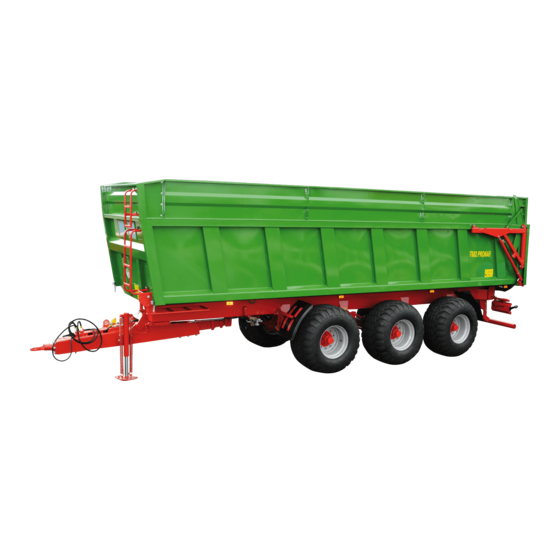
The manual describes the basic principles of safe use and operation of agricultural trailers
Pronar T682 and Pronar T682/1
If the information in this Operator's Manual needs clarification, refer for assistance to the sale
point where the machine was purchased or to the Manufacturer.
MANUFACTURER'S ADDRESS:
CONTACT TELEPHONES
PRONAR Sp. z o.o.
ul. Mickiewicza 101A
17-210 Narew
+48 085 681 63 29
+48 085 681 63 81
this Operator's Manual and observe
+48 085 681 64 29
+48 085 681 63 82
all
Advertisement
Table of Contents

Related Manuals for PRONAR T682/1


Summary of Contents for PRONAR T682/1
- Page 1 The manual describes the basic principles of safe use and operation of agricultural trailers Pronar T682 and Pronar T682/1 If the information in this Operator's Manual needs clarification, refer for assistance to the sale point where the machine was purchased or to the Manufacturer.
- Page 2 SYMBOLS APPEARING IN THIS OPERATOR'S MANUAL Information, descriptions of danger and precautions and also recommendations and prohibitions associated with user safety instructions are marked: and also preceded by the word "DANGER.” Failure to observe the instructions may endanger the machine operator's or other person's health or life. Vital information and instructions that must be observed are by the symbol: and also preceded by the word "IMPORTANT".
- Page 3 DIRECTIONS USED IN THIS OPERATOR'S MANUAL Left side – side to the left hand of the operator facing in the direction of machine's forward travel. Right side – side to the right hand of the operator facing in the direction of machine's forward travel.
-
Page 6: Table Of Contents
TABLE OF CONTENTS 1 BASIC INFORMATION IDENTIFICATION 1.1.1 TRAILER IDENTIFICATION 1.1.2 AXLE IDENTIFICATION 1.1.3 LIST OF SERIAL NUMBERS INTENDED USE EQUIPMENT TERMS & CONDITIONS OF WARRANTY TRANSPORT 1.11 1.5.1 SHIPPING BY ROAD 1.11 1.5.2 INDEPENDENT SHIPPING BY THE USER 1.13 ENVIRONMENTAL RISK 1.14 WITHDRAWAL FROM USE... - Page 7 3 DESIGN AND OPERATION TECHNICAL SPECIFICATION TRAILER CONSTRUCTION 3.2.1 CHASSIS 3.2.2 LOAD BOX 3.2.3 ELECTRICAL SYSTEM 3.2.4 MAIN BRAKE 3.10 3.2.5 PARKING BRAKE 3.15 3.2.6 HYDRAULIC TIPPER SYSTEM 3.15 3.2.7 TAILGATE LIFTING HYDRAULIC SYSTEM 3.17 3.2.8 WHEEL LOCK HYDRAULIC SYSTEM 3.18 4 CORRECT USE PREPARING THE TRAILER FOR WORK...
- Page 8 5.2.2 CHECK WHEEL AXLE BEARINGS FOR SLACKNESS 5.2.3 ADJUST THE PLAY OF THE AXLE BEARINGS 5.2.4 INSTALL AND REMOVE WHEEL, INSPECT WHEEL NUT TIGHTNESS. 5.2.5 CHECK AIR PRESSURE IN TYRES, TECHNICAL CONDITION OF TYRES AND STEEL RIMS 5.2.6 CHECK THICKNESS OF BRAKE SHOE LININGS 5.2.7 ADJUSTMENT OF MECHANICAL BRAKES 5.10 5.2.8 REPLACEMENT OF PARKING BRAKE CABLE AND ADJUSTMENT OF...
- Page 9 5.9.1 AXLES 5.32 5.9.2 DRAWBAR 5.33 5.9.3 SUSPENSION 5.34 5.9.4 TIGHTENING TORQUE FOR NUT AND BOLT CONNECTIONS 5.36 5.10 ADJUSTMENT OF DRAWBAR POSITION 5.37 5.11 MAINTENANCE OF SUSPENSION SYSTEM 5.39 5.12 TROUBLESHOOTING 5.39 5.12.1 TROUBLESHOOTING 5.39...
-
Page 11: Basic Information
SECTION BASIC INFORMATION... -
Page 12: Identification
Pronar T682, Pronar T682/1 SECTION 1 1.1 IDENTIFICATION 1.1.1 TRAILER IDENTIFICATION FIGURE 1.1 Location of the nameplate and vehicle identification number (VIN) (1) nameplate, (2) example of vehicle identification number... -
Page 13: Axle Identification
SECTION 1 Pronar T682, Pronar T682/1 The trailer is marked with a nameplate (1) and a Vehicle Identification Number (2). The VIN and the nameplate are located on the plug of the right longitudinal member of the frame figure (1.1). When purchasing the machine make sure that the numbers on the machine agree with the numbers stated in the WARRANTY BOOK and in the sales documents. -
Page 14: List Of Serial Numbers
Pronar T682, Pronar T682/1 SECTION 1 FIGURE 1.2 Location of the axle nameplate (1) nameplate, (2) wheel axle 1.1.3 LIST OF SERIAL NUMBERS TABLE 1.2 List of serial numbers SERIAL NUMBER OF FRONT AXLE SERIAL NUMBER OF CENTRAL AXLE SERIAL NUMBER OF REAR AXLE... -
Page 15: Intended Use
SECTION 1 Pronar T682, Pronar T682/1 In the event of ordering a replacement part or in the case of the appearance of problems it is often essential to give the serial number of the agricultural trailer or the serial number of the axle, therefore it is recommended that these numbers are inscribed in the table (1.2). - Page 16 Pronar T682, Pronar T682/1 SECTION 1 IMPORTANT The trailer must not be used for purposes other than those for which it is intended. DO NOT: • transport people, animals, hazardous materials, chemically aggressive loads that will corrode the structural elements of the trailer (causing corrosion of steel, destruction of paint coat, dissolving plastic elements and destruction of rubber elements etc.),...
- Page 17 SECTION 1 Pronar T682, Pronar T682/1 The trailer may only be used by persons, who: • are familiar with the contents of this publication and with the contents of the agricultural tractor Operator's Manual, • have been trained in trailer operation and work safety, •...
-
Page 18: Equipment
Pronar T682, Pronar T682/1 SECTION 1 CONTENTS UNIT REQUIREMENTS Turning interlock hydraulic system Hydraulic oil L HL 32 Lotos System pressure rating Oil demand: PTO speed 1.3 EQUIPMENT TABLE 1.4 Equipment EQUIPMENT • OPERATOR'S MANUAL, WARRANTY BOOK Rotating drawbar eye ∅50 •... -
Page 19: Terms & Conditions Of Warranty
Information concerning tyres is provided at the end of this manual in ANNEX A. 1.4 TERMS & CONDITIONS OF WARRANTY PRONAR Sp. z o.o. Narew guarantees the reliable operation of the machine when it is used according to its intended purpose as described in the OPERATOR'S MANUAL. The repair period is specified in the WARRANTY BOOK. - Page 20 Pronar T682, Pronar T682/1 SECTION 1 • tyres, • seals, • bearings. The warranty service only applies to such cases as: mechanical damage which is not the user's fault, factory defects of parts, etc. Demand that the seller carefully and accurately fills out the WARRANTY BOOK and warranty repair coupons.
-
Page 21: Transport
SECTION 1 Pronar T682, Pronar T682/1 1.5 TRANSPORT The machine is prepared for sale completely assembled and does not require packing. Packing is only required for the machine's technical documentation and any extra accessories. The trailer is delivered to the user either transported on a vehicle or, after being attached to a tractor, independently (trailer towed with a tractor). - Page 22 Pronar T682, Pronar T682/1 SECTION 1 FIGURE 1.3 Transport lugs (1) transport lug, (2) upper longitudinal frame IMPORTANT Do not attach or hitch the trailer by drawbar eye, absorber springs or other structural elements that are not sufficiently strong to withstand such a load.
-
Page 23: Independent Shipping By The User
SECTION 1 Pronar T682, Pronar T682/1 A correctly secured machine does not change its position with regard to the transporting vehicle. The securing elements must be selected according to the guidelines of the Manufacturer of these elements. In case of doubt apply a greater number of securing straps in order to secure the load. -
Page 24: Environmental Risk
Pronar T682, Pronar T682/1 SECTION 1 IMPORTANT Before transporting independently, the tractor unit driver must carefully read this Operator's Manual and observe its recommendations. 1.6 ENVIRONMENTAL RISK A hydraulic oil leak constitutes a direct threat to the natural environment owing to its limited biodegradability. -
Page 25: Withdrawal From Use
SECTION 1 Pronar T682, Pronar T682/1 The hydraulic system of the trailer is filled with L-HL32 Lotos hydraulic oil. IMPORTANT Waste oil should only be taken to the appropriate facility dealing with the re-use of this type of waste. Do NOT dispose of or pour oil into sewerage drains or water reservoirs. - Page 26 Pronar T682, Pronar T682/1 SECTION 1 1.16...
-
Page 27: Safety Advice
SECTION SAFETY ADVICE... -
Page 28: Safety Information
Manufacturer may invalidate the warranty. • Use close fitting protective clothing. • Any modification to the trailer frees PRONAR Narew from any responsibility for damage or detriment to health which may arise as a result. -
Page 29: Hitching And Unhitching From Tractor
SECTION 2 Pronar T682, Pronar T682/1 • Before using the machine always check its technical condition, and in particular: technical condition of the drawbar, systems, safety guards and air pressure in tyres. • Hitching and unhitching the trailer may only take place when the machine is immobilised by use of the parking brake and it is not loaded. -
Page 30: Hydraulic System And Pneumatic System
Pronar T682, Pronar T682/1 SECTION 2 • The machine unhitched from tractor must be immobilised with parking brake. If the machine is positioned on a slope, it should be additionally secured against moving by placing chocks under the machine's wheels. Terminals of hydraulic, electrical and pneumatic conduits should be protected against contamination. - Page 31 SECTION 2 Pronar T682, Pronar T682/1 • Incorrect load distribution and overloading the machine may cause the trailer to tip over or cause damage to its components. • Do NOT climb on load box during loading and unloading. • Unloading and loading of trailer may only take place when the machine is positioned on level and hard surface and connected to tractor.
-
Page 32: Cleaning, Maintenance And Adjustment
Pronar T682, Pronar T682/1 SECTION 2 • When closing or opening the rear grain chute gate, be very careful to avoid crushing your fingers. • Do NOT go or place hand between open tailgate and load box. 2.1.5 CLEANING, MAINTENANCE AND ADJUSTMENT •... - Page 33 SECTION 2 Pronar T682, Pronar T682/1 • Servicing and repair work should be carried out in line with the general principles of workplace health and safety. In the event of injury, the wound must be immediately cleaned and disinfected. In the event of more serious injuries, seek a doctor's advice.
-
Page 34: Safe Driving
Pronar T682, Pronar T682/1 SECTION 2 • After completing work associated with lubrication, remove excess oil or grease. The trailer should be kept clean and tidy. • Exercise caution when climbing on top of the load box. Climbing on top of the load box is possible by use of ladders placed on the front wall, extension and also folding steps inside the load box. - Page 35 SECTION 2 Pronar T682, Pronar T682/1 FIGURE 2.1 Mounting place for the slow-moving vehicle warning sign (1) slow-moving vehicle warning sign • If the trailer is the last vehicle in the group, a slow-moving vehicle warning sign should be placed on the trailer's tailgate.
- Page 36 Pronar T682, Pronar T682/1 SECTION 2 FIGURE 2.2 Method of placing chocks • Do NOT attempt to climb on the trailer while driving. • Do NOT park the trailer on a slope. • Before driving off check that the parking brake is released, the braking force regulator is positioned in the proper position (applies to pneumatic systems with manual three-position regulator).
-
Page 37: Tyres
SECTION 2 Pronar T682, Pronar T682/1 • Reckless driving and excessive speed may cause accidents. 2.1.7 TYRES • When working with tyres, the trailer should be immobilised with parking brake and secured against rolling by placing chocks under wheel. Wheels can be taken off the trailer axle only when the trailer is not loaded. - Page 38 Pronar T682, Pronar T682/1 SECTION 2 • After connecting shaft ensure that it is correctly and safely connected to the tractor and to the machine. • Do NOT use the securing chains to support the shaft while machine is parked or being transported.
-
Page 39: Description Of Residual Risk
Pronar T682, Pronar T682/1 2.1.9 DESCRIPTION OF RESIDUAL RISK Pronar Sp. z o. o. in Narew has made every effort to eliminate the risk of accidents. There is, however, a certain residual risk, which could lead to an accident, and this is connected mainly with the actions described below: •... - Page 40 If any are destroyed or damaged, they must be replaced with new. Information and warning decals may be purchased directly from the Manufacturer or your PRONAR dealer. Part numbers of information decals are given under pictogram description in table (2.1) and in SPARE PARTS LIST. New assemblies, changed during repair, must be labelled once again with the appropriate safety signs.
- Page 41 SECTION 2 Pronar T682, Pronar T682/1 ITEM SAFETY SYMBOL DESCRIPTION Grease the machine according to the recommendations in the OPERATOR'S MANUAL 104N-00000004 Maximum static drawbar load 103RPN-00.00.00.02 IMPORTANT Danger of getting caught by the rotating drive shaft. 78RPN-00000005 Maximum PTO speed.
- Page 42 Pronar T682, Pronar T682/1 SECTION 2 ITEM SAFETY SYMBOL DESCRIPTION Note Danger of electric shock. Keep a safe distance from overhead electric power lines during unloading. 58RPN-00.00.020 Danger of crushing the whole body. Keep a safe distance from the tailgate.
- Page 43 SECTION 2 Pronar T682, Pronar T682/1 ITEM SAFETY SYMBOL DESCRIPTION Marking of trailer attachment points during transport. 58RPN-00.00.019 Maximum design speed. 204N-00000008 2.17...
- Page 44 Pronar T682, Pronar T682/1 SECTION 2 FIGURE 2.3 Locations of information and warning decals 2.18...
-
Page 45: Design And Operation
SECTION DESIGN AND OPERATION... - Page 46 Pronar T682, Pronar T682/1 SECTION 3 3.1 TECHNICAL SPECIFICATION TABLE 3.1 Standard equipment specification CONTENTS UNIT T682 T682/1 Dimensions 9,900 Length 2,550 Width 3,330 Height Load box dimensions 8,000 Inner length mm / mm 2,200 / 2250 Internal width: front / rear...
-
Page 47: Trailer Construction
SECTION 3 Pronar T682, Pronar T682 3.2 TRAILER CONSTRUCTION 3.2.1 CHASSIS FIGURE 3.1 Chassis, front view (1) lower frame, (2) drawbar, (3) drawbar spring, (4) cable support, (5) drawbar eye, (6) parking stand, (7) load box support, (8) mudguard Trailer chassis consists of sub-assemblies indicated on figures (3.1) and (3.2). Lower frame (1) is a structure welded from steel sections. - Page 48 Pronar T682, Pronar T682/1 SECTION 3 The rear part of the frame has a rear protection (4) - figure (3.2), a trailer lighting assembly attached to the light support beam (7), and a rear hitch (5). The trailer suspension consists of two steering axles (2) and one fixed axle (1), which are attached to taper leaf springs with U-bolts.
-
Page 49: Load Box
SECTION 3 Pronar T682, Pronar T682 3.2.2 LOAD BOX FIGURE 3.3 Load box – front view (1) load box, (2) set of wall extensions, (3) window, (4) platform ladder, (5) extension ladder The trailer load box (1) is a welded structure made from steel plate and shapes. – figure (3.3). - Page 50 Pronar T682, Pronar T682/1 SECTION 3 FIGURE 3.4 Load box – rear view (1) tailgate, (2) damper, (3) chute, (4) tailgate wing, (5) rod In the rear part of the load box there is the tailgate (1) which is opened and closed using tailgate hydraulic system.
-
Page 51: Electrical System
SECTION 3 Pronar T682, Pronar T682 3.2.3 ELECTRICAL SYSTEM The trailer's electrical system is designed for supply of 12 V DC. The electrical system consists of two independently operating systems: • Electrical lighting system • power supply and solenoid valve control system. - Page 52 Pronar T682, Pronar T682/1 SECTION 3 TABLE 3.3 List of electrical component markings SYMBOL NAME OF COMPONENT ZP / ZL Rear light assembly, right / left side Front seven pin socket Rear seven pin socket TOP / TOL Rear clearance light, right / left...
- Page 53 SECTION 3 Pronar T682, Pronar T682 FIGURE 3.6 Electrical lighting system diagram...
-
Page 54: Main Brake
Pronar T682, Pronar T682/1 SECTION 3 FIGURE 3.7 Connection socket X7P 3.2.4 MAIN BRAKE The trailer is equipped with one of the three types of main brake: • double conduit pneumatic system with three position regulator, figure (3.8) – standard equipment, •... - Page 55 SECTION 3 Pronar T682, Pronar T682 FIGURE 3.8 Diagram of double conduit pneumatic system with manual regulator FIGURE 3.9 Diagram of double conduit pneumatic system with automatic regulator FIGURE 3.10 Hydraulic system diagram 3.11...
- Page 56 Pronar T682, Pronar T682/1 SECTION 3 TABLE 3.5 List of symbols used on the diagrams SYMBOL MEANING Pneumatic connection (plug) Pneumatic connection with cut-off valve (socket) Air filter Drain valve Main control valve Relay valve Automatic regulator of braking force...
- Page 57 SECTION 3 Pronar T682, Pronar T682 FIGURE 3.11 Brake pneumatic cylinders (1) membrane cylinder, (2) control connection, (3) short fork, (4) long fork, (5) pneumatic conduit, (6) plug FIGURE 3.12 Brake cylinder design (1) front cover, (2) rear cover, (3) membrane, (4) spring, (5) cylinder rod, (6) clamping ring Valve used in the system is equipped with a circuit causing the brakes to be applied when trailer is disconnected from the tractor - figure (3.13).
- Page 58 Pronar T682, Pronar T682/1 SECTION 3 connected to the tractor, the device automatically applying the brakes changes its position to allow normal brake operation. Three-step brake force regulator (2)- figure (3.13), adjusts braking force depending on setting. Switching to a suitable working mode is done manually by the machine operator using the lever (4) prior to moving off.
-
Page 59: Parking Brake
SECTION 3 Pronar T682, Pronar T682 3.2.5 PARKING BRAKE FIGURE 3.14 Parking brake (1) brake crank mechanism The parking brake is used for immobilising the trailer while parking. Brake crank mechanism (1) is welded to the front beam of the lower frame and is connected with expander shaft levers by means of steel cables and a tensioning lever. - Page 60 Pronar T682, Pronar T682/1 SECTION 3 FIGURE 3.15 Hydraulic tipping system design (1) oil tank, (2) tipping cylinder, (3) transmission, (4) oil filter, (5) filler plug , (6) oil pump , (7) supply line, (8) return line, (9) solenoid valve block, (10) oil level indicator The 100-litre oil tank is located between the bottom frame side longitudinal members.
-
Page 61: Tailgate Lifting Hydraulic System
SECTION 3 Pronar T682, Pronar T682 FIGURE 3.16 Hydraulic tipping system diagram The hydraulic system of the trailer is filled with L-HL32 Lotos hydraulic oil. 3.2.7 TAILGATE LIFTING HYDRAULIC SYSTEM The hydraulic system is designed for remote control of the tailgate operation from the position of the agricultural tractor operator. -
Page 62: Wheel Lock Hydraulic System
Pronar T682, Pronar T682/1 SECTION 3 FIGURE 3.17 Tailgate hydraulic system diagram 3.2.8 WHEEL LOCK HYDRAULIC SYSTEM As standard the trailer is equipped with two passively steered steering axles. Axle design enables easier cornering and easier manoeuvring on marshy terrain, due to which there is less tyre wear on machine. - Page 63 SECTION 3 Pronar T682, Pronar T682 FIGURE 3.18 Construction and design of steering lock hydraulic system (1) locking cylinder, (2) steering axle, (3) hydraulic quick coupler The turning lock hydraulic system was filled with L-HL32 Lotos oil. 3.19...
- Page 64 Pronar T682, Pronar T682/1 SECTION 3 3.20...
-
Page 65: Correct Use
SECTION CORRECT USE... -
Page 66: Preparing The Trailer For Work
Pronar T682, T682/1 SECTION 4 4.1 PREPARING THE TRAILER FOR WORK 4.1.1 PRELIMINARY INFORMATION The trailer is supplied to the user completely assembled and does not require additional mounting operations of machine sub-assemblies. The manufacturer guarantees that the machine is fully operational and has been checked according to quality control procedures and is ready for use. -
Page 67: Prepare The Trailer
SECTION 4 Pronar T682, T682/1 IMPORTANT The seller is obliged to conduct the first start up of the trailer in the presence of the user. The user trained by the seller is not released from the obligation to carefully read this Operator's Manual and PTO shaft manual. -
Page 68: Preparing The Trailer For Normal Use
Pronar T682, T682/1 SECTION 4 • Switch on individual lights, check correct operation of electrical system. • Release tractor's parking brake. Perform test drive. While driving, check the operation of the trailer brake. • Stop tractor (do not turn off the engine), immobilise tractor with parking brake. -
Page 69: Hitching And Unhitching The Trailer
SECTION 4 Pronar T682, T682/1 • Install the slow-moving vehicle warning sign - if the trailer is used on public roads. • Check the oil level in the tank and add oil if necessary. DANGER Careless and incorrect use and operation of the trailer, and failure to follow instructions in this operator's manual is dangerous to your health. - Page 70 Pronar T682, T682/1 SECTION 4 Reverse tractor, hitch trailer to appropriate hitch tractor, check hitch lock protecting machine against accidental unhitching. agricultural tractor equipped with automatic coupler, ensure that the hitching operation is completed and that drawbar eye is secured.
- Page 71 SECTION 4 Pronar T682, T682/1 Just before driving off, remove chocks from under the trailer's wheels and release parking brake. IMPORTANT The trailer must not be used when not in working order. When turning, connecting conduits must hang loosely and not become tangled with moving elements of machine and tractor.
-
Page 72: Loading And Securing Load
Pronar T682, T682/1 SECTION 4 If the trailer is equipped with a double conduit pneumatic system, first disconnect the red conduit and then disconnect the yellow conduit. Disconnect proper conduit of the hydraulic braking system from the tractor's socket. Disconnect the steering lock hydraulic lines. - Page 73 SECTION 4 Pronar T682, T682/1 IMPORTANT Always try to distribute the load uniformly in the load box. Do NOT exceed the trailer's maximum carrying capacity. Due to various densities of materials, the use of the total load box capacity may lead to exceeding permissible carrying capacity of the trailer.
- Page 74 Pronar T682, T682/1 SECTION 4 WEIGHT BY VOLUME TYPE OF MATERIAL kg/m³ Building materials: cement 1 200 – 1 300 dry sand 1,350 – 1,650 wet sand 1,700 – 2,050 solid bricks 1,500 – 2,100 hollow bricks 1 000 – 1 200 stones 1,500 –...
- Page 75 SECTION 4 Pronar T682, T682/1 WEIGHT BY VOLUME TYPE OF MATERIAL kg/m³ cut dry straw in gathering trailer 50 - 90 cut dry straw in stack 40 - 100 baled straw (lightly crushed) 80 - 90 baled straw (heavily crushed)
- Page 76 Pronar T682, T682/1 SECTION 4 WEIGHT BY VOLUME TYPE OF MATERIAL kg/m³ peas 650 - 750 lentils 750 - 860 runner beans 780 - 870 barley 600 - 750 clover 700 - 800 grass 360 - 500 maize 700 - 850...
- Page 77 SECTION 4 Pronar T682, T682/1 Bulk materials Loading bulk materials is normally conducted with the use of loaders or conveyors and possibly loading manually. Do not load bulk materials to a height greater than that of side walls or extensions. On completion of loading, the load should be evenly spread over the whole surface of the load box.
- Page 78 Pronar T682, T682/1 SECTION 4 Hazardous loads DANGER If it is necessary to carry permitted hazardous materials, acquaint yourself with the regulations concerning transport of hazardous materials in force in the given country and also the regulations of the ADR agreement.
-
Page 79: Transport The Load
SECTION 4 Pronar T682, T682/1 DANGER If there is a danger of load packaging moving, do NOT transport this type of material. A moving load constitutes a serious hazard during travel for the tractor driver and other road users. Materials which may cause corrosion of steel, chemical damage or react in any other way negatively affecting the trailer structure may be transported only on condition of appropriate load preparation. - Page 80 Pronar T682, T682/1 SECTION 4 • Make sure that the trailer is correctly attached to the tractor and tractor's hitch is properly secured. • The trailer must not be overloaded, loads must be uniformly distributed so that the maximum permissible axle loads are not exceeded. The trailer's maximum carrying capacity must not be exceeded as this can damage the trailer and pose a risk to the operator or other road users.
-
Page 81: Unloading
SECTION 4 Pronar T682, T682/1 • Speed must be sufficiently reduced before making a turn or driving on an uneven road or a slope. • When driving, avoid sharp turns especially on slopes. IMPORTANT Travelling with a high-volume load over ruts, ditches, roadside slopes etc. - Page 82 Pronar T682, T682/1 SECTION 4 after unloading, lower the load box by pressing the button (4), clean the edges of the floor and walls, close the tailgate by pressing the button (5) or close the slide gate, press the button (1) to turn the...
- Page 83 SECTION 4 Pronar T682, T682/1 FIGURE 4.3 Chute (1) slide gate, (2) chute, (3) lever, (4) locking bolt While unloading bulky materials be especially careful. Do NOT tip load box on uneven or wet ground and move and jerk trailer during unloading. Bulky materials are normally difficult to unload.
-
Page 84: Proper Use And Maintenance Of Tyres
Pronar T682, T682/1 SECTION 4 4.6 PROPER USE AND MAINTENANCE OF TYRES When working with tyres, the trailer should be secured against rolling by placing chocks under the wheels. Wheels can be taken off the trailer axle only when the trailer is not loaded. -
Page 85: Maintenance
SECTION MAINTENANCE... -
Page 86: Preliminary Information
Pronar T682, Pronar T682/1 SECTION 5 5.1 PRELIMINARY INFORMATION When using the trailer, regular inspections of its technical condition and the performance of maintenance procedures are essential, which keep the machine in good technical condition. In connection with this the user of the trailer is obliged to perform all the maintenance and adjustment procedures defined by the Manufacturer. -
Page 87: Check Wheel Axle Bearings For Slackness
SECTION 5 Pronar T682, Pronar T682 Procedure relating to: • changing grease in axle bearings, • changing bearings, hub seals, • repairing wheel axle, • may be performed by specialist workshops. 5.2.2 CHECK WHEEL AXLE BEARINGS FOR SLACKNESS FIGURE 5.1... - Page 88 Pronar T682, Pronar T682/1 SECTION 5 Raise the wheel (opposite to the side where chocks are placed). Lifting jack should be positioned in the place indicated by the arrow in figure (5.1). Lifting jack must be suitable for machine weight.
-
Page 89: Adjust The Play Of The Axle Bearings
SECTION 5 Pronar T682, Pronar T682 INSPECT • After travelling the first 1,000 km. • Every six months of use or every 25,000 km. Check condition of hub cover, if necessary replace with a new cover. Only inspect bearings for looseness, when the machine is hitched to a tractor. The machine may not be loaded. - Page 90 Pronar T682, Pronar T682/1 SECTION 5 The nut must not be excessively tightened. Do not apply excessive pressure because working conditions of the bearings may deteriorate. Secure castellated nut with cotter pin and mount the hub cap. Delicately tap the hub cap with rubber or wooden mallet.
- Page 91 SECTION 5 Pronar T682, Pronar T682 Dismount wheel. Install wheel Clean axle pins and nuts of contamination. Do not grease thread of nuts and pins. Check condition of pins and nuts, if necessary replace. Place wheel on hub, tighten nuts so that wheel rim tightly fits the hub.
-
Page 92: Check Air Pressure In Tyres, Technical Condition Of
Pronar T682, Pronar T682/1 SECTION 5 WHEEL TIGHTENING TORQUE BODY WEIGHT (F) ARM LENGTH (L) [Nm] [kg] 0.58 0.61 0.65 0.74 IMPORTANT Wheel nuts must not be tightened with impact wrench because of danger of exceeding permissible tightening torque, the consequence of which may be breaking the connection thread or breaking off the hub pin. -
Page 93: Check Thickness Of Brake Shoe Linings
SECTION 5 Pronar T682, Pronar T682 DANGER Damaged tyres or wheels may be the cause of a serious accident. While checking pressure pay attention to technical condition of wheels and tyres. Look carefully at tyre sides and check the condition of tread. In case of mechanical damage consult the nearest tyre service and check whether the tyre defect requires tyre replacement. -
Page 94: Adjustment Of Mechanical Brakes
Pronar T682, Pronar T682/1 SECTION 5 FIGURE 5.6 Check brake shoe linings (1) brake drum, (2) disc, (3) inspection openings, (G) thickness of brake shoe lining INSPECT Thickness of brake shoe linings should be checked every 6 months. 5.2.7 ADJUSTMENT OF MECHANICAL BRAKES Considerable wear of brake shoe linings results in increased brake cylinder rod stroke and worse braking efficiency. - Page 95 SECTION 5 Pronar T682, Pronar T682 During braking, the brake cylinder piston stroke should be within the specified operating range and the angle between brake cylinder piston (1) and expander arm (3) should be about 90° – compare figure (5.8). Trailer wheels must brake simultaneously.
- Page 96 Pronar T682, Pronar T682/1 SECTION 5 During dismantling of cylinder fork (6) remember or mark the original setting of the cylinder fork pin (7) (L1 distance - front axle, L2 distance - rear axle). Mounting position depends on the type of the braking system and size of the trailer tyres. It is selected by the manufacturer and cannot be changed - see table (5.2).
- Page 97 SECTION 5 Pronar T682, Pronar T682 FIGURE 5.8 Principle of brake adjustment (1) cylinder piston rod, (2) brake cylinder membrane, (3) expander arm, (4) adjustment bolt, (5) cylinder fork, (6) fork pin, (7) brake cylinder bracket, (A) mark on the cylinder piston rod at brake...
- Page 98 Pronar T682, Pronar T682/1 SECTION 5 Remember or mark the original position of pin (6) – figure (5.8), brake cylinder fork (5) in expander arm opening (3). Dismantle brake cylinder fork pin (6). Check if the brake cylinder piston rod moves freely and within the whole nominal range.
-
Page 99: Replacement Of Parking Brake Cable And Adjustment Of
SECTION 5 Pronar T682, Pronar T682 If the brake cylinder piston rod stroke is outside the proper operating range, repeat the adjustment. 5.2.8 REPLACEMENT OF PARKING BRAKE CABLE AND ADJUSTMENT OF CABLE TENSION. Proper operation of the parking brake is dependent on the effectiveness of the axle brake and the correct brake cable tension. - Page 100 Pronar T682, Pronar T682/1 SECTION 5 Install new cable, adjust cable tension. Adjustment of parking brake cable tension Hitch trailer to tractor. Park machine and tractor on level surface. Prevent the trailer from rolling by placing chocks under the wheels. Immobilise tractor with parking brake.
-
Page 101: Pneumatic System Maintenance
SECTION 5 Pronar T682, Pronar T682 INSPECT • Every 12 months. 5.3 PNEUMATIC SYSTEM MAINTENANCE 5.3.1 PRELIMINARY INFORMATION Work connected with repair, replacement or regeneration of system components (brake cylinders, conduits, control valve, braking force regulator, etc.) should be entrusted to specialist establishments, having the appropriate technology and qualifications for this type of work. -
Page 102: Inspection Of The System
Pronar T682, Pronar T682/1 SECTION 5 Start the tractor in order to supplement air in the trailer braking system tank. In single line systems air pressure should amount to approx. 5.8 to 6.5 bar. In double conduit systems air pressure should amount to approx. 6.5 bar. -
Page 103: Cleaning The Air Filters
SECTION 5 Pronar T682, Pronar T682 INSPECT • Each time during tightness inspection. 5.4 CLEANING THE AIR FILTERS Depending on trailer working conditions, but not less than once in three months, take out and clean air filter elements, which are located in pneumatic system connection conduits. Inserts are used many times and are not subject to changing unless they are mechanically damaged. -
Page 104: Drain Water From Air Tank
Pronar T682, Pronar T682/1 SECTION 5 Required maintenance Reduce pressure in supply conduit. Pressure in conduit can be reduced by pressing the head of the pneumatic connection until resistance is felt. Remove securing slide (1). Hold the filter cover (2) with the other hand. After removing slide lock, the cover is pushed off by the spring located in the filter housing. -
Page 105: Clean The Drain Valves
SECTION 5 Pronar T682, Pronar T682 5.4.2 CLEAN THE DRAIN VALVES DANGER Release air from the air tank before dismantling drain valve. Required maintenance Completely reduce pressure in air tanks. Reduction of pressure in the tanks can be achieved by tilting the stem of drain valve. -
Page 106: Hydraulic System Maintenance
Pronar T682, Pronar T682/1 SECTION 5 If the trailer is unhitched from the tractor, connections should be protected by cover or placed in their designated socket. Before the winter, it is recommended to preserve the seal with special preparations (e.g. silicon grease for rubber elements). -
Page 107: Check Technical Condition Of Hydraulic Couplers And Sockets
SECTION 5 Pronar T682, Pronar T682 Start the tractor and cycle the hydraulic cylinders several times (tailgate and steering lock). Leave the cylinders in the maximally extended position. Switch off the tractor engine and check the hydraulic cylinders. Switch on tractor engine again and start PTO drive , cause tipping of load box. -
Page 108: Replace Hydraulic Lines
Pronar T682, Pronar T682/1 SECTION 5 INSPECT • Each time before hitching trailer to tractor. 5.5.4 REPLACE HYDRAULIC LINES INSPECT • every 4 years. Rubber hydraulic lines must be replaced every 4 years regardless of their technical condition. This should be done in specialised workshops. - Page 109 SECTION 5 Pronar T682, Pronar T682 ITEM LUBRICATION POINT Tailgate locking hook bolt Load box tipping bolt Tailgate wing bolt Drawbar spring Drawbar rocker arm pin Drawbar pin Slide gate guides Leaf springs Leaf spring absorber sliding surfaces Expander lever ¹...
- Page 110 Pronar T682, Pronar T682/1 SECTION 5 careful washing and inspection, mount lubricated elements. If necessary, bearing and seals should be replaced with new parts. Lubrication of axle bearings shall be performed at least once in 2 years. TABLE 5.3 Recommended lubricants...
- Page 111 SECTION 5 Pronar T682, Pronar T682 FIGURE 5.12 Trailer's lubrication points 5.27...
- Page 112 Pronar T682, Pronar T682/1 SECTION 5 FIGURE 5.13 Trailer's lubrication points 5.28...
-
Page 113: Consumables
SECTION 5 Pronar T682, Pronar T682 5.6.1 CONSUMABLES Hydraulic oil Always adhere to the principle that the oil in the trailer hydraulic system and in the tractor hydraulic system are of the same type. In the event of application of different types of oil make certain that both hydraulic substances may be mixed together. -
Page 114: Trailer Cleaning
Pronar T682, Pronar T682/1 SECTION 5 DANGER Oil fires should be quenched with the use of carbon dioxide, foam or steam extinguishers. Do not use water to quench oil fires. Lubricants For heavily loaded parts it is recommended to apply lithium greases with addition of molybdenum disulphide (MOS ) or graphite. - Page 115 SECTION 5 Pronar T682, Pronar T682 leaf springs and drawbar shock absorber, etc. High pressure water jets may get inside the machine and cause mechanical damage or corrosion. • For cleaning and maintenance of plastic coated surfaces it is recommended to use clean water or special preparations designed for this purpose.
-
Page 116: Storage
Pronar T682, Pronar T682/1 SECTION 5 5.8 STORAGE • Trailer should be kept in a closed or roofed building. • If the machine will not be used for a long time, it is essential to protect it from adverse weather conditions, especially those which initiate corrosion of steel, have aggressive impact on anticorrosion coating and accelerate tyre ageing. -
Page 117: Connections
SECTION 5 Pronar T682, Pronar T682 • Steering axle lock cylinders mounting. • Steering axle shock absorber mounting. • Tie rod connection. • Cap nuts and lock nuts on the steering lock cylinders. • Lock nuts at the tie rod ends. - Page 118 Pronar T682, Pronar T682/1 SECTION 5 FIGURE 5.14 Drawbar (1) U-bolt, (2) bracket, (3) spring pin, (4) rocker arm pin, (5) drawbar pin, (6) rocker arm bracket 5.9.3 SUSPENSION Suspension bolt connections Connections of nuts and U bolts (1) securing the spring to the axle.
- Page 119 SECTION 5 Pronar T682, Pronar T682 FIGURE 5.15 Absorber suspension (1) U-bolt, (2) rocker arm, (3) spring, (4) adjustable control rod, (5) rigid control rod After tightening the bolts securing the control rods, the washer (1) - figure (5.16) must not...
- Page 120 Pronar T682, Pronar T682/1 SECTION 5 Connection tightening torques - figure (5.15) 550 – 560 Nm M24x2 550 – 560 Nm M24x2.5 450 – 500 Nm Tighten the other bolted connections according to the table (5.5) INSPECT • After first travel with load.
- Page 121 SECTION 5 Pronar T682, Pronar T682 10.9 THREAD METRIC Md [Nm] 1,050 1,450 2,100 – strength class according to DIN ISO 898 standard hydraulic lines should be tightened using torque of 50 – 70 Nm. FIGURE 5.17 Bolt with metric thread (1) strength class, (d) thread diameter 5.10 ADJUSTMENT OF DRAWBAR POSITION...
- Page 122 Pronar T682, Pronar T682/1 SECTION 5 FIGURE 5.18 Drawbar control (1) drawbar, (2) drawbar mounting plate, (3) suspension spring arm, (4) rocker arm support , (5) rocker arm pin Immobilise trailer with parking brake. Prevent the trailer from rolling by placing chocks under the wheels.
- Page 123 SECTION 5 Pronar T682, Pronar T682 Adjust the height of the jack and adjust the rocker arm support to the desired position. Tighten the rocker arm support to the plate (2). You can also adjust drawbar position by transferring the rocker arm pin (5) to the corresponding hole of the spring (3) rocker arm to obtain different height settings.
- Page 124 Pronar T682, Pronar T682/1 SECTION 5 FAULT POSSIBLE CAUSE REMEDY Brake system conduits not Connect brake conduits (applies connected to pneumatic systems) Applied parking brake Release parking brake. Damaged pneumatic Replace. Problem with moving off system connection conduits Tighten, replace washers or seal Leaking connections sets, replace conduits.
- Page 125 SECTION 5 Pronar T682, Pronar T682 FAULT POSSIBLE CAUSE REMEDY Check cylinder piston rod (bending, corrosion), check Damaged or contaminated cylinder for tightness (cylinder cylinder piston rod seal), if necessary, repair or replace the cylinder. Check and reduce cylinder load, if Excessive cylinder loading necessary.
- Page 126 Pronar T682, Pronar T682/1 SECTION 5 FAULT POSSIBLE CAUSE REMEDY Prolonged use of tyre with Regularly check air pressure in low air pressure. tyres. Side crack. Excessive loading of the Check weight of load while trailer. loading. Too frequent driving over...
- Page 127 SECTION 5 Pronar T682, Pronar T682 FAULT POSSIBLE CAUSE REMEDY Connect the line Controller harness disconnected. Damaged Check the system socket and socket or 3-pole plug. plug. 5.43...
- Page 128 Pronar T682, Pronar T682/1 SECTION 5 5.44...
- Page 129 NOTES …………………………………………………………………………………………………………… …………………………………………………………………………………………………………… …………………………………………………………………………………………………………… …………………………………………………………………………………………………………… …………………………………………………………………………………………………………… …………………………………………………………………………………………………………… …………………………………………………………………………………………………………… …………………………………………………………………………………………………………… …………………………………………………………………………………………………………… …………………………………………………………………………………………………………… …………………………………………………………………………………………………………… …………………………………………………………………………………………………………… …………………………………………………………………………………………………………… …………………………………………………………………………………………………………… …………………………………………………………………………………………………………… …………………………………………………………………………………………………………… …………………………………………………………………………………………………………… …………………………………………………………………………………………………………… …………………………………………………………………………………………………………… …………………………………………………………………………………………………………… …………………………………………………………………………………………………………… …………………………………………………………………………………………………………… …………………………………………………………………………………………………………… ……………………………………………………………………………………………………………...
- Page 130 …………………………………………………………………………………………………………… …………………………………………………………………………………………………………… …………………………………………………………………………………………………………… …………………………………………………………………………………………………………… …………………………………………………………………………………………………………… …………………………………………………………………………………………………………… …………………………………………………………………………………………………………… …………………………………………………………………………………………………………… …………………………………………………………………………………………………………… …………………………………………………………………………………………………………… …………………………………………………………………………………………………………… …………………………………………………………………………………………………………… …………………………………………………………………………………………………………… …………………………………………………………………………………………………………… …………………………………………………………………………………………………………… …………………………………………………………………………………………………………… …………………………………………………………………………………………………………… …………………………………………………………………………………………………………… …………………………………………………………………………………………………………… …………………………………………………………………………………………………………… …………………………………………………………………………………………………………… …………………………………………………………………………………………………………… …………………………………………………………………………………………………………… …………………………………………………………………………………………………………… …………………………………………………………………………………………………………… …………………………………………………………………………………………………………… ……………………………………………………………………………………………………………...
- Page 131 ANNEX A TYRE WHEEL DISC 385/65R22.5 160F TL (regenerated) 11.75x22.5 ET=-30 385/65 R22.5 TL 11.75x22.5 ET=-30 425/65 R22.5 18PR (regenerated) 13.00x22.5" 425/65 R22.5 TL 13.00x22.5" 445/65R22.5 169F TL (regenerated) 14.00x22.5 ET=0 550/60-22.5 171 A8 16.00x22.5 ET=0 600/55-22.5 16PR 169 A8 20.00x22.5H2 ET=-40 620/50R22.5 172 A8 20.00x22.5H2 ET=-40...
Need help?
Do you have a question about the T682/1 and is the answer not in the manual?
Questions and answers