Table of Contents
Advertisement
Quick Links
INSTALLATION and OPERATION MANUAL
18 Frame
IMPORTANT!
Read all instructions in this manual before operating pump.
As a result of Crane Pumps & Systems, Inc., constant product improvement program,
product changes may occur. As such Crane Pumps & Systems reserves the right to
change product without prior written notification.
A Crane Co. Company
420 Third Street
Piqua, Ohio 45356
Phone: (937) 778-8947
Fax: (937) 773-7157
www.cranepumps.com
BARNES
BARNES
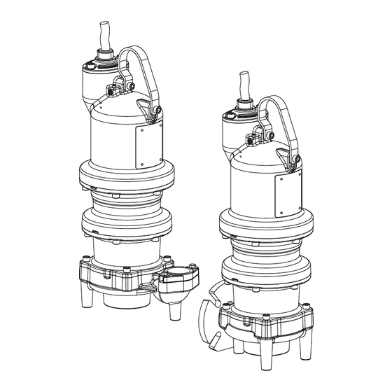
Submersible Grinder Pump
83 West Drive, Brampton
Ontario, Canada L6T 2J6
Phone: (905) 457-6223
Fax: (905) 457-2650
®
BLADE NGV
Vertical Discharge
3 - 7.5HP, 3450RPM
BLADE NGVH
Horizontal Discharge
3 - 7.5HP, 3450RPM
BLADE NGVHH
Horizontal Discharge
7.5 - 10HP, 3450RPM
This product may be covered by one
or more of the following patents and
other patent(s) pending:
US Patent 7, 931, 473
Form No. 141182N-Rev. E
Advertisement
Table of Contents

Subscribe to Our Youtube Channel
Related Manuals for Crane BARNES NGV Series


Summary of Contents for Crane BARNES NGV Series
- Page 1 Read all instructions in this manual before operating pump. As a result of Crane Pumps & Systems, Inc., constant product improvement program, product changes may occur. As such Crane Pumps & Systems reserves the right to change product without prior written notification. A Crane Co. Company...
-
Page 2: Table Of Contents
START-UP REPORT ......................27 - 28 Other brand and product names are trademarks or registered trademarks of their respective holders. ® Barnes is a registered trademark of Crane Pumps & Systems, Inc 1995,1997,1998,1/2004, 4/05 , 1/06, 3/06, 9/06, 12/06, 2/07... -
Page 3: Safety First
IMPORTANT! - Crane Pumps & Systems, Inc. is not responsible for losses, injury, or death resulting from a WARNING! - DO NOT pump hazardous materials failure to observe these safety precautions, misuse or (flammable, caustic, etc.) unless the pump is specifically... - Page 4 USER GUIDE USER GUIDE The grinder pump generates sufficient Congratulations on your purchase of a Barnes pressure to pump this slurry from your home to UltraGRIND™ grinder pump system. With the wastewater plant. proper care and by following a few simple Power Failure guidelines your grinder pump will give you many years of dependable service.
-
Page 5: Section A: General Information
A-4) Service Centers: For the location of the nearest Barnes Service Center, check your Barnes representative or Crane Pumps & Systems, Inc., Service Department in Piqua, Ohio, telephone (937) 778-8947 or Crane Pumps & Systems Canada, in Brampton, Ontario, (905) 457- 6223. - Page 6 B-1.1) Submergence: BARNES Pumps manufactures a break away fit dis- It is recommended that the pump be operated in the charge system designed to allow the submersible waste- Continuous Duty Submergence condition and the sump water pump to be installed or removed without requiring liquid level should never be less than the Minimum Sub- personnel to enter the wet well.
-
Page 7: Electrical Data
B-3) Liquid Level Controls: be mounted outside the sump or be of at least Nema 7 It is recommended to use a liquid level control system that allows explosion proof construction if located within the wet well. A listed the on and off point to be separated by at least twelve inches. water and vapor tight seal fitting MUST be used in conduit leaving An additional set point (lag point) should be incorporated with an the wet well to prevent moisture and gasses from reaching the... - Page 11 THREE PHASE 460-575 VOLT AC (orange molded plug) THREE PHASE 460-575 VOLT AC (orange molded plug) MOISTURE AND TEMPERATURE SENSORS MOISTURE AND TEMPERATURE SENSORS Power Cable Power Cable Motor Lead ID Motor Lead ID Power Cable Power Cable Lead ID Lead ID Green (Ground) Green...
- Page 12 TYPICAL POWER CIRCUIT FIGURE 3b Recommended Breaker & Heater Sizes Model No. Volts Capacitor Kit Start Relay Start Capacitor Run Capacitor NGV3072 / 208/230 141361 MARS 64 297MFD @ 330V 40MFD @ 440V NGVH3072 NGV5072 / 208/230 141361 MARS 64 297MFD @ 330V 40MFD @ 440V NGVH5072...
- Page 13 TYPICAL THERMAL PROTECTION WIRING DIAGRAM FIGURE 4 B-4.3) Overload Protection: B-4.4) Moisture Sensors: Current sensing overloads must be provided in the pump A normally open (N/O) detector is installed in the pump seal control panel and should be properly sized for the full load chamber, which will detect any moisture present, and a current of the pump.
-
Page 14: Section: C Start-Up Operation
FIGURE 5 It is advisable that all three phase control panels be C-2.2) Test Procedure For Moisture Sensor Control: purchased from the factory. With a moisture detection control, a normally closed push button and neon indicating lamp is typically provided as a SECTION: C START-UP OPERATION means of checking the moisture sensing components. -
Page 15: Section D: Preventative Maintenance
C-3.2) Insulation Test: 3. If oil is found to be clean and uncontaminated (measure above 15 KV. breakdown), refill the seal chamber as per Before the pump is put into service, an insulation (megger) section E-1.2. test should be performed on the motor. The resistance values 4. - Page 16 E-2) Impeller and Volute Service: E-2.1) Disassembly and Inspection: To clean out the volute (11), or clean out or replace impeller (6), disconnect power, remove cap screws (2) then vertically lift motor assembly from the pump body (11). Clean out the volute, if necessary, clean and examine impeller (6) for pitting or wear, replace if required.
-
Page 17: Section: F Replacement Parts
SECTION: F REPLACEMENT PARTS F-1 ORDERING REPLACEMENT PARTS: When ordering replacement parts, ALWAYS furnish the following information: 1. Pump serial number and date code. (Paragraph F-4) 2. Pump model number. (Paragraph F-3) 3. Pump part number. (Paragraph F-2) 4. Part description. 5. -
Page 18: Troubleshooting
TROUBLESHOOTING CAUTION ! Always disconnect the pump from the electrical power source before handling. If the system fails to operate properly, carefully read instructions and perform maintenance recommendations. If operating problems persist, the following chart may be of assistance in identifying and correcting them: MATCH “CAUSE”... -
Page 19: Vertical Discharge
Cross Sections Vertical Discharge FIGURE 9 Horizontal Discharge FIGURE 10... -
Page 20: Exploded Views, (Fig. 11 & 12)
Exploded Views APPLY GREEN LOCTITE RC603 APPLY GREEN TORQUE TO: LOCTITE RC603 45 ±1.4FT/LBS TORQUE TO: 45 ±1.4FT/LBS Vertical Horizontal FIGURE 12 FIGURE 11... -
Page 21: Parts Lists
PARTS LIST Outboard Seal Kit .........See Chart Hardware Kit ..........141535 Impeller Attachment Kit ......141534 Cord Attachment Kit ......140152-18 Leg Kit ............125506 Volute—Shredding Ring Kit ....See Chart ITEM PART NO. DESCRIPTION MATERIAL No Resale Driver Assembly 141057 Cutter, Radial, 3.10” Dia., Drive 440 Stainless Steel 136284-70 Screw, SHCS, M12 x 1.75 x 70... - Page 22 Power Cable Chart Length Cord O.D. +/- Part No. Volt Max. Amps Cord Size (feet) .02in (.5mm) 125496XC 208-240 31.7 12/4 - 18/4 0.86in (22.0mm) 125496XF 208-240 31.7 12/4 - 18/4 0.86in (22.0mm) 125496XJ 208-240 31.7 12/4 - 18/4 0.86in (22.0mm) 125496XL 208-240 31.7...
- Page 23 MOVEABLE ASSEMBLY PARTS LIST Moveable Assembly .......141065B ITEM PART NO. DESCRIPTION MATERIAL 074535 Fitting, Moveable, Cast Iron Bronze 15-19-1 Nut, Hex, 5/16-18 Stainless Steel 062941 Washer, Flat, 5/16, .10” Stainless Steel 026322 Washer, Lock, 5/16 18-8 Stainless Steel 107357 Bolt, U, 5/16-18, 2.50” Stainless Steel 141063 Bracket, Moveable, 2”...
- Page 24 Notes...
-
Page 25: Warranty
Crane Pumps & Systems, Inc. Distributor. RETURNED GOODS RETURN OF MERCHANDISE REQUIRES A “RETURNED GOODS AUTHORIZATION”. CONTACT YOUR LOCAL CRANE PUMPS & SYSTEMS, INC. DISTRIBUTOR. Products Returned Must Be Cleaned, Sanitized, Or Decontaminated As Necessary Prior To Shipment, To Insure That Employees Will Not Be Exposed To Health Hazards In Handling Said Material.
Need help?
Do you have a question about the BARNES NGV Series and is the answer not in the manual?
Questions and answers