NEC NP1200 User Manual
Nec np1200: user guide
Hide thumbs
Also See for NP1200:
- Specifications (2 pages) ,
- User manual (115 pages) ,
- Command manual (60 pages)

Related Manuals for NEC NP1200


Summary of Contents for NEC NP1200
- Page 1 LCD Projector NP3200/NP2200/NP1200 User’s Manual The NP3200 is not distributed in North America.
- Page 2 (3) Great care has been taken in the preparation of this manual; however, should you notice any questionable points, errors or omissions, please contact us. (4) Notwithstanding article (3), NEC will not be responsible for any claims on loss of profit or other matters deemed to result from using the Projector.
-
Page 3: Safety Cautions
Important Information Safety Cautions Precautions Please read this manual carefully before using your NEC NP3200/NP2200/NP1200 projector and keep the manual handy for future reference. CAUTION To turn off main power, be sure to remove the plug from power outlet. The power outlet socket should be installed as near to the equipment as possible, and should be easily accessible. - Page 4 The Federal Communications Commission does not allow any modifications or changes to the unit EXCEPT those specified by NEC Display Solutions of America, Inc. in this manual. Failure to comply with this government regulation could void your right to operate this equipment. This equipment has been tested and found to comply with the limits for a Class B digital device, pursuant to Part 15 of the FCC Rules.
-
Page 5: Important Safeguards
Important Information Important Safeguards These safety instructions are to ensure the long life of your projector and to prevent fire and shock. Please read them carefully and heed all warnings. Installation • Do not place the projector in the following conditions: - on an unstable cart, stand, or table. - Page 6 Important Information Fire and Shock Precautions • Ensure that there is sufficient ventilation and that vents are unobstructed to prevent the build-up of heat inside your projector. Allow at least 4 inches (10 cm) of space between your projector and a wall. •...
-
Page 7: Remote Control Precautions
Important Information CAUTION • Always carry your projector by the carrying handle. Before doing so, be sure to lock the carrying handle in place. To lock the carrying handle, see “To lock the carrying handle” on page 6. • Do not use the tilt-foot for purposes other than originally intended. Misuses such as using the tilt foot to carry or hang (from the wall or ceiling) the projector can cause damage to the projector. - Page 8 Important Information About High Altitude mode • Set [FAN MODE] to [HIGH ALTITUDE] when using the projector at altitudes approximately 5500 feet/1600 me- ters or higher. Using the projector at altitudes approximately 5500 feet/1600 meters or higher without setting to [HIGH ALTI- TUDE] can cause the projector to overheat and the protector could shut down.
-
Page 9: Table Of Contents
2. Installation and Connections ..............12 Setting Up the Screen and the Projector ..............12 Selecting a Location [NP3200/NP2200/NP1200]........... 12 Making Connections ....................13 Connecting Your PC or Macintosh Computer ............13 Connecting an External Monitor ................16 Connecting Your DVD Player with Component Output ........... - Page 10 Specifications ......................89 Cabinet Dimensions ....................91 Screen Size and Projection Distance ................92 [NP3200/NP2200/NP1200] ..................92 Pin Assignments of D-Sub COMPUTER 1 Input Connector ........94 Mini D-Sub 15 Pin Connector ................94 Compatible Input Signal List ..................95...
- Page 11 Table of Contents 7 PC Control Codes and Cable Connection ..............96 PC Control Codes ....................96 Cable Connection ....................97 PC Control Connector (D-SUB 9P) ................ 97 8 Troubleshooting Check List ..................98 9 TravelCare Guide ....................... 100...
-
Page 12: Important Information
Power cable VGA signal cable (For North America: 7N080236) (7N520073) (For Europe and other countries: 7N080022) NEC Projector CD-ROM User’s Manual (7N951381) • Important Information (For North America: 7N8P9891) (For Other countries than North America: 7N8P9891 and 7N8P9901) • Quick Setup Guide (7N8P9881) •... -
Page 13: Introduction To The Projector
PC control port (D-Sub 9 Pin) and LAN support. With input and output flexibility, long lamp life and a full function remote, the NP3200/NP2200/NP1200 lets you enjoy larger than life viewing from a com- pact and easy to setup and use projector. -
Page 14: About This User's Manual
1. Introduction • A variety of input ports and a comprehensive array of system control interfaces This projector supports input signals on the following ports: BNC, DVI-D, 15pin D-Sub, composite and S-video. • Wall Color Correction Built-in Wall Color Correction presets provide for adaptive color correction when projecting onto non-white screen material (or a wall). -
Page 15: Part Names Of The Projector
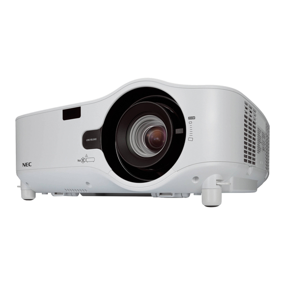
1. Introduction Part Names of the Projector Front/Top Lens Shift Dial (Right / Left, Up / Down) (→ page 25) Controls (→ page 7) Focus Ring (→ page 26) Remote Sensor Ventilation (inlet) / Filter (→ page 10) (→ page 77) LENS RELEASE Button Built-in Security Slot ( (→... -
Page 16: Bottom
1. Introduction Bottom Anti-theft Screw for Lens Carrying Handle (→ page 85) Carrying the Projector Always carry your projector by the handle. Ensure that the power cable and any other cables connecting to video sources are disconnected before moving the projector. - Page 17 1. Introduction To lock the carrying handle 1. Carefully place the projector on its end. 2. Pull up the carrying handle with the catch pressed down. 3. Press down the left and right locks to set the carrying handle in place. •...
-
Page 18: Top Features
1. Introduction Top Features ) (ON / STAND BY) ( → page 5. SOURCE Button ( → page 23) 1. POWER Button ( 21, 31) 6. AUTO ADJUST Button ( → page 30) NOTE: To turn on the projector, press and hold this button 7. -
Page 19: Terminal Panel Features
PC Control (HDCP compatible) ( → page 15) Utility Pro 4 contained on the supplied NEC Projec- AUDIO IN (Stereo Mini Jack) ( → page 15) tor CD-ROM. To do so you must first have PC Con- trol Utility Pro 4 installed on your PC ( →... -
Page 20: Part Names Of The Remote Control
1. Introduction Part Names of the Remote Control 11. ID SET Button (→ page 68) 12. Numeric Keypad Button/CLEAR Button (→ page 68) 13. FREEZE Button (→ page 32) 14. AV-MUTE Button (→ page 32) 15. MENU Button (→ page 50) 16. -
Page 21: Battery Installation
1. Introduction Battery Installation Press firmly and slide the battery Install new batteries (AAA). En- Slip the cover back over the bat- cover off. sure that you have the batteries’ teries until it snaps into place. Do polarity (+/−) aligned correctly. not mix different types of batter- ies or new and old batteries. -
Page 22: Remote Control Precautions
1. Introduction Remote Control Precautions • Handle the remote control carefully. • If the remote control gets wet, wipe it dry immediately. • Avoid excessive heat and humidity. • Do not heat, take apart, or throw batteries into fire. • If you will not be using the remote control for a long time, remove the batteries. •... -
Page 23: Installation And Connections
Setting Up the Screen and the Projector Selecting a Location [NP3200/NP2200/NP1200] The further your projector is from the screen or wall, the larger the image. The minimum size the image can be is approximately 30 inches (0.76 m) measured diagonally when the projector is roughly 41 inches (1.0 m) from the... -
Page 24: Making Connections
Usually, the combination of the “Fn” key along with one of the 12 function keys gets the external display to come on or off. For example, NEC laptops use Fn + F3, while Dell laptops use Fn + F8 key combinations to toggle through external display selections. - Page 25 2. Installation and Connections • Select the source name for its appropriate input connector after turning on the projector. SOURCE button on the projector Input connector Button on the remote control cabinet COMPUTER 1 IN COMPUTER 1 (COMPUTER 1) COMPUTER 2 IN COMPUTER 2 (COMPUTER 2) COMPUTER 3 (DVI-D) IN...
- Page 26 2. Installation and Connections When Viewing a DVI Digital Signal To project a DVI digital signal, be sure to connect the PC and the projector using a DVI-D signal cable (not supplied) before turning on your PC or projector. Turn on the projector first and select COMPUTER 3 from the source menu before turning on your PC.
-
Page 27: Connecting An External Monitor
2. Installation and Connections Connecting an External Monitor (or COMPUTER 2 IN / COMPONENT IN) COMPUTER 1 IN AUDIO OUT MONITOR OUT Stereo mini-plug audio cable (not supplied) Stereo mini-plug audio cable (not supplied) VGA signal cable (supplied) VGA signal cable (not supplied) AUDIO PHONE You can connect a separate, external monitor to your projector to simultaneously view on a monitor the RGB ana-... -
Page 28: Connecting Your Dvd Player With Component Output
2. Installation and Connections Connecting Your DVD Player with Component Output AUDIO IN COMPUTER 1 IN 15-pin - to - RCA (female) × 3 cable adapter (ADP-CV1E) Audio Equipment Component video RCA × 3 AUDIO IN cable (not supplied) DVD player Stereo mini plug - to - RCA audio cable (not supplied) AUDIO OUT... -
Page 29: Connecting Your Vcr
2. Installation and Connections Connecting Your VCR VIDEO IN S-VIDEO IN AUDIO IN S-Video cable (not supplied) Video cable (not supplied) Audio equipment S-VIDEO VIDEO AUDIO IN VIDEO OUT AUDIO OUT Audio cable (not supplied) TIP: You can connect a video cable to the “G/Y” connector of the COMPUTER 2 IN (BNC) connectors to display a VCR source. To do so, from the menu, select [SETUP] →... -
Page 30: Connecting To A Network
2. Installation and Connections Connecting to a Network Example of LAN connection Example of wired LAN connection Server LAN cable (not supplied) NOTE: Use a Category 5 or higher LAN cable. -
Page 31: Connecting The Supplied Power Cable
2. Installation and Connections Connecting the Supplied Power Cable Connect the supplied power cable to the projector. First connect the supplied power cable’s three-pin plug to the AC IN of the projector, and then connect the other plug of the supplied power cable in the wall outlet. To wall outlet ←... -
Page 32: Projecting An Image (Basic Operation)
1 second. is removed. ( → page 86) NOTE: When no signal is available, the NEC logo, blue (default), or black screen will be displayed. When the projector displays the NEC logo, a blue or black screen, the projector will automatically switch to [ECO MODE]. -
Page 33: Note On Startup Screen (Menu Language Select Screen)
3. Projecting an Image (Basic Operation) Note on Startup screen (Menu Language Select screen) When you first turn on the projector, you will get the Startup menu. This menu gives you the opportunity to select one of the 21 menu languages. To select a menu language, follow these steps: 1. -
Page 34: Selecting A Source
3. Projecting an Image (Basic Operation) Selecting a Source Selecting the computer or video source NOTE: Turn on the computer or video source equipment connected to the projector. Selecting from Source List Press and quickly release the SOURCE button on the projector cabinet to dis- play the Source list. -
Page 35: Adjusting The Picture Size And Position
3. Projecting an Image (Basic Operation) Adjusting the Picture Size and Position Use the lens shift dials, the adjustable tilt foot levers, the zoom lever or the focus ring to adjust the picture size and position. Adjusting the position of a projected image Adjusting the focus [Lens shift] [Focus ring]... -
Page 36: Adjusting The Position Of A Projected Image
3. Projecting an Image (Basic Operation) Adjusting the position of a projected image • Rotate the lens shift dial. NOTE: The lens shift dial for LEFT-RIGHT cannot be rotated one-half turn or more. Do not over rotate it or it may break. NOTE: Shifting the lens to the maximum in two directions combined will cause the edges of the image to become dark or will cause some shadows. -
Page 37: Adjusting The Focus (Focus Ring)
3. Projecting an Image (Basic Operation) Adjusting the focus (Focus ring) • Rotate the focus ring to make focus adjustment. Focus ring Finely adjusting the size of an image (Zoom lever) • Rotate the zoom lever to adjust the image size on the screen. Zoom lever... -
Page 38: Adjusting The Tilt Foot
3. Projecting an Image (Basic Operation) Adjusting the Tilt Foot 1. Lift the front edge of the projector. CAUTION: Do not try to touch the ventilation outlet during Tilt Foot adjustment as it can become heated while the projector is turned on and after it is turned off. -
Page 39: Correcting Keystone Distortion
3. Projecting an Image (Basic Operation) Correcting Keystone Distortion Correcting Keystone Distortion If the screen is tilted vertically, keystone distortion becomes large. Proceed with the following steps to correct keystone distortion POWER AUTO ADJ. COMPUTER S-VIDEO VIEWER VIDEO CLEAR ID SET AV-MUTE FREEZE MENU... -
Page 40: Adjusting From The Menu
3. Projecting an Image (Basic Operation) Adjusting from the menu 1. Press the MENU button. The menu will be displayed. 2. Press the button to select [SETUP] and press the ENTER button. The [GENERAL] screen will be displayed. 3. Press the button to select [KEYSTONE]. 4. -
Page 41: Optimizing An Rgb Image Automatically
3. Projecting an Image (Basic Operation) Optimizing an RGB Image Automatically Adjusting the Image Using Auto Adjust Optimizing an RGB image automatically. Press the AUTO ADJUST (AUTO ADJ.) button to optimize an RGB image automatically. This adjustment may be necessary when you connect your computer for the first time. [Poor picture] [Normal picture] NOTE:... -
Page 42: Turning Off The Projector
3. Projecting an Image (Basic Operation) 7 Turning off the Projector To turn off the projector: 1. Press the POWER (ON/STAND BY) button on the projector cabi- net or the POWER OFF button on the remote control. The [POWER OFF / ARE YOU SURE? / CARBON SAVINGS- SES- SION 0.000[g-CO2]] message will appear. -
Page 43: Convenient Features
4. Convenient Features Turning off the Image and Sound Press the AV-MUTE button to turn off the image and sound for a short period of time. Press again to restore the image and sound. NOTE: • Even though the image is turned off, the menu still remains on the screen. •... -
Page 44: Changing Eco Mode
Select this mode to increase the lamp life (approx. Steady Green light LAMP POWER AUTO ADJ. 80% Brightness on NP3200 and approx. 88% STATUS Brightness on NP2200/NP1200). COMPUTER VIDEO S-VIDEO VIEWER To turn on the [ECO MODE], do the following: ID SET CLEAR 1. -
Page 45: Checking Energy-Saving Effect [Carbon Meter]
4. Convenient Features Checking Energy-Saving Effect [CARBON METER] This feature will show energy-saving effect in terms of CO emission reduction (kg) when the projector’s [ECO MODE] is set to [ON]. This feature is called as [CARBON METER]. ( → page 33) There are two messages: [TOTAL CARBON SAVINGS] and [CARBON SAVINGS-SESSION]. -
Page 46: Preventing The Unauthorized Use Of The Projector [Security]
4. Convenient Features Preventing the Unauthorized Use of the Projector [SECURITY] A keyword can be set for your projector using the Menu to avoid operation by an unauthorized user. When a key- word is set, turning on the projector will display the Keyword input screen. Unless the correct keyword is entered, the projector cannot project an image. - Page 47 4. Convenient Features 7. Type in the same combination of buttons and press the ENTER button. The confirmation screen will be displayed. 8. Select [YES] and press the ENTER button. The SECURITY function has been enabled. To turn on the projector when [SECURITY] is enabled: 1.
- Page 48 4. Convenient Features To disable the SECURITY function: 1. Press the MENU button. The menu will be displayed. 2. Select [SETUP] → [INSTALLATION] → [SECURITY] and press the ENTER button. The OFF/ON menu will be displayed. 3. Select [OFF] and press the ENTER button. The KEYWORD CONFIRMATION screen will be displayed.
-
Page 49: Using The Optional Remote Mouse Receiver (Np01Mr)
4. Convenient Features 7 Using the Optional Remote Mouse Receiver (NP01MR) The optional remote mouse receiver enables you to operate your computer’s mouse functions from the remote con- trol. It is a great convenience for clicking through your computer-generated presentations. Connecting the remote mouse receiver to your computer If you wish to use the remote mouse function, connect the mouse receiver and computer. - Page 50 4. Convenient Features Operating your computer’s mouse from the remote control You can operate your computer’s mouse from the remote control. PAGE / Button: scrolls the viewing area of the window or to move to the previous or next slide in PowerPoint on your computer.
-
Page 51: Network Setting By Using An Http Browser
IP address of the projector has been set in the “HOSTS” file of the computer being used. Example 1: When the host name of the projector has been set to “pj.nec.co.jp”, access is gained to the network setting by specifying http://pj.nec.co.jp/index.html... -
Page 52: Network Settings
4. Convenient Features Network Settings http://<the projector’s IP address> /index.html DHCP ����������������������������Enabling this option automatically assigns an IP address to the projector from your DHCP server� Dis- abling this option allows you to register the IP address or subnet mask number obtained from your network administrator�... - Page 53 DOMAIN NAME �������������������������������Type in the domain name of the network connected to the projector� Up to 60 alphanu- meric characters can be used� If the domain name is unknown, type in the right side of @ in the sender’s address� Example: nec� com ALERT MAIL ������������������������������������Checking [ENABLE] will turn on the Alert Mail feature�...
-
Page 54: Using The Vga Signal Cable To Operate The Projector (Virtual Remote)
9 Using the VGA Signal Cable to Operate the Projector (Virtual Remote) Using the utility software “Virtual Remote Tool” included on the companion NEC Projector CD-ROM, Virtual Remote screen (or toolbar) can be displayed on your computer screen. This will help you perform operations such as projector’s power on or off and signal selection via the VGA signal cable. - Page 55 1 Insert the accompanying NEC Projector CD-ROM into your CD-ROM drive. The folders in NEC Projector CD-ROM will be displayed. If the folders are not displayed, right-click the CD/DVD drive icon in Windows’ “Computer” (or “My Computer”) and select “Open”.
- Page 56 4. Convenient Features TIP: Uninstalling Virtual Remote Tool Preparation: Exit Virtual Remote Tool before uninstalling. To uninstall Virtual Remote Tool, the Windows user account must have “Administrator” privilege (Windows 7, Windows Vista and Windows 2000) or “Computer Administrator” privilege (Windows XP). •...
- Page 57 4. Convenient Features Step 3: Start Virtual Remote Tool 1 Double-click the shortcut icon on the Windows Desktop. When Virtual Remote Tool starts for the first time, “Easy Setup” window will be displayed. Follow the instructions on the screens When “Easy Setup” is completed, the Virtual Remote Tool screen will be displayed. TIP: •...
- Page 58 The Help screen will be displayed. • Displaying the help file using the Start Menu. 1. Click “Start”. “All programs” or “Programs”. “NEC Projector User Supportware”. “Virtual Remote Tool”. and then “Virtual Remote Tool Help” in this order. The Help screen will be displayed.
-
Page 59: Controlling The Projector Over A Lan (Pc Control Utility Pro 4)
Controlling the Projector over a LAN (PC Control Utility Pro 4) Using the utility software “PC Control Utility Pro 4” included on the companion NEC Projector CD-ROM, the projec- tor can be controlled from a computer over a LAN. - Page 60 Read “Virtual Remote Tool” as “PC Control Utility Pro 4” ( → page 45) Step 3: Start PC Control Utility Pro 4 Click “Start” → “All programs” or “Programs” → “NEC Projector User Supportware” → “PC Control Utility Pro 4” → “PC Control Utility Pro 4”.
-
Page 61: Using On-Screen Menu
5. Using On-Screen Menu Using the Menus NOTE: The on-screen menu may not be displayed correctly while interlaced motion video image is projected. 1. Press the MENU button on the remote control or the projector cabinet to display the menu. NOTE: The commands such as ENTER, EXIT, , ... -
Page 62: Menu Elements
5. Using On-Screen Menu Menu Elements Slide bar Solid triangle Available buttons Source Highlight Radio button High Altitude symbol Thermometer symbol Off Timer remaining time Key Lock symbol Menu windows or dialog boxes typically have the following elements: Highlight �����������������������������Indicates the selected menu or item� Solid triangle ����������������������Indicates further choices are available�... -
Page 63: List Of Menu Items
5. Using On-Screen Menu List of Menu Items Some menu items are not available depending on the input source. Menu Item Default Options COMPUTER1 COMPUTER2 SOURCE COMPUTER3 VIDEO S-VIDEO PRESET 1–6 GENERAL HIGH-BRIGHT, PRESENTATION, VIDEO, MOVIE, REFERENCE GRAPHIC, sRGB GAMMA DYNAMIC, NATURAL, BLACK DETAIL CORRECTION... - Page 64 5. Using On-Screen Menu DESKTOP DESKTOP FRONT, CEILING REAR, DESKTOP REAR, ORIENTATION FRONT CEILING FRONT CONTROL PANEL LOCK OFF, ON SECURITY OFF, ON INSTALLATION COMMUNICATION SPEED 19200bps 4800bps, 9600bps, 19200bps REMOTE SENSOR FRONT/BACK FRONT/BACK, FRONT, BACK CONTROL ID 1–254 CONTROL ID NUMBER CONTROL ID OFF, ON...
-
Page 65: Menu Descriptions & Functions [Source]
5. Using On-Screen Menu Menu Descriptions & Functions [SOURCE] COMPUTER1 Selects the computer connected to your COMPUTER 1 IN input connector. NOTE: • When the component input signal is connected to the COMPUTER 1 IN connector, select [COMPUTER1]. • The projector will determine if the input signal is RGB or component signal. COMPUTER2 Selects the computer connected to your COMPUTER 2 IN connectors (BNC ×... -
Page 66: Menu Descriptions & Functions [Adjust]
5. Using On-Screen Menu Menu Descriptions & Functions [ADJUST] [PICTURE] [PRESET] This function allows you to select optimized settings for your projected image. You can adjust neutral tint for yellow, cyan or magenta. There are six factory presets optimized for various types of images. You can also use [DETAIL SETTINGS] to set user adjustable settings to customize each gamma or color. - Page 67 5. Using On-Screen Menu [GENERAL] Storing Your Customized Settings [REFERENCE] This function allows you to store your customized settings in [PRESET 1] to [PRESET 6]. First, select a base preset mode from [REFERENCE], then set [GAMMA CORRECTION] and [COLOR TEMPERA- TURE].
- Page 68 5. Using On-Screen Menu [RESET] The settings and adjustments for [CONTRAST], [BRIGHTNESS], [SHARPNESS], [COLOR], [HUE], and [REFER- ENCE] within [PRESET] will be returned to the factory settings. The settings and adjustments under [DETAIL SETTINGS] within the [PRESET] screen that are not currently select- ed will not be reset.
-
Page 69: Image Options
5. Using On-Screen Menu [IMAGE OPTIONS] Adjusting Clock and Phase [CLOCK/PHASE] This allows you to manually adjust CLOCK and PHASE. CLOCK ������������������� Use this item to fine tune the computer image or to remove any vertical banding that might appear� This function adjusts the clock frequencies that eliminate the horizontal banding in the image�... - Page 70 5. Using On-Screen Menu Adjusting Horizontal/Vertical Position [HORIZONTAL/VERTICAL] Adjusts the image location horizontally and vertically. - An image can be distorted during the adjustment of [CLOCK] and [PHASE]. This is not malfunction. - The adjustments for [CLOCK], [PHASE], [HORIZONTAL], and [VERTICAL] will be stored in memory for the current signal.
- Page 71 5. Using On-Screen Menu Selecting Aspect Ratio [ASPECT RATIO] The term “aspect ratio” refers to the ratio of width to height of a projected image. The projector automatically determines the incoming signal and displays it in its appropriate aspect ratio. •...
- Page 72 5. Using On-Screen Menu Sample image when the appropriate aspect ratio is automatically determined [Computer signal] Aspect ratio of incoming signal 16:9 15:9 16:10 Sample image when the appro- priate aspect ratio is automati- cally determined [Video signal] Aspect ratio of incoming signal Letterbox Squeeze Sample image when the aspect...
- Page 73 5. Using On-Screen Menu [AUDIO] Controlling Sound [VOLUME/BASS/TREBLE/BALANCE] Adjusts the volume, bass and treble level, left and right balance of the projector speaker and AUDIO OUT (Stereo Mini Jack). TIP: [VOLUME] • When no menus appear, the and buttons on the projector cabinet and the VOL. +/− buttons work as a volume control. ( → page 30) [BALANCE] •...
-
Page 74: Menu Descriptions & Functions [Setup]
5. Using On-Screen Menu Menu Descriptions & Functions [SETUP] [GENERAL] Correcting Vertical Keystone Distortion Manually [KEYSTONE] You can correct vertical distortion manually. ( → page 28) TIP: When this option is highlighted, pressing the ENTER button will display its slide bar for adjustment. Saving Vertical Keystone Correction [KEYSTONE SAVE] This option enables you to save your current keystone settings. - Page 75 (approx. 80% Brightness on NP3200 Steady Green light and approx. 88% Brightness on NP2200/ NP1200). NOTE: • The [LAMP LIFE REMAINING] and [LAMP HOURS USED] can be checked in [USAGE TIME]. Select [INFO.] → [USAGE TIME]. ( → page 74) •...
- Page 76 5. Using On-Screen Menu Setting Closed Caption [CLOSED CAPTION] This option sets several closed caption modes that allow text to be superimposed on the projected image of Video or S-Video. OFF ������������������������ This exits the closed caption mode� CAPTION 1-4 ��������� Text is superimposed� TEXT 1-4 ����������������...
- Page 77 5. Using On-Screen Menu Turning On / Off Eco Message [ECO MESSAGE] This option turns on or off the following messages when the projector is turned on. The Eco Message prompts the user to save energy. When [OFF] is selected for [ECO MODE], you will get a mes- sage to prompt you to select [ON] for [ECO MODE].
- Page 78 5. Using On-Screen Menu [INSTALLATION] Selecting Projector Orientation [ORIENTATION] This reorients your image for your type of projection. The options are: desktop front projection, ceiling rear projec- tion, desktop rear projection, and ceiling front projection. DESKTOP FRONT CEILING REAR DESKTOP REAR CEILING FRONT Disabling the Cabinet Buttons [CONTROL PANEL LOCK] This option turns on or off the CONTROL PANEL LOCK function.
- Page 79 5. Using On-Screen Menu Selecting Communication Speed [COMMUNICATION SPEED] This feature sets the baud rate of the PC Control port (D-Sub 9P). It supports data rates from 4800 to 19200 bps. The default is 19200 bps. Select the appropriate baud rate for your equipment to be connected (depending on the equipment, a lower baud rate may be recommended for long cable runs).
- Page 80 5. Using On-Screen Menu 4. Release the ID SET button. The updated CONTROL ID screen will be displayed. NOTE: • The IDs can be cleared in a few days after the batteries are run down or removed. • Accidentally pressing any one of the buttons of the remote control will clear currently specified ID with batteries removed.
- Page 81 5. Using On-Screen Menu [OPTIONS(1)] Setting Auto Adjust [AUTO ADJUST] This feature sets the Auto Adjust mode so that the computer signal can be automatically or manually adjusted for noise and stability. You can automatically make adjustment in two ways: [NORMAL] and [FINE]. OFF ������������������������...
- Page 82 5. Using On-Screen Menu Selecting Signal Format [SIGNAL SELECT] [COMPUTER1], [COMPUTER2] Allows you to set [COMPUTER1] and [COMPUTER2] to automatically detect an incoming RGB or component source such as a computer or DVD player. However there may be some RGB and component signals that the pro- jector is unable to detect.
- Page 83 5. Using On-Screen Menu [OPTIONS(2)] Using Off Timer [OFF TIMER] 1. Select your desired time between 30 minutes and 16 hours: OFF, 0:30, 1:00, 2:00, 4:00, 8:00, 12:00, 16:00. 2. Press the ENTER button on the remote control. 3. The remaining time starts counting down. 4.
- Page 84 5. Using On-Screen Menu Turning On the Projector By Applying Computer Signal [AUTO POWER ON(COMP1/2)] When the projector is in Standby mode, applying a computer signal from a computer connected to the COMPUT- ER1 IN or COMPUTER2 IN input will power on the projector and simultaneously project the computer’s image. This functionality eliminates the need to always use the POWER button on the remote control or the projector cabi- net to power on the projector.
-
Page 85: Menu Descriptions & Functions [Info.]
5. Using On-Screen Menu 7 Menu Descriptions & Functions [INFO.] Displays the status of the current signal and lamp usage. This item has four pages. TIP: Pressing the HELP button on the remote control will show the [INFO.] menu items. The information included is as follows: [USAGE TIME] [LAMP LIFE REMAINING] (%)*... - Page 86 5. Using On-Screen Menu [SOURCE] [SOURCE NAME] [SOURCE INDEX] [HORIZONTAL FREQUENCY] [VERTICAL FREQUENCY] [SIGNAL TYPE] [VIDEO TYPE] [SYNC TYPE] [SYNC POLARITY] [SCAN TYPE] [WIRED LAN] [PROJECTOR NAME] [IP ADDRESS] [SUBNET MASK] [GATEWAY] [MAC ADDRESS] [VERSION] [PRODUCT] [SERIAL NUMBER] [FIRMWARE] Version [DATA] Version [CONTROL ID] (when [CONTROL ID] is set)
-
Page 87: Menu Descriptions & Functions [Reset]
5. Using On-Screen Menu 8 Menu Descriptions & Functions [RESET] Returning to Factory Default [RESET] The RESET feature allows you to change adjustments and settings to the factory preset for a (all) source (s) except the following: [CURRENT SIGNAL] Resets the adjustments for the current signal to the factory preset levels. The items that can be reset are: [PRESET], [CONTRAST], [BRIGHTNESS], [SHARPNESS], [COLOR], [HUE], [CLOCK], [PHASE], [HORIZONTAL], [VERTICAL], [OVERSCAN], and [ASPECT RATIO]. -
Page 88: Maintenance
6. Maintenance This section describes the simple maintenance procedures you should follow to clean the filters and replace the lamp. Cleaning or Replacing the Filter The air-filter sponge keeps dust and dirt from getting inside the projector and should be frequently cleaned. If the filter is dirty or clogged, your projector may overheat. -
Page 89: Cleaning The Cabinet And The Lens
6. Maintenance 2. Gently peel off the filter (sponge) and replace it with the new one. 3. Reinstall the filter cover. • Slip the filter cover back until it snaps into place. 4. Connect the supplied power cable, turn on the Main Power switch and turn on the projector. 5. -
Page 90: Replacing The Lamp
Do not touch them as the pieces of glass may cause injury. If this happens, contact your NEC dealer for lamp replacement. - Page 91 3. Insert a new lamp housing until the lamp housing is plugged into the socket. CAUTION Do not use a lamp other than the NEC replacement lamp NP06LP. Order this from your NEC dealer. Secure it in place with the two screws.
- Page 92 6. Maintenance 4. Reattach the lamp cover. Slip the lamp cover back until it snaps into place. 5. Connect the supplied power cable, turn on the Main Power switch and turn on the projector. 6. Finally, select the menu → [RESET] → [CLEAR LAMP HOURS] to reset the lamp life remaining and lamp usage hours.
-
Page 93: Using Optional Lenses
7. Using Optional Lenses Five optional lenses are available for the NP3200/NP2200/NP1200. See the information described on this page to buy the appropriate lens for your screen size and throw distance. See page for installing the lens. Table of Throw Distances and Screen Sizes for Optional Lenses [NP3200/NP2200/NP1200] NOTE: The values in the tables are design values and may vary. -
Page 94: Lens Shift Adjustable Range
7. Using Optional Lenses Lens Shift Adjustable Range The top right diagram shows the location of the image position in the lens. The lens can be shifted within the shad- ed area as shown using the normal projection position as a starting point. The projector has a lens shift feature that allows you to move the image vertically or horizontally. -
Page 95: Replacing With Optional Lens
If you remove and store the lens, attach the lens cap to the projector to keep off dust and dirt. • Please heed the following information if you own two or more NP3200/NP2200/NP1200 projectors and may in- terchange the standard lenses. - Page 96 7. Using Optional Lenses Install the new lens 1. Insert the lens with the yellow protrusion on top. Yellow Protrusion 2. Rotate the lens clockwise. Rotate the lens until you feel it click into place. Using the anti-theft screw to prevent theft of the lens Tighten the supplied anti-theft screw on the front bottom.
-
Page 97: Appendix
8. Appendix Troubleshooting This section helps you resolve problems you may encounter while setting up or using the projector. Indicator Messages POWER Indicator Indicator Condition Projector Condition Note The main power is off – Blinking light Green 0�5 sec On, The projector is getting ready to turn on�... - Page 98 8. Appendix Common Problems & Solutions (→ “POWER/STATUS/LAMP Indicator” on page 86) Problem Check These Items Does not turn on • Check that the power cable is plugged in and that the power button on the projector cabinet or the remote control or shut down is on�...
- Page 99 Usually, the combination of the “Fn” key along with one of the 12 function keys gets the external display to come on or off. For example, NEC laptops use Fn + F3, while Dell laptops use Fn + F8 key combinations to toggle through external display selections.
-
Page 100: Specifications
LCD Panel NP3200/NP2200/NP1200: 0.8" p-Si TFT active-matrix with Micro Lens Array (Aspect ratio 4:3) Resolution NP3200/NP2200/NP1200: 1024 × 768 pixels*¹ up to UXGA with scaling technology (up to SXGA+ @ 60 Hz on DVI-D) Standard Lens Manual zoom and focus: F1.7–2.2 f=24.4–32.5 mm... - Page 101 Power Consumption NP3200: 428W(100-130V AC)/412W(200-240V AC) in OFF for ECO MODE/345W(100-130V AC)/334W(200-240V AC) in ON for ECO MODE NP2200/NP1200: 396W(100-130V AC)/381W(200-240V AC) in OFF for ECO MODE/345W(100-130V AC)/334W(200-240V AC) in ON for ECO MODE NP3200/NP2200/NP1200: 12W(100-130V AC)/13W(200-240V AC) in NORMAL Mode for STANDBY MODE/0.4W(100-130V AC)/0.5W(200-...
-
Page 102: Cabinet Dimensions
8. Appendix Cabinet Dimensions 399/15.7" Unit: mm/inch... -
Page 103: Screen Size And Projection Distance
This section should be used when considering the distance to the screen and the screen size. The following is an example of when the standard lens is used. [NP3200/NP2200/NP1200] Available projection distances are 1.0 m/41.2 inches for 30" screen to 18 m/718 inches for 500" screen, according to the chart. - Page 104 8. Appendix List of Screen Sizes [NP3200/NP2200/NP1200] List of Screen Sizes Width (H) Height (V) Screen size inch inch Height Screen size (Diagonal) 30" 24.0 0.46 18.0 40" 31.5 23.6 60" 47.2 35.4 80" 63.0 47.2 100" 78.7 59.1 120"...
-
Page 105: Pin Assignments Of D-Sub Computer 1 Input Connector
8. Appendix Pin Assignments of D-Sub COMPUTER 1 Input Connector Mini D-Sub 15 Pin Connector Signal Level Video signal : 0.7Vp-p (Analog) Sync signal : TTL level 14 13 Pin No. RGB Signal (Analog) YCbCr Signal Green or Sync on Green Blue Ground Ground... -
Page 106: Compatible Input Signal List
8. Appendix Compatible Input Signal List Horizontal: 15KHz to 100KHz (RGB: 24KHz or over) Vertical: 50Hz to 120Hz Resolution Frequency H. Refresh Rate Signal (Dots) (kHz) (Hz) VIDEO NTSC 15.73 59.94 15.63 50.00 PAL60 15.73 60.00 SECAM 15.63 50.00 IBM compatible ×... -
Page 107: Pc Control Codes And Cable Connection
8. Appendix 7 PC Control Codes and Cable Connection PC Control Codes Function Code Data POWER ON POWER OFF INPUT SELECT COMPUTER 1 INPUT SELECT COMPUTER 2 INPUT SELECT COMPUTER 3 INPUT SELECT VIDEO INPUT SELECT S-VIDEO PICTURE MUTE ON PICTURE MUTE OFF SOUND MUTE ON SOUND MUTE OFF... -
Page 108: Cable Connection
8. Appendix Cable Connection Communication Protocol Baud rate ������������������������������������������ 19200 bps Data length ��������������������������������������� 8 bits Parity ������������������������������������������������ No parity Stop bit �������������������������������������������� One bit X on/off �������������������������������������������� None Communications procedure ������������� Full duplex NOTE: Depending on the equipment, a lower baud rate may be recommended for long cable runs. PC Control Connector (D-SUB 9P) To TxD of PC To RxD of PC... -
Page 109: Troubleshooting Check List
8. Appendix 8 Troubleshooting Check List Before contacting your dealer or service personnel, check the following list to be sure repairs are needed also by referring to the “Troubleshooting” section in your user’s manual. This checklist below will help us solve your problem more efficiently. - Page 110 Native resolution: Refresh rate: Video adapter: Other: Projector DVD player Video equipment Signal cable VCR, DVD player, Video camera, Video game or other NEC standard or other manufacturer’s cable? Model number: Length: inch/m Manufacturer: Distribution amplifier Model number: Model number: Switcher...
-
Page 111: Travelcare Guide
This warranty allows customers to receive service on their product at 9) Other conditions stipulated in the warranty included with the the NEC and NEC-designated service stations in the countries listed product also apply. herein when temporarily traveling internationally for business or plea- sure. - Page 112 8. Appendix Visual Group Ltd. NEC Corporation of Malaysia Sdn. Bhd. Address: 28 Walls Road Penrose Auckland New Zealand Address: 33rd Floor, Menara TA One, 22, Jalan P. Ram- Telephone: 095250740 lee, 50250 Kuala Lumpur, Malaysia Fax Line: 095809607 Telephone:...
- Page 113 8. Appendix P-1/ Date: TO: NEC or NEC’s Authorized Service Station: (Company & Name with signature) Dear Sir (s), I would like to apply your TravelCare Service Program based on attached registration and qualification sheet and agree with your following conditions, and also the Service fee will be charged to my credit card account, if I don’t return the Loan units within the specified period.
- Page 114 Application Sheet. list price to Credit Cards, which price will be informed by NEC Autho- rized Service Stations. Please see the attached listing of contacts for 1) Repair and Return: each country to arrange for pickup of the loan unit.
- Page 115 © NEC Display Solutions, Ltd. 2009 7N951381...