Table of Contents
Advertisement
Advertisement
Table of Contents

Related Manuals for MSI KT6 Delta-FIS2R


Summary of Contents for MSI KT6 Delta-FIS2R
- Page 1 KT6 Delta MS-6590 (v2.X) ATX Mainboard Version 2.1 G52-M6590XP...
-
Page 2: Fcc-B Radio Frequency Interference Statement
Manual Rev: 2.1 Release Date: May 2004 FCC-B Radio Frequency Interference Statement This equipment has been tested and found to comply with the limits for a class B digital device, pursuant to part 15 of the FCC rules. These limits are designed to provide reasonable protection against harmful interference when the equip- ment is operated in a commercial environment. -
Page 3: Copyright Notice
Copyright Notice The material in this document is the intellectual property of MICRO-STAR INTERNATIONAL. We take every care in the preparation of this document, but no guarantee is given as to the correctness of its contents. Our products are under continual improvement and we reserve the right to make changes without notice. -
Page 4: Safety Instructions
Safety Instructions Always read the safety instructions carefully. Keep this User’s Manual for future reference. Keep this equipment away from humidity. Lay this equipment on a reliable flat surface before setting it up. The openings on the enclosure are for air convection hence protects the equipment from overheating. -
Page 5: Table Of Contents
Safety Instructions ..................iv Chapter 1. Getting Started ............... 1-1 Mainboard Specifications ..............1-2 Mainboard Layout ................1-4 MSI Special Features ................1-5 Super Pack (Optional) ..............1-5 Core Center ................... 1-6 Core Cell™ Chip ................1-8 Live BIOS™ / Live Driver™ ............1-9 D-Bracket™... - Page 6 Back Panel ................... 2-9 Mouse Connector ................. 2-9 Keyboard Connector ..............2-10 USB 2.0 Connectors ..............2-10 Serial Port Connectors: COM A & COM B ......... 2-11 RJ-45 LAN Jack (Optional) ............2-11 Parallel Port Connector: LPT1 ............. 2-12 Audio Port Connectors ............... 2-13 Connectors ..................
- Page 7 PCI Interrupt Request Routing ........... 2-32 Chapter 3. BIOS Setup ................3-1 Entering Setup ..................3-2 Selecting the First Boot Device ............. 3-2 Control Keys ................3-3 Getting Help .................. 3-3 The Main Menu .................. 3-4 Standard CMOS Features ..............3-6 Advanced BIOS Features ..............
-
Page 8: Chapter 1. Getting Started
Getting Started Chapter 1. Getting Started Getting Started Thank you for purchasing KT6 Delta (MS-6590 v2.X) ® ATX mainboard. The KT6 Delta is based on VIA Apollo KT600 & VT8237 chipsets and provides eight USB 2.0 ports for high- speed data transmission, C-Media 9739A chip for 6-channel audio output and one SPDIF pinheader for digital audio transmission. -
Page 9: Mainboard Specifications
† DDR400 memory support maximum 4 banks. † Supports up to 3GB memory size. † As to the “DDR 400/PC3200 Qualified Memory Test list” of KT6 Delta, please visit MSI website (http://www.msi.com.tw) and search the mainboard KT6 Delta for details. Slots †... - Page 10 Getting Started Promise 20378 On-Board (Optional) † Supports Ultra ATA, Serial ATA, Ultra ATA RAID 0 or 1 , Serial ATA RAID 0 or 1, Ultra/Serial ATA RAID 0+1 supported. † Connect up to 2 Serial ATA devices and 2 Ultra ATA 133 devices. On-Board Peripherals †...
-
Page 11: Mainboard Layout
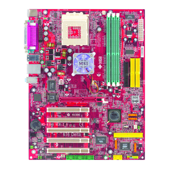
MS-6590 ATX Mainboard Mainboard Layout Top : mouse CFAN1 Bottom: keyboard SOCKET 462 Top : Parallel Port Bottom: COM A COM B ports KT600 Top: LAN jack (Optional) Bottom: USB ports Line-Out Line-In NBFAN1 JPW1 Winbond W83697HF JIR1 AGP Slot BIOS PCI Slot 1 PCI Slot 2... -
Page 12: Msi Special Features
Getting Started MSI Special Features Super Pack (Optional) MSI provides a useful CD which includes 6 powerful and popular utilities for your office professional working and for your home leisure entertainments. Adobe Photoshop Album: The fast and easy way to organize and share your lifetime of photos. -
Page 13: Core Center
MS-6590 ATX Mainboard Core Center The Core Center is a new utility you can find in the CD-ROM disk. The utility is just like your PC doctor that can detect, view and adjust the PC hardware and system status during real time operation. In the left side it shows the current system status including the Vcore, 3.3V, +5V and 12V. - Page 14 Getting Started Left-side: Current system status In the left sub-menu, you can configure the settings of FSB, Vcore, Memory Voltage and AGP Voltage by clicking the radio button in front of each item and make it available (the radio button will be lit as yellow when selected), use the “+”...
-
Page 15: Core Cell Chip
MS-6590 ATX Mainboard Core Cell Chip By diagnosing the current system utilization, the CoreCell™ Chip automatically tunes your motherboard to the optimal state, leading to less noise, longer duration, more power- saving and higher performance. Features of CoreCell™ Speedster -- Advanced O.C. design. -- Superior O.C. -
Page 16: Live Bios™ /Live Driver
BIOS/drivers online so that you don’t need to search for the correct BIOS/driver version throughout the Web site. To use the function, you need to install the “MSI Live Update 2” application. After installation, the “MSI Live Update 2” icon (as shown on the right) will appear on the screen. -
Page 17: D-Bracket™ 2 (Optional)
MS-6590 ATX Mainboard D-Bracket™ 2 (Optional) D-Bracket™ 2 is an external USB bracket integrating four Diagnostic LEDs, which use graphic signal display to help users understand their system. The LEDs provide up to 16 combinations of signals to debug the system. The 4 LEDs can debug all problems that fail the system, such as VGA, RAM or other failures. -
Page 18: Getting Started
Getting Started D-Bracket Description Processor Initialization - This will show information regarding the processor (like brand name, system bus, etc… ) Testing RTC (Real Time Clock) Initializing Video Interface - This will start detecting CPU clock, checking type of video onboard. -
Page 19: Color Management
MS-6590 ATX Mainboard Color Management MSI has an unified color management rule for some connectors on the mainboards, which helps you to install the memory modules, expansion cards and other peripherals devices more easily and conveniently. † Single DDR DIMMs: Light green †... -
Page 20: Round Cable (Optional)
Getting Started Round Cable (Optional) Round cable is an enhanced cable for PCI IDE and Ultra DMA controller. It has the following benefits: † Data transfer rate started by 133MB/s † Backward compatibility (ATA33/66/100/133) † Higher performance than traditional Flat cable (data rate) †... -
Page 21: S-Bracket (Optional)
MS-6590 ATX Mainboard S-Bracket (Optional) S-Bracket is a bracket which provides 2 SPDIF jacks for digital audio transmission and 2 analog Line-Out connectors for additional 4-channel analog audio output. With the S-Bracket, your system will be able to perform 6- channel audio operation for wonderful surround sound effect, or connect to Sony &... -
Page 22: Chapter 2. Hardware Setup
Hardware Setup Chapter 2. Hardware Setup Hardware Setup This chapter tells you how to install the CPU, memory modules, and expansion cards, as well as how to setup the jumpers on the mainboard. Also, it provides the instructions on connecting the peripheral devices, such as the mouse, keyboard, etc. -
Page 23: Quick Components Guide
MS-6590 ATX Mainboard Quick Components Guide CFAN1, p.2-15 CPU, p.2-3 DDR DIMMs, p.2-6 JWR1, p.2-8 Back Panel I/O, p.2-9 FDD1, p.2-14 IDE1 & IDE2, p.2-16 J6, p.2-28 NBFAN1, p.2-15 JPW1, p.2-8 JIR1, p.2-25 AGP Slot, p.2-31 SATA2, p.2-17 PCI Slots, p.2-31 SATA1, p.2-17 SFAN1, p.2-15 JBAT1, p.2-29... -
Page 24: Central Processing Unit: Cpu
¡³ Note 1 200 MHz ¡³ Yes. Note 1: 6 banks support. Please refer to <www.msi.com.tw> KT6 Delta page for the latest qualified memory list to ensure the system stability. Not available . Thermal Issue for CPU AMD Athlon™ /Athlon™ XP/Duron™ processor with a speed of 1100MHz and above requires LARGER heatsink and fan. -
Page 25: Cpu Installation Procedures For Socket 462
MS-6590 ATX Mainboard CPU Installation Procedures for Socket 462 1. Please turn off the power and unplug the power cord before Open Lever installing the CPU. Sliding 2. Pull the lever sideways away 90 degree Plate from the socket. Make sure to raise the lever up to a 90- degree angle. -
Page 26: Installing Amd Athlon Cpu (Socket 462) Cooler Set
4. Connect the fan to the power sup- ply connector provided on your mainboard. MSI Reminds You... Please apply some heat sink paste on top of CPU to dissipate the heat more effectively. -
Page 27: Memory
MS-6590 ATX Mainboard Memory The mainboard provides 3 slots for 184-pin DDR SDRAM DIMM (Double In-Line Memory Module) modules and supports the memory size up to 3GB. You can install PC3200/DDR400, PC2700/DDR333, PC2100/ DDR266 or PC1600/DDR200 modules on the DDR DIMM slots (DDR 1~3). DDR DIMM Slots (DDR 1~3) Introduction to DDR SDRAM... -
Page 28: Ddr Dimm Module Combination
2. Insert the DIMM memory module vertically into the DIMM slot. Then push it in until the golden finger on the memory module is deeply inserted in the socket. MSI Reminds You... You can barely see the golden finger if the module is properly inserted in the socket. -
Page 29: Power Supply
MS-6590 ATX Mainboard Power Supply The mainboard supports ATX power supply for the power system. Before inserting the power supply connector, always make sure that all components are installed properly to ensure that no damage will be caused. ATX 20-Pin Power Connector: JWR1 This connector allows you to connect to an ATX power supply. -
Page 30: Back Panel
Hardware Setup Back Panel The back panel provides the following connectors: L-in Parallel (Optional) Mouse L-out Keyboard USB Ports USB Ports COM A COM B Mouse Connector The mainboard provides a standard PS/2 ® mouse mini DIN connector ® ® for attaching a PS/2 mouse. -
Page 31: Keyboard Connector
MS-6590 ATX Mainboard Keyboard Connector ® The mainboard provides a standard PS/2 keyboard mini DIN connector ® ® for attaching a PS/2 keyboard. You can plug a PS/2 keyboard directly into this connector. Pin Definition SIGNAL DESCRIPTION Keyboard DATA Keyboard DATA No connection Ground Keyboard Clock... -
Page 32: Serial Port Connectors: Com A & Com B
Hardware Setup Serial Port Connectors: COM A & COM B The mainboard offers two 9-pin male DIN connectors as serial port COM A & COM B. The ports are 16550A high speed communication ports that send/receive 16 bytes FIFOs. You can attach a serial mouse or other serial devices directly to the connectors. -
Page 33: Parallel Port Connector: Lpt1
MS-6590 ATX Mainboard Parallel Port Connector: LPT1 The mainboard provides a 25-pin female centronic connector as LPT. A parallel port is a standard printer port that supports Enhanced Parallel Port (EPP) and Extended Capabilities Parallel Port (ECP) mode. Pin Definition SIGNAL DESCRIPTION STROBE... -
Page 34: Audio Port Connectors
Line In 1/8” Stereo Audio Connectors Line Out MSI Reminds You... For advanced audio application, CMedia 9739A is provided to offer support for 6-channel audio operation and can turn rear audio connectors from 2-channel to 4-/6-channel audio. For more information on 6-channel audio operation, please refer to Appendix. -
Page 35: Connectors
MS-6590 ATX Mainboard Connectors The mainboard provides connectors to connect to FDD, IDE HDD, case, LAN, USB Ports, IR module and CPU/System/Power Supply FAN. Floppy Disk Drive Connector: FDD1 The mainboard provides a standard floppy disk drive connector that supports 360K, 720K, 1.2M, 1.44M and 2.88M floppy disk types. FDD1 2-14... -
Page 36: Fan Power Connectors: Cfan1/Sfan1/Nbfan1
NBFAN1 SENSOR +12V SFAN1 MSI Reminds You... 1. Always consult the vendors for proper CPU cooling fan. 2. CFAN1 supports the fan control. You can install the Core Center utility that will automatically control the CPU fan speed according to the actual CPU temperature. -
Page 37: Hard Disk Connectors: Ide1 & Ide2
IDE2 (Secondary IDE Connector) IDE2 can also connect a Master and a Slave drive. MSI Reminds You... If you install two hard disks on cable, you must configure the second drive to Slave mode by setting its jumper. Refer to the hard disk documentation supplied by hard disk vendors for jumper setting instructions. -
Page 38: Serial Ata/Serial Ata Raid Connectors Controlled By Vt8237: Sata1 & Sata2
Hardware Setup Serial ATA/Serial ATA RAID Connectors controlled by VT8237: SATA1 & SATA2 The Southbridge of this mainboard is VIA VT8237 which supports two serial connectors SATA1& SATA2. SATA1 & SATA2 are dual high-speed Serial ATA interface ports. Each supports 1 generation serial ATA data rates of 150 MB/s. -
Page 39: Hard Disk Raid Connectors Controlled By Promise20378: Ide3, Ser1 & Ser2 (Optional)
MS-6590 ATX Mainboard Hard Disk RAID Connectors controlled by Promise20378: IDE3, SER1 & SER2 (Optional) The brand new Promise 20378 chipset supports one IDE connector IDE3 and two serial connectors SER1& SER2. IDE3 is a 32-bit Enhanced PCI IDE and Ultra DMA 66/100/133 controller that provides PIO mode 0~6, Bus Master, and Ultra DMA 66/100/133 function. - Page 40 Optional Serial ATA cable connect to the hard disk devices Connect to SER1 or SER2 MSI Reminds You... Please do not fold the serial ATA cable in a 90-degree angle, which will cause the loss of data during the transmission. 2-19...
-
Page 41: Cd-In Connector: J3
MS-6590 ATX Mainboard CD-In Connector: J3 The connector is for CD-ROM audio connector. S-Bracket (SPDIF) Connector: JSP3 (Optional) The connector allows you to connect a S-Bracket for Sony & Philips Digital Interface (SPDIF). The S-Bracket offers 2 SPDIF jacks for digital audio transmission (one for optical fiber connection and the other for coaxial), and 2 analog Line-Out jacks for 4-channel audio output. -
Page 42: Hardware Setup
Hardware Setup JSP3 Pin Definition SIGNAL DESCRIPTION SIGNAL DESCRIPTION VCC5 VCC 5V VDD3 VDD 3.3V SPDFO S/PDIF output (No Pin) Ground SPDIF S/PDIF input LFE-OUT Audio bass output SOUT-R Audio right surrounding output CET-OUT Audio center output 10 SOUT-L Audio left surrounding output Ground Ground Optional S-Bracket... -
Page 43: Ieee 1394 Connectors: J1394_0, J1394_1, J1394_2 (Optional)
MS-6590 ATX Mainboard IEEE 1394 Connectors: J1394_0, J1394_1, J1394_2 (Optional) The mainboard provides three 1394 pin headers that allow you to connect optional IEEE 1394 ports. J1394_0, J1394_1, J1394_2 J1394 Pin Definition SIGNAL SIGNAL TPA+ TPA- Ground Ground TPB+ TPB- Cable power Cable power Key (no pin) - Page 44 Hardware Setup How to attach the IEEE 1394 Port: Connected separately to 1394_0, J1394_1 & J1394_2. 1394 Port Foolproof design 2-23...
-
Page 45: Front Panel Connectors: Jfp1 & Jfp2
MS-6590 ATX Mainboard Front Panel Connectors: JFP1 & JFP2 The mainboard provides two front panel connectors for electrical ® connection to the front panel switches and LEDs. JFP1 is compliant with Intel Front Panel I/O Connectivity Design Guide. Power Power Switch JFP1 Reset... -
Page 46: Front Panel Audio Connector: Jaud1
Left channel audio signal to front panel AUD_RET_L Left channel audio signal return from front panel MSI Reminds You... If you don’t want to connect to the front audio header, pins 5 & 6, 9 & 10 have to be jumpered in order to have signal output directed to the rear audio ports. -
Page 47: Front Usb Connectors: Jusb1
MS-6590 ATX Mainboard Front USB Connectors: JUSB1 The mainboard provides one USB 2.0 pin headers JUSB1 that is ® compliant with Intel I/O Connectivity Design Guide. USB 2.0 technology increases data transfer rate up to a maximum throughput of 480Mbps, which is 40 times faster than USB 1.1, and is ideal for connecting high-speed USB interface peripherals such as USB HDD, digital cameras, MP3 players, printers, modems and the like. -
Page 48: D-Bracket™ 2 Connector: Jled1 (Optional)
Hardware Setup D-Bracket™ 2 Connector: JLED1 (Optional) The mainboard comes with a JLED1 connector for you to connect to D- Bracket™ 2. D-Bracket™ 2 is a USB Bracket that supports both USB1.1 & 2. 0 spec. It integrates four LEDs and allows users to identify system problem through 16 various combinations of LED signals. -
Page 49: Chassis Intrusion Switch Connector: J6
MS-6590 ATX Mainboard Chassis Intrusion Switch Connector: J6 This connector is connected to a 2-pin chassis switch. If the chassis is opened, the switch will be short. The system will record this status and show a warning message on the screen. To clear the warning, you must enter the BIOS utility and clear the record. -
Page 50: Jumpers
JBAT1 Clear Data Keep Data MSI Reminds You... You can clear CMOS by shorting 2-3 pin while the system is off. Then return to 1-2 pin position. Avoid clearing the CMOS while the system is on; it will damage the mainboard. -
Page 51: Center/Subwoofer Speaker Setting Jumper: Js1
S- S-Bracket. Bracket. MSI Reminds You... Be sure to shut down your computer before removing the JS1 jumper and installing the S-Bracket, or your mainboard may be damaged. 2-30... -
Page 52: Slots
Hardware Setup Slots The motherboard provides one AGP slot and five 32-bit PCI bus slots. AGP Slot PCI Slots AGP (Accelerated Graphics Port) Slot The AGP slot allows you to insert the AGP graphics card. AGP is an interface specification designed for the throughput demands of 3D graphics. It introduces a 66MHz, 32-bit channel for the graphics controller to directly access main memory. -
Page 53: Pci Interrupt Request Routing
MS-6590 ATX Mainboard PCI Interrupt Request Routing The IRQ, acronym of interrupt request line and pronounced I-R-Q, are hardware lines over which devices can send interrupt signals to the microprocessor. The PCI IRQ pins are typically connected to the PCI bus INT A# ~ INT D# pins as follows: Order 1 Order 2... -
Page 54: Chapter 3. Bios Setup
BIOS Setup Chapter 3. BIOS Setup BIOS Setup This chapter provides information on the BIOS Setup program and allows you to configure the system for optimum use. You may need to run the Setup program when: ² An error message appears on the screen during the system booting up, and requests you to run SETUP. -
Page 55: Entering Setup
MS-6590 ATX Mainboard Entering Setup Power on the computer and the system will start POST (Power On Self Test) process. When the message below appears on the screen, press <DEL> key to enter Setup. DEL:Setup F11:Boot Menu F12:Network boot TAB:Logo If the message disappears before you respond and you still wish to enter Setup, restart the system by turning it OFF and On or pressing the RESET button. -
Page 56: Control Keys
BIOS Setup Control Keys < Move to the previous item < Move to the next item < Move to the item in the left hand < Move to the item in the right hand <Enter> Select the item <Esc> Jumps to the Exit menu or returns to the main menu from a submenu <+/PU>... -
Page 57: The Main Menu
MS-6590 ATX Mainboard The Main Menu Once you enter AMIBIOS NEW SETUP UTILITY, the Main Menu will appear on the screen. The Main Menu displays twelve configurable functions and two exit choices. Use arrow keys to move among the items and press <Enter>... - Page 58 BIOS Setup Frequency/Voltage Control Use this menu to specify your settings for frequency/voltage control. Set Supervisor Password Use this menu to set Supervisor Password. Set User Password Use this menu to set User Password. Load High Performance Defaults Use this menu to load the BIOS values for the best system performance, but the system stability may be affected.
-
Page 59: Standard Cmos Features
MS-6590 ATX Mainboard Standard CMOS Features The items inside STANDARD CMOS SETUP menu are divided into 9 categories. Each category includes none, one or more setup items. Use the arrow keys to highlight the item you want to modify and use the <PgUp> or <PgDn>... - Page 60 When Enabled, BIOS will issue a virus warning message and beep if a write to the boot sector or the partition table of the HDD is attempted. Setting options: Disabled and Enabled. MSI Reminds You... This feature only protects the boot sector, not the whole hard disk.
-
Page 61: Advanced Bios Features
MS-6590 ATX Mainboard Advanced BIOS Features Quick Boot Setting the item to Enabled allows the system to boot within 5 seconds since it will skip some check items. Available options: Enabled, Disabled. Full Screen Logo Show This item enables you to show the company logo on the bootup screen. Settings are: Enabled Shows a still image (logo) on the full screen at boot. - Page 62 BIOS Setup 1st/2nd/3rd Boot Device The items allow you to set the sequence of boot devices where AMIBIOS attempts to load the operating system. The settings are: IDE-0 The system will boot from the first HDD. IDE-1 The system will boot from the second HDD. IDE-2 The system will boot from the third HDD.
- Page 63 MO or ZIP drive, that functions as hard disk drive. Disabled Disable this sequence. MSI Reminds You... Available settings for “ 1st/2nd/3rd Boot Device” vary depending on the bootable devices you have installed. For example, if you did not install a floppy drive, the setting “Floppy”...
- Page 64 BIOS Setup Primary Display This configures the primary subsystem in the computer. Available options: Mono (monochrome), CGA40x25, CGA80x25, VGA/EGA, Absent. Password Check This specifies the type of AMIBIOS password protection that is implemented. Setting options are described below. Option Description Setup The password prompt appears only when end users try to run Setup.
- Page 65 MS-6590 ATX Mainboard Option Description Disabled The specified ROM is not copied to RAM. Enabled The contents of specified ROM are copied to RAM for faster system performance. Cached The contents of specified ROM are not only copied to RAM, the contents of the ROM area can be writ- ten to and read from cache memory.
-
Page 66: Advanced Chipset Features
BIOS Setup Advanced Chipset Features MSI Reminds You... Change these settings only if you are familiar with the chipset. DRAM Timing Control Press <Enter> and the following sub-menu appears. Current Host Clock This item shows the current CPU frequency. Configure SDRAM Timing by Selects whether DRAM timing is controlled by the SPD (Serial Presence Detect) EEPROM on the DRAM module. - Page 67 MS-6590 ATX Mainboard Frequency, SDRAM CAS# Latency, Row Precharge Time, RAS Pulse Width, RAS to CAS Delay and SDRAM Bank Interleave automatically to be determined by BIOS based on the configurations on the SPD. Selecting User allows users to configure these fields manually. SDRAM Frequency Use this item to configure the clock frequency of the installed SDRAM.
- Page 68 BIOS Setup Bank Interleave This field selects 2-bank or 4-bank interleave for the installed SDRAM. Disable the function if 16MB SDRAM is installed. Settings: Disabled, 2-Way and 4-Way. SDRAM Burst Length This setting allows you to set the size of Burst-Length for DRAM. Bursting feature is a technique that DRAM itself predicts the address of the next memory location to be accessed after the first address is accessed.
- Page 69 MS-6590 ATX Mainboard AGP Mode The item sets an appropriate mode for the installed AGP card. Setting options: 1x, 2x, 4x, Auto. Select 4x only if your AGP card supports it. AGP Fast Write This option enables or disables the AGP Fast Write feature. The Fast Write technology allows the CPU to write directly to the graphics card without passing anything through the system memory and improves the AGP 4X speed.
-
Page 70: Power Management Features
BIOS Setup Power Management Features MSI Reminds You... S3-related functions described in this section are available only when your BIOS supports S3 sleep mode. ACPI Standby State This item specifies the power saving modes for ACPI function. If your operating... - Page 71 MS-6590 ATX Mainboard driver to initialize the VGA card. Therefore, if the AGP driver of the card does not support the initialization feature, the display may work abnormally or not function after resuming from S3. USB Wakeup From S3 This item allows the activity of the USB device to wake up the system from S3 (Suspend to RAM) sleep state.
- Page 72 Settings: Enabled, Disabled. MSI Reminds You... For “Wake-Up Key” function, the option “Specific Key” refers to the password you specify in the “Wake-Up Password” field. Once you set up a password, it will disable “Resume on PS/2 Mouse”.
- Page 73 MS-6590 ATX Mainboard MSI Reminds You... If you have changed this setting, you must let the system boot up until it enters the operating system, before this function will work. 3-20...
-
Page 74: Pnp/Pci Configurations
BIOS Setup PNP/PCI Configurations This section describes configuring the PCI bus system and PnP (Plug & Play) feature. PCI, or Peripheral Component Interconnect, is a system which allows I/O devices to operate at speeds nearing the speed the CPU itself uses when communicating with its special components. - Page 75 MS-6590 ATX Mainboard For better PCI performance, you should set the item to higher values. Settings range from 32 to 248 at a 32 increment. PCI IDE BusMaster Set this option to Enabled to specify that the IDE controller on the PCI local bus has bus mastering capability.
-
Page 76: Integrated Peripherals
BIOS Setup Integrated Peripherals OnBoard PCI Controller This is used to enable or disable the onboard PCI controller. Please note that the options showed on your BIOS might be different depending on the motherboard you buy. LAN Controller, P20378 SATA Controller, 1394 Controller, AC’97 Audio Set these options to Enabled (SATA or RAID for “P20378 SATA Controller”) to enable the controllers of these 4 PCI devices. - Page 77 MS-6590 ATX Mainboard V-Link Data 2X Support This setting controls the onboard V-Link Data 2X Support. Setting options: Enabled, Disabled. Floopy Disk Controller This is used to enable or disable the onboard Floppy controller. Option Description Auto BIOS will automatically determine whether to enable the onboard Floppy controller or not.
- Page 78 BIOS Setup EPP Version The item selects the EPP version used by the parallel port if the port is set to EPP mode. Settings: 1.7, 1.9. Port IRQ When OnBoard Parallel Port is set to Auto, the item shows Auto indicating that BIOS determines the IRQ for the parallel port automatically.
-
Page 79: Pc Health Status
MS-6590 ATX Mainboard PC Health Status This section shows the status of your CPU, fan, overall system status, etc. Monitor function is available only if there is hardware monitoring mechanism onboard. Chassis Intrusion The field enables or disables the feature of recording the chassis intrusion status and issuing a warning message if the chassis is once opened. -
Page 80: Frequency/Voltage Control
BIOS Setup Frequency/Voltage Control Use this menu to specify your settings for frequency/voltage control. Spread Spectrum When the motherboard’s clock generator pulses, the extreme values (spikes) of the pulses creates EMI (Electromagnetic Interference). The Spread Spectrum function reduces the EMI generated by modulating the pulses so that the spikes of the pulses are reduced to flatter curves. - Page 81 MS-6590 ATX Mainboard MSI Reminds You... Changing CPU Ratio/Vcore could result in the instability of the system; therefore, it is NOT recommended to change the default setting for long-term usage. Default Vcore It shows the default Vcore of the CPU, which is read-only.
-
Page 82: Set Supervisor/User Password
BIOS FEATURES menu. If the PASSWORD CHECK option is set to Always, the password is required both at boot and at entry to Setup. If set to Setup, password prompt only occurs when you try to enter Setup. MSI Reminds You... About Supervisor Password & User Password: Supervisor password: Can enter and change the settings of the setup menu. -
Page 83: Load High Performance/Bios Setup Defaults
Pressing ‘Enter’ loads the default BIOS values that enable the best sys- tem performance but may lead to a stability issue. MSI Reminds You... The option is for power or overclocking users only. Use of high performance defaults will tighten most timings to increase the system performance. -
Page 84: Appendix A. Using 4- Or 6-Channel Audio Function
Using 2-, 4- or 6-Channel Audio Function Appendix. Using 4- or 6-Channel Appendix A: Using 2-, 4- or 6-Channel Audio Function Audio Function The motherboard comes with C-Media 9739A AC’97 audio chip, which provides exclusive Xear 3D technology, a value-add PC audio total solution. In addition, C-Media designs a Universal Driver Architecture (UDA driver) which has a flexible interface so that it can be applied to different platforms and all C-Media audio chips. -
Page 85: Installing C-Media Drivers
MS-6590 ATX Mainboard Installing C-Media Drivers The mainboard is able to transform the audio connectors on the back panel from 2-channel to 4-/6-channel. To use the function, you need to install the C- Media UDA driver. The UDA driver supports all Windows, C-Media AC’97 CODEC, and audio controllers (south bridges) on board. - Page 86 Using 2-, 4- or 6-Channel Audio Function settings. Demo Program - Play3D Demo: It provides 5 sound sources and moving path for playing for 3D audio playing. You can feel 3D positional sound and also use this program to adjust your virtual speakers before playing 3D audio applications like gaming.
-
Page 87: Hardware Configuration
MS-6590 ATX Mainboard Hardware Configuration After installing the audio driver, you are able to use the 4-/6-channel audio feature now. To enable 4- or 6-channel audio operation, first connect 4 or 6 speakers to the appropriate audio connectors, and then select 4- or 6-channel audio setting in the software utility. -
Page 88: Software Configuration
Using 2-, 4- or 6-Channel Audio Function Software Configuration To have 4-/6-channel audio work, you must set appropriate configuration in the C-Media software application. Click the C-Media Mixer icon from the window tray on the bottom, and choose Open. Then the “C-Media 3D Audio Configuration” will appear . Click on the Speaker Output tab to configure the audio. - Page 89 MS-6590 ATX Mainboard ! Center/Bass Output Swap: Enabling this option will exchange the center/ bass output channel. PC speaker manufactures define typically that the center signal is delivered by tip of the stereo plug and the bass signal is by ring of it, as the figure showed below.
- Page 90 Using 2-, 4- or 6-Channel Audio Function When you choose 6CH, the audio output will function as the screen showed below. Check the Speaker Test tab in the right side. It shows the speaker figure and test environment complying with your speaker type settings as follows. You can click Auto Test button or just click each speaker for testing your audio connection.
- Page 91 MS-6590 ATX Mainboard S/PDIF Click on the S/PDIF tab and the following screen appears. ! Playing Audio (48 kHz Output): Playing Digital Audio to Digital S/PDIF Output. Choosing this option allows the output digital playing audio from your computer like DVD, VCD, digital CD, MP3, Wave... etc through S/PDIF in 48KHz sample rate.
- Page 92 Using 2-, 4- or 6-Channel Audio Function Choose the Analog Input to S/PDIF-Out and then click the Select Source button. Then the Select Source window appears. ! Select Source: Since the analog input signal needs to be recorded and converted to digital format, you have to click Select Source button and select one analog source in the “Select Source”...
- Page 93 MS-6590 ATX Mainboard Volume Control Click on the Volume Control tab and the following screen appears. Reset all to default value (0dB) You may regulate each volume to the speaker for current playing digital sound sources. If you use 2-channel speaker, only Front Left and Front Right bars are available for you to configure.
- Page 94 Using 2-, 4- or 6-Channel Audio Function Microphone Click on the Microphone tab and the following screen appears. ! Mute Microphone: Check this item to disable microphone inputs. ! Microphone Selection: You may select the microphone input you are going to use.
- Page 95 MS-6590 ATX Mainboard Xear 3D Click on the Xear 3D tab and the following screen appears. C-Media UDA driver now supports Xear 3D-5.1 Virtual SPEAKER SHIRFTER and sound effects. Just click the left button in Xear 3D tab and the new friendly/fancy graphic user interface will pop up as follows. A-12...
-
Page 96: Sound Effect
Using 2-, 4- or 6-Channel Audio Function 1. Sound Effect From this part, you may choose the sound effect you like from 27 environ- ment effects, 3 environment sizes and 10-band pre-set equalizer. You may choose the Listening Environ- provided environ- ment Size. - Page 97 MS-6590 ATX Mainboard 2. Demo Program This part contains multi-channel music (including speakers testing) demo program. 3 pieces of 5.1-channel music for your selection. 5.1-channel speaker environment. You may click each speaker to get one channel sound. If it has sound, it will be lighted up.
- Page 98 Using 2-, 4- or 6-Channel Audio Function 3. Xear 3D-5.1 Virtual SPEAKER SHIFTER This part provides an advanced, amazing and considerate feature- dynamically adjustable multi-channel sound system no matter what listening appliance you are using and what application you are running. The default setting for SPEAKER SHIFTER is OFF, thus you have to click on it to make it ON, in which all the speakers are available to adjust.
- Page 99 If you click One Touch Setup during the setup procedure when you insert the MSI software driver, you may only see the Sound Effect tab in the Xear 3D Advanced Program. Demo Program will not be installed automatically. Please click C-Media Sound Drivers again for the complete installation of C-Media applications.
- Page 100 Using 2-, 4- or 6-Channel Audio Function The Xear3D Sound - Play3D Demo program is showed as follows: Five built-in Sound Sources. Five Moving Paths. Six Environment Effects, which will synchronize with the Environment setting on “Sound Effect” part. A-17...
- Page 101 MS-6590 ATX Mainboard In the Moving Path selection, you may adjust your virtual speakers before playing 3D audio applications like gaming. When clicking each of the Moving Path icons (Drag Path, Horizontal Circle, Vertical Circle, Z Path and Random Curve), a rea moving ball indicates the 3D source position. The Drag Path is recommended because it’s the most flexible one.
-
Page 102: Attaching Speakers
Using 2-, 4- or 6-Channel Audio Function Using 2-, 4- or 6-Channel Audio Function Attaching Speakers To perform multichannel audio operation, connect multiple speakers to the system. You should connect the same number of speakers as the audio channels you will select in the software utility. Using S-BRACKET connectors: S-Bracket is an optional accessory. - Page 103 MS-6590 ATX Mainboard 2-Channel Analog Audio Output We recommend that you should still attach the speakers to BACK PANEL’s Line Out connector during 2-channel audio mode even though S-Bracket’s Line Out connectors function properly. Back Panel Line Out (Front channels) Line In 4-Channel Analog Audio Output Description:...
- Page 104 Using 2-, 4- or 6-Channel Audio Function 6-Channel Analog Audio Output Description: Line Out (Front channels) Connect two speakers to back panel’s Line Out Line In connector and four speakers to both Line Out connectors of S-Bracket. Optical SPDIF jack Coaxial SPDIF jack Line Out (Center and Subwoofer channel) Line Out (Rear channels)
- Page 105 MS-6590 ATX Mainboard Digital Audio Output (2-Channel only) For digital audio output, use the SPDIF (Sony & Philips Digital Interface) connectors supplied by S-Bracket. First, connect the SPDIF speakers to the appropriate SPDIF jack, and then select the audio channel you desire through the control panel of speakers.
-
Page 106: Appendix B. Via Vt8237 Serial Ata Raid Introduction
VIA VT8237 Serial ATA RAID Introduction Appendix. Using 4- or 6-Channel Appendix B: VIA VT8237 Serial ATA Audio Function RAID Introduction The Southbridge VT8237 provides a hybrid solution that combines two independent SATA ports for support of up to two Serial ATA (Serial ATA RAID) drives. -
Page 107: Introduction
MS-6590 ATX Mainboard Introduction This section gives a brief introduction on the RAID-related background knowledge and a brief introduction on VIA SATA RAID Host Controller. For users wishing to install their VIA SATA RAID driver and RAID software, proceed to Driver and RAID Software Installation section. RAID Basics RAID (Redundant Array of Independent Disks) is a method of combining two or more hard disk drives into one logical unit. - Page 108 VIA VT8237 Serial ATA RAID Introduction RAID 0 (Striping) RAID 0 reads and writes sectors of data interleaved between multiple drives. If any disk member fails, it affects the entire array. The disk array data capacity is equal to the number of drive members times the capacity of the smallest member.
-
Page 109: Bios Configuration
MS-6590 ATX Mainboard BIOS Configuration When the system powers on during the POST (Power-On Self Test) process, press <Tab> key to enter the BIOS configuration. The Serial ATA RAID volume may be configured using the VIA Tech. RAID BIOS. Always use the arrow keys to navigate the main menu, use up and down arrow key to select the each item and press <Enter>... - Page 110 Create Disk Array Use the up and down arrow keys to select the Create Array command and press <Enter>. MSI Reminds You... The “Channel”, “Drive Name”, “Mode” and “Size (GB)” in the following example might be different from your system.
- Page 111 MS-6590 ATX Mainboard After array mode is selected, there are two methods to create a disk array. One method is “Auto Setup” and the other one is “Select Disk Drives”. Auto Setup allows BIOS to select the disk drives and create arrays automatically, but it does not duplicate the mirroring drives even if the user selected Create and duplicate for RAID 1.
- Page 112 VIA VT8237 Serial ATA RAID Introduction MSI Reminds You... Even though 64KB is the recommended setting for most users, you should choose the block size value which is best suited to your specific RAID usage model. 4KB: For specialized usage models requiring 4KB blocks...
- Page 113 MS-6590 ATX Mainboard Delete Disk Array A RAID can be deleted after it has been created. To delete a RAID, use the following steps: 1. Select Delete Array in the main menu and press <Enter>. The channel column will be activated. 2.
- Page 114 VIA VT8237 Serial ATA RAID Introduction Create and Delete Spare Hard Drive If a RAID 1 array is created and there are drives that do not belong to other arrays, the one that has a capacity which is equal to or greater than the array capacity can be selected as a spare drive for the RAID 1 array.
- Page 115 MS-6590 ATX Mainboard View Serial Number of Hard Drive Highlight Serial Number View and press <Enter>. Use arrow key to select a drive, the selected drive’ s serial number can be viewed in the last column. The serial number is assigned by the disk drive manufacturer. Press the F1 key to show the array status on the lower screen.
- Page 116 VIA VT8237 Serial ATA RAID Introduction Duplicate Critical RAID 1 Array When booting up the system, BIOS will detect if the RAID 1 array has any inconsistencies between user data and backup data. If BIOS detects any inconsistencies, the status of the disk array will be marked as critical, and BIOS will prompt the user to duplicate the RAID 1 in order to ensure the backup data consistency with the user data.
- Page 117 MS-6590 ATX Mainboard Rebuild Broken RAID 1 Array When booting up the system, BIOS will detect if any member disk drives of RAID has failed or is absent. If BIOS detects any disk drive failures or missing disk drives, the status of the array will be marked as broken. If BIOS detects a broken RAID 1 array but there is a spare hard drive available for rebuilding the broken array, the spare hard drive will automatically become the mirroring drive.
- Page 118 VIA VT8237 Serial ATA RAID Introduction 3. Choose Replacement Drive and Rebuild: This item enables users to select an already-connected hard drive to rebuild the broken array. After choosing a hard drive, the channel column will be activated. Highlight the target hard drive and press <Enter>, a warning message will appear.
-
Page 119: Installing Raid Software & Drivers
Windows XP installation † Existing Windows XP Driver Installation 1. Insert the MSI CD into the CD-ROM drive. 2. The CD will auto-run and the setup screen will appear. 3. Under the Driver tab, click on VIA SATA RAID Utility. - Page 120 VIA SATA RAID Utility contains the following key features: † Serial ATA RAID driver for Windows XP † VIA SATA RAID utility † RAID0 and RAID1 functions Insert the MSI CD and click on the VIA SATA RAID Utility to install the software. B-15...
- Page 121 MS-6590 ATX Mainboard The InstallShield Wizard will begin automatically for installation. Click on the Next button to proceed the installation in the welcoming window. Put a check mark in the check box to install the feature you want. Then click Next button to proceed the installation.
-
Page 122: Using Via Raid Tool
VIA VT8237 Serial ATA RAID Introduction Using VIA RAID Tool Once the installation is complete, go to Start ---> Programs --->VIA -- ->raid_tool.exe to enable VIA RAID Tool. After the software is finished installation, it will automatically started every time Windows is initiated. - Page 123 MS-6590 ATX Mainboard The main interface is divided into two windows and the toolbar above contain the main functions. Click on these toolbar buttons to execute their specific functions. The left windowpane displays the controller and disk drives and the right windowpane displays the details of the controller or disk drives. In KT6 Delta, the available features are as following: View by Controller View by Devices...
- Page 124 VIA VT8237 Serial ATA RAID Introduction Click on the plus (+) symbol next to Array 0---RAID 0 to see the details of each disk. You may also use the same button to view the statuses of Array 0---RAID 1. B-19...
- Page 125 MS-6590 ATX Mainboard Click on the plus (+) symbol next to Array 0---RAID 1 to see the details of each disk. B-20...
Need help?
Do you have a question about the KT6 Delta-FIS2R and is the answer not in the manual?
Questions and answers