Table of Contents
Advertisement
Advertisement
Table of Contents

Related Manuals for MSI KT3 Ultra2-C MS-6593


Summary of Contents for MSI KT3 Ultra2-C MS-6593
- Page 1 KT3 Ultra2-C MS-6593 (v1.X) ATX Mainboard Version 1.0 G52-MA00624...
-
Page 2: Fcc-B Radio Frequency Interference Statement
Manual Rev: 1.0 Release Date: June 2002 FCC-B Radio Frequency Interference Statement This equipment has been tested and found to comply with the limits for a class B digital device, pursuant to part 15 of the FCC rules. These limits are designed to provide reasonable protection against harmful interference when the equip- ment is operated in a commercial environment. -
Page 3: Copyright Notice
Alternatively, please try the following help resources for further guidance. Visit the MSI website for FAQ, technical guide, BIOS updates, driver updates, and other information: http://www.msi.com.tw/ Contact our technical staff at: support@msi.com.tw... -
Page 4: Safety Instructions
Safety Instructions Always read the safety instructions carefully. Keep this User’s Manual for future reference. Keep this equipment away from humidity. Lay this equipment on a reliable flat surface before setting it up. The openings on the enclosure are for air convection hence protects the equipment from overheating. -
Page 5: Table Of Contents
Safety Instructions ..................iv Chapter 1. Getting Started ................ 1-1 Mainboard Specifications ..............1-2 Mainboard Layout ................1-4 MSI Special Features ................1-5 PC Alert™ III ................. 1-5 Live BIOS™/Live Driver™ ............1-6 Live Monitor™ ................1-7 D-Bracket™ 2 (Optional) ............... 1-8 Fuzzy Logic™... - Page 6 Back Panel .................... 2-9 Mouse Connector ................. 2-9 Keyboard Connector ..............2-10 USB Connectors ................2-10 Serial Port Connectors: COM A & COM B ........2-11 RJ-45 LAN Jack (Optional) ............2-11 Parallel Port Connector: LPT1 ............2-12 Joystick/Midi Connector ............. 2-13 Audio Port Connectors ...............
- Page 7 CNR (Communication Network Riser) Slot ........2-27 PCI Interrupt Request Routing ............ 2-28 Chapter 3. BIOS Setup ................3-1 Entering Setup ..................3-2 Selecting the First Boot Device ............. 3-2 Control Keys ................. 3-3 Getting Help .................. 3-3 The Main Menu ................... 3-4 Standard CMOS Features ..............
-
Page 8: Chapter 1. Getting Started
Getting Started Chapter 1. Getting Started Getting Started Thank you for purchasing KT3 Ultra2-C (MS-6593 v1. ® X) ATX mainboard. The KT3 Ultra2-C is based on VIA Apollo KT333 & VT8235 chipsets and provides six USB 2.0 ports for high-speed data transmission, one SPDIF pinheader for digital audio transmission, and one extra Bluetooth pinheader that ful- fills your need for wireless connection. -
Page 9: Mainboard Specifications
KT3 Ultra2-C ATX Mainboard Mainboard Specifications ® Supports Socket A (Socket-462) for AMD Athlon™/Athlon™ XP /Duron™ processors. Supports up to 2200 (1.8GHz) or higher speed. Chipset ® KT333 chipset - FSB @200/266MHz. - Supports DDR200/266/333 memory. - AGP 4X and PCI advanced high performance memory controller. ®... - Page 10 Getting Started - 1 parallel port supports SPP/EPP/ECP mode - 1 IrDA connector for SIR/ASKIR/HPSIR - 1 audio/game port - SPDIF output (1 x 3) with housing (Optional) - 6 USB 2.0 ports (Rear * 2/ Front * 4) Bluetooth (Optional) 1 Bluetooth connector for wireless connection.
-
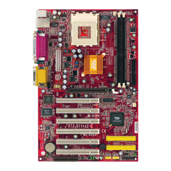
Page 11: Mainboard Layout
KT3 Ultra2-C ATX Mainboard Mainboard Layout Top : mouse CFAN1 Bottom: keyboard SOCKET 462 T:LAN jack (Optional) B:USB ports Top : Parallel Port Bottom: COM A COM B KT333 Top : Game port Bottom: JPW1 Line-Out Line-In AGP Slot PCI Slot 1 BIOS SFAN1 PCI Slot 2... -
Page 12: Msi Special Features
Getting Started MSI Special Features PC Alert™ III The PC Alert III is a utility you can find in the CD-ROM disk. The utility is just like your PC doctor that can de- tect the following PC hardware status during real time operation: monitor CPU &... -
Page 13: Live Bios™/Live Driver
Web site. To use the function, you need to install the “MSI Live Update Series 2” application. After the installation, the “MSI Live Update Series 2” icon (as shown on the right) will appear on the screen. Double click the “MSI Live Update Series 2” icon, and the following screen will appear: Five buttons are placed on the leftmost pane of the screen. -
Page 14: Live Monitor
Live Monitor™ The Live Monitor™ is a tool used to schedule the search for the latest BIOS/drivers version on the MSI Web site. To use the function, you need to install the “MSI Live Update Series 2” application. After the installation, the “MSI Live Monitor” icon (as shown on the right) will appear on the screen. -
Page 15: D-Bracket™ 2 (Optional)
KT3 Ultra2-C ATX Mainboard D-Bracket™ 2 (Optional) D-Bracket™ 2 is an external USB bracket integrating four Diagnostic LEDs, which use graphic signal display to help users understand their system. The LEDs provide up to 16 combinations of signals to debug the system. The 4 LEDs can debug all problems that fail the system, such as VGA, RAM or other failures. - Page 16 Getting Started D-Bracket Description Processor Initialization - This will show information regarding the processor (like brand name, system bus, etc…) Testing RTC (Real Time Clock) Initializing Video Interface - This will start detecting CPU clock, checking type of video onboard. Then, detect and initialize the video adapter. BIOS Sign On - This will start showing information about logo, processor brand name, etc….
-
Page 17: Fuzzy Logic™ 4
After rebooting, click Turbo to apply the test result. Click Default to restore the default values. Features: MSI Logo links to the MSI Web site CPU Speed allows users to adjust the CPU speed through CPU Multiplier and FSB... -
Page 18: Cpu Thermal Protection
Getting Started CPU Thermal Protection Aimed to prevent the CPU from overheating, MSI has developed a CPU Thermal Protection mechanism for AMD Athlon™ XP CPU platform. This CPU Thermal Protection mechanism works on a thermal signal sensor. If the mechanism senses an abnormal temperature rise, it will automatically shut down the system and the CPU temperature will then drop down and resume normal. -
Page 19: Chapter 2. Hardware Setup
Hardware Setup Chapter 2. Hardware Setup Hardware Setup This chapter tells you how to install the CPU, memory modules, and expansion cards, as well as how to setup the jump- ers on the mainboard. Also, it provides the instructions on con- necting the peripheral devices, such the mouse, keyboard, etc. -
Page 20: Quick Components Guide
KT3 Ultra2-C ATX Mainboard Quick Components Guide CFAN1, p.2-16 CPU, p.2-4 DDR DIMMs, p.2-6 Back Panel I/O, p.2-9 JWR1, p.2-8 FDD1, p.2-14 J10, p.2-17 J3, p.2-18 AGP Slot, p.2-27 JPW1, p.2-8 SFAN1, p.2-16 SW3, p.2-26 PCI Slots, p.2-27 JIR1, p.2-18 JGS1, p.2-21 JSP1, p.2-17 IDE1... -
Page 21: Central Processing Unit: Cpu
Hold the CPU down firmly, Lever and then close the lever to complete the installation. MSI Reminds You... Overheating will seriously damage the CPU and system, al- ways make sure the cooling fan can work properly to protect the CPU from overheating. -
Page 22: Thermal Issue For Cpu
KT3 Ultra2-C ATX Mainboard Thermal Issue for CPU WARNING! As processor technology pushes to faster speeds and higher performance, ther- mal management becomes increasingly crucial when building computer systems. Maintaining the proper thermal environment is key to reliable operation. As such, the processor must be maintained in the specified thermal requirements. -
Page 23: Cpu Core Speed Derivation Procedure
BIOS setup utility. To set the clock frequency for the installed CPU, refer to Frequency/ Voltage Control in Chapter 3. BIOS Setup. MSI Reminds You... Replacing CPU While replacing the CPU, always turn off the ATX power sup- ply or unplug the power supply’s power cord from grounded... -
Page 24: Memory
KT3 Ultra2-C ATX Mainboard Memory The mainboard provides 2 slots for 184-pin DDR SDRAM DIMM (Double In-Line Memory Module) modules and supports the memory size up to 2GB. You can install PC2700/DDR333, PC2100/DDR266 or PC1600/ DDR200 modules on the DDR DIMM slots (DDR 1~2). DDR DIMM Slots (DDR 1~2) Introduction to DDR SDRAM... -
Page 25: Dimm Module Combination
2. Insert the DIMM memory module vertically into the DIMM slot. Then push it in until the golden finger on the memory module is deeply in- serted in the socket. MSI Reminds You... You can barely see the golden finger if the module is properly inserted in the socket. -
Page 26: Power Supply
KT3 Ultra2-C ATX Mainboard Power Supply The mainboard supports ATX power supply for the power system. Be- fore inserting the power supply connector, always make sure that all compo- nents are installed properly to ensure that no damage will be caused. ATX 20-Pin Power Connector: JWR1 This connector allows you to connect to an ATX power supply. -
Page 27: Back Panel
Hardware Setup Back Panel The back panel provides the following connectors: Midi/Joystick (Optional) Parallel Mouse Keyboard COM A COM B L-out L-in MIC Mouse Connector ® The mainboard provides a standard PS/2 mouse mini DIN connector for attaching a PS/2 ®... -
Page 28: Keyboard Connector
KT3 Ultra2-C ATX Mainboard Keyboard Connector ® The mainboard provides a standard PS/2 keyboard mini DIN connec- ® ® tor for attaching a PS/2 keyboard. You can plug a PS/2 keyboard directly into this connector. Pin Definition SIGNAL DESCRIPTION Keyboard DATA Keyboard DATA No connection Ground... -
Page 29: Serial Port Connectors: Com A & Com B
Hardware Setup Serial Port Connectors: COM A & COM B The mainboard offers two 9-pin male DIN connectors as serial port COM A & COM B. The ports are 16550A high speed communication ports that send/receive 16 bytes FIFOs. You can attach a serial mouse or other serial devices directly to the connectors. -
Page 30: Parallel Port Connector: Lpt1
KT3 Ultra2-C ATX Mainboard Parallel Port Connector: LPT1 The mainboard provides a 25-pin female centronic connector as LPT. A parallel port is a standard printer port that supports Enhanced Parallel Port (EPP) and Extended Capabilities Parallel Port (ECP) mode. Pin Definition SIGNAL DESCRIPTION STROBE... -
Page 31: Joystick/Midi Connector
1/8” Stereo Audio Connectors Line Out Line In MSI Reminds You... For advanced audio application, RealTek ALC650 audio chip is provided to offer support for 6-channel audio operation and can turn rear audio connectors from 2-channel to 4-/6-channel audio. -
Page 32: Connectors
KT3 Ultra2-C ATX Mainboard Connectors The mainboard provides connectors to connect to FDD, IDE HDD, case, modem, LAN, USB Ports, IR module and CPU/System/Power Supply FAN. Floppy Disk Drive Connector: FDD1 The mainboard provides a standard floppy disk drive connector that supports 360K, 720K, 1.2M, 1.44M and 2.88M floppy disk types. -
Page 33: Ata133 Hard Disk Connectors: Ide1 & Ide2
IDE2 (Secondary IDE Connector) IDE2 can also connect a Master and a Slave drive. MSI Reminds You... If you install two hard disks on cable, you must configure the second drive to Slave mode by setting its jumper. Refer to the hard disk documentation supplied by hard disk vendors for jumper setting instructions. -
Page 34: Fan Power Connectors: Cfan1/Sfan1
CFAN1 SENSOR +12V SFAN1 MSI Reminds You... 1. Always consult the vendors for proper CPU cooling fan. 2. CPUFAN supports the fan control. You can install the PC Alert utility that will automatically control the CPU fan speed according to the actual CPU temperature. -
Page 35: Cd-In Connector: J10
Hardware Setup CD-In Connector: J10 The connector is for CD-ROM audio connector. SPDIF Connector: JSP1 (Optional) The connector is used to connect SPDIF (Sony & Philips Digital Inter- connect Format) interface for digital audio transmission. JSP1 JSP1 Pin Definition SIGNAL Connected to JSP1 SPDIF SPDIF Bracket... -
Page 36: Irda Infrared Module Header: Jir1
KT3 Ultra2-C ATX Mainboard IrDA Infrared Module Header: JIR1 The connector allows you to connect to IrDA Infrared module. You must configure the setting through the BIOS setup to use the IR function. ® JIR1 is compliant with Intel Front Panel I/O Connectivity Design Guide. JIR1 JIR1 Pin Definition Signal... -
Page 37: Front Panel Connectors: Jfp1 & Jfp2
Hardware Setup Front Panel Connectors: JFP1 & JFP2 The mainboard provides two front panel connectors for electrical con- nection to the front panel switches and LEDs. JFP1 is compliant with Intel ® Front Panel I/O Connectivity Design Guide. Power Power Switch JFP1 Reset... -
Page 38: Front Panel Audio Connector: Jaud1
Left channel audio signal to front panel AUD_RET_L Left channel audio signal return from front panel MSI Reminds You... If you don’t want to connect to the front audio header, pins 5 & 6, 9 & 10 have to be jumpered in order to have signal output directed to the rear audio ports. -
Page 39: Power Saving Switch Connector: Jgs1
5VDUAL 3VDUAL D+ (USB signal) D- (USB signal) MSI Reminds You... Because the bluetooth connector shares the USB interface with blue-colored USB2.0 connector, the bottommost USB2.0 port will not function when you attach a bluetooth module to this connector. 2-21... -
Page 40: Front Usb Connectors: Jusb2/Jusb3
KT3 Ultra2-C ATX Mainboard Front USB Connectors: JUSB2/JUSB3 The mainboard provides two USB 2.0 pin headers JUSB2 & JUSB3 ® (optional USB 2.0 bracket available) that are compliant with Intel I/O Con- nectivity Design Guide. USB 2.0 technology increases data transfer rate up to a maximum throughput of 480Mbps, which is 40 times faster than USB 1.1, and is ideal for connecting high-speed USB interface peripherals such as USB HDD, digital cameras, MP3 players, printers, modems and the like. - Page 41 Hardware Setup To Attach the Optional USB 2.0 Ports: 1. Take out the USB2.0 Bracket and D-Bracket™ 2 (optional accessories upon request). 2. Locate the blue USB pinheader (JUSB2) and yellow USB pinheader (JUSB3) on the motherboard. 3. Connect the USB 2.0 bracket to the blue JUSB2 pinheader, and D-Bracket™ 2 to the yellow JUSB3 pinheader.
-
Page 42: D-Bracket™ 2 Connector: Jled
KT3 Ultra2-C ATX Mainboard D-Bracket™ 2 Connector: JLED The mainboard comes with a JLED connector for you to connect to D- Bracket™ 2. D-Bracket™ 2 is a USB Bracket that supports both USB1.1 & 2. 0 spec. It integrates four LEDs and allows users to identify system problem through 16 various combinations of LED signals. -
Page 43: Jumpers
JBAT1 Keep Data Clear Data MSI Reminds You... You can clear CMOS by shorting 2-3 pin while the system is off. Then return to 1-2 pin position. Avoid clearing the CMOS while the system is on; it will damage the mainboard. -
Page 44: Fsb Clock Override Jumper: Sw3
KT3 Ultra2-C ATX Mainboard FSB Clock Override Jumper: SW3 This jumper provides 100MHz and 133MHz Front Side Bus frequency selection. Changing the PSB (Processor System Bus) speed using this jumper may result in unsupported timing configurations. Please make sure the BIOS timings are configured properly for the processor speed. -
Page 45: Slots
Hardware Setup Slots The motherboard provides one AGP slot, six 32-bit PCI bus slots, and one CNR slot. AGP Slot PCI Slots CNR Slot AGP (Accelerated Graphics Port) Slot The AGP slot allows you to insert the AGP graphics card. AGP is an interface specification designed for the throughput demands of 3D graphics. -
Page 46: Pci Interrupt Request Routing
KT3 Ultra2-C ATX Mainboard PCI Interrupt Request Routing The IRQ, acronym of interrupt request line and pronounced I-R-Q, are hardware lines over which devices can send interrupt signals to the microprocessor. The PCI IRQ pins are typically connected to the PCI bus INT A# ~ INT D# pins as follows: Order 1 Order 2... -
Page 47: Chapter 3. Bios Setup
BIOS Setup Chapter 3. BIOS Setup BIOS Setup This chapter provides information on the BIOS Setup program and allows you to configure the system for optimum use. You may need to run the Setup program when: An error message appears on the screen during the system booting up, and requests you to run SETUP. -
Page 48: Entering Setup
KT3 Ultra2-C ATX Mainboard Entering Setup Power on the computer and the system will start POST (Power On Self Test) process. When the message below appears on the screen, press <DEL> key to enter Setup. DEL:Setup F11:Boot Menu F12:Network boot TAB:Logo If the message disappears before you respond and you still wish to enter Setup, restart the system by turning it OFF and On or pressing the RESET... -
Page 49: Control Keys
BIOS Setup Control Keys <↑> Move to the previous item <↓> Move to the next item <←> Move to the item in the left hand Move to the item in the right hand <→> <Enter> Select the item <Esc> Jumps to the Exit menu or returns to the main menu from a submenu <+/PU>... -
Page 50: The Main Menu
KT3 Ultra2-C ATX Mainboard The Main Menu Once you enter AMIBIOS NEW SETUP UTILITY, the Main Menu will ap- pear on the screen. The Main Menu displays twelve configurable functions and two exit choices. Use arrow keys to move among the items and press <Enter>... - Page 51 BIOS Setup Integrated Peripherals Use this menu to specify your settings for integrated peripherals. PC Health Status This entry shows your PC health status. Frequency/Voltage Control Use this menu to specify your settings for frequency/voltage control. Set Supervisor Password Use this menu to set Supervisor Password. Set User Password Use this menu to set User Password.
-
Page 52: Standard Cmos Features
KT3 Ultra2-C ATX Mainboard Standard CMOS Features The items inside STANDARD CMOS SETUP menu are divided into 9 categories. Each category includes none, one or more setup items. Use the arrow keys to highlight the item you want to modify and use the <PgUp> or <PgDn>... - Page 53 When Enabled, BIOS will issue a virus warning message and beep if a write to the boot sector or the partition table of the HDD is attempted. Setting options: Disabled and Enabled. MSI Reminds You... This feature only protects the boot sector, not the whole hard disk.
-
Page 54: Advanced Bios Features
KT3 Ultra2-C ATX Mainboard Advanced BIOS Features Quick Boot Setting the item to Enabled allows the system to boot within 5 seconds since it will skip some check items. Available options: Enabled, Disabled. Full Screen Logo Show This item enables you to show the company logo on the bootup screen. Set- tings are: Enabled Shows a still image (logo) on the full screen at boot. - Page 55 Disabled Disable this sequence. MSI Reminds You... Available settings for “1st/2nd/3rd Boot Device” vary depend- ing on the bootable devices you have installed. For example, if you did not install a floppy drive, the setting “Floppy” does not...
- Page 56 KT3 Ultra2-C ATX Mainboard Try Other Boot Devices Setting the option to Yes allows the system to try to boot from other devices if the system fails to boot from the 1st/2nd/3rd boot device. S.M.A.R.T. for Hard Disks This allows you to activate the S.M.A.R.T. (Self-Monitoring Analysis & Re- porting Technology) capability for the hard disks.
- Page 57 BIOS Setup Boot To OS/2 ® This allows you to run the OS/2 operating system with DRAM larger than ® 64MB. When you choose No, you cannot run the OS/2 operating system with DRAM larger than 64MB. But it is possible if you choose Yes. Internal Cache Cache memory is additional memory that is much faster than conventional DRAM (system memory).
- Page 58 KT3 Ultra2-C ATX Mainboard MPS Table Version This field allows you to select which MPS (Multi-Processor Specification) version to be used for the operating system. You need to select the MPS ver- sion supported by your operating system. To find out which version to use, consult the vendor of your operating system.
-
Page 59: Advanced Chipset Features
BIOS Setup Advanced Chipset Features MSI Reminds You... Change these settings only if you are familiar with the chipset. DRAM Timing Control Press <Enter> and the following sub-menu appears. Current Host Clock This item shows the current CPU frequency. 3-13... - Page 60 KT3 Ultra2-C ATX Mainboard Configure SDRAM Timing by Selects whether DRAM timing is controlled by the SPD (Serial Presence Detect) EEPROM on the DRAM module. Setting to SPD enables SDRAM Frequency, SDRAM CAS# Latency, Row Precharge Time, RAS Pulse Width, RAS to CAS Delay and SDRAM Bank Interleave auto- matically to be determined by BIOS based on the configurations on the SPD.
- Page 61 BIOS Setup SDRAM Bank Interleave This field selects 2-bank or 4-bank interleave for the installed SDRAM. Disable the function if 16MB SDRAM is installed. Settings: Disabled, 2-Way and 4-Way. SDRAM Burst Length This setting allows you to set the size of Burst-Length for DRAM. Bursting feature is a technique that DRAM itself predicts the address of the next memory location to be accessed after the first address is accessed.
- Page 62 KT3 Ultra2-C ATX Mainboard AGP Mode The item sets an appropriate mode for the installed AGP card. Setting options: 1x, 2x, 4x, Auto. Select 4x only if your AGP card supports it. AGP Comp. Driving This field is used to adjust the AGP driving force. Selecting Manual allows you to select an AGP driving force in Manual AGP Comp.
- Page 63 BIOS Setup PCI Delay Transaction The chipset has an embedded 32-bit posted write buffer to support delayed transactions cycles so that transactions to and from the ISA bus are buffered and PCI bus can perform other transactions while the ISA transaction is underway.
-
Page 64: Power Management Features
KT3 Ultra2-C ATX Mainboard Power Management Features MSI Reminds You... S3-related functions described in this section are available only when your BIOS supports S3 sleep mode. IPCA Function This item is to activate the ACPI (Advanced Configuration and Power Man- agement Interface) function. - Page 65 BIOS Setup to restore the system when a “wake up” event occurs. Auto BIOS determines the best mode automatically. Call VGA at S3 Resuming Selecting Enabled allows BIOS to call VGA BIOS to initialize the VGA card when system wakes up (resumes) from S3 sleep state. The system resume time is shortened when you disable the function, but system will need an AGP driver to initialize the VGA card.
- Page 66 KT3 Ultra2-C ATX Mainboard CPU Critical Temperature If the CPU temperature reaches the upper limit preset in this setting, the warn- ing mechanism will be activated. This helps you to prevent the CPU overheat- ing problem. Power Button Function This feature sets the function of the power button. Settings are: On/Off The power button functions as normal power off button.
- Page 67 Settings: Enabled, Disabled. MSI Reminds You... 1. You need to install a modem card supporting power on func- tion for “Wake Up On Ring” function.
-
Page 68: Pnp/Pci Configurations
KT3 Ultra2-C ATX Mainboard PNP/PCI Configurations This section describes configuring the PCI bus system and PnP (Plug & Play) feature. PCI, or Peripheral Component Interconnect, is a system which al- lows I/O devices to operate at speeds nearing the speed the CPU itself uses when communicating with its special components. - Page 69 BIOS Setup PCI Latency Timer This item controls how long each PCI device can hold the bus before another takes over. When set to higher values, every PCI device can conduct transac- tions for a longer time and thus improve the effective PCI bandwidth. For better PCI performance, you should set the item to higher values.
-
Page 70: Integrated Peripherals
KT3 Ultra2-C ATX Mainboard Integrated Peripherals FDC Function This is used to enable or disable the onboard Floppy controller. Option Description Auto BIOS will automatically determine whether to enable the onboard Floppy controller or not. Enabled Enables the onboard Floppy controller. Disabled Disables the onboard Floppy controller. - Page 71 BIOS Setup Serial Port2 Mode This item sets the operation mode for Serial Port 2. Settings: Normal, 1.6uS, 3/16 Baud and ASKIR (the last three operation modes are setting options for IR function). IR Pin Select Set to IRRX/IRTX when using an internal IR module connected to the IR header.
- Page 72 KT3 Ultra2-C ATX Mainboard OnBoard IDE This setting controls the onboard IDE controller. Setting options: Disabled, Primary, Secondary, Both. OnBoard LAN This setting disables/enables the onboard LAN controller. Setting options: Disabled, Enabled. OnBoard LAN P.M.E. This setting determines whether the activity of P.M.E. (Power Manage- ment Event) will activate the onboard LAN controller.
-
Page 73: Pc Health Status
BIOS Setup PC Health Status This section shows the status of your CPU, fan, overall system status, etc. Monitor function is available only if there is hardware monitoring mechanism onboard. Chassis Intrusion The field enables or disables the feature of recording the chassis intrusion status and issuing a warning message if the chassis is once opened. -
Page 74: Frequency/Voltage Control
KT3 Ultra2-C ATX Mainboard Frequency/Voltage Control Use this menu to specify your settings for frequency/voltage control. Spread Spectrum When the motherboard’s clock generator pulses, the extreme values (spikes) of the pulses creates EMI (Electromagnetic Interference). The Spread Spec- trum function reduces the EMI generated by modulating the pulses so that the spikes of the pulses are reduced to flatter curves. - Page 75 BIOS Setup voltage (Vcore). These settings offer users a tool to overclock the system. MSI Reminds You... Changing CPU Ratio/Vcore could result in the instability of the system; therefore, it is NOT recommended to change the default setting for long-term usage.
-
Page 76: Set Supervisor/User Password
BIOS FEATURES menu. If the PASSWORD CHECK option is set to Always, the password is required both at boot and at entry to Setup. If set to Setup, password prompt only occurs when you try to enter Setup. MSI Reminds You... About Supervisor Password & User Password: Supervisor password: Can enter and change the settings of the setup menu. -
Page 77: Load High Performance/Bios Setup Defaults
Pressing ‘Enter’ loads the default BIOS values that enable the best system performance but may lead to a stability issue. MSI Reminds You... The option is for power or overclocking users only. Use of high performance defaults will tighten most timings to increase the system performance. -
Page 78: Appendix: Using 4- Or 6-Channel Audio Function
Using 4- or 6-Channel Audio Function Appendix: Using 4- or 6-Channel Audio Function The motherboard is equipped with Realtek ALC650 chip, which provides support for 6-channel audio output, including 2 Front, 2 Rear, 1 Center and 1 Subwoofer channel. ALC650 allows the board to attach 4 or 6 speakers for better surround sound effect. -
Page 79: Installing The Audio Driver
KT3 Ultra2-C ATX Mainboard Installing the Audio Driver You need to install the driver for Realtek ALC650 chip to function prop- erly before you can get access to 4-/6-channel audio operations. Follow the procedures described below to install the drivers for different operating systems. Installation for Windows 98SE/ME/2000/XP For Windows ®... -
Page 80: Using 4- Or 6-Channel Audio Function
Using 4- or 6-Channel Audio Function Click here Click Finish to restart the system. Select this option Click here... -
Page 81: Attaching Speakers
2-, 4- and 6-channel using back panel connec- tors are described on the next page MSI Reminds You... If the Center and Subwoofer speaker exchange their audio chan- nels when you play video or music on the computer, a converter may be required to exchange center and subwoofer audio signals. - Page 82 Using 4- or 6-Channel Audio Function 2-Channel Analog Audio Output Line Out (Front channels) Line In Description: Line Out, Line In and MIC functions all exist under 2-channel configuration. 4-Channel Analog Audio Output Line Out (Front channels) Line Out (Rear channels) Description: Line In is converted to Line Out function under 4-channel configuration.
-
Page 83: Selecting 4- Or 6-Channel Setting
KT3 Ultra2-C ATX Mainboard Selecting 4- or 6-Channel Setting Click the audio icon from the window tray at the bottom of the screen. Select any surround sound effect you prefer from the “Environment” pull-down menu under the Sound Effect tab. Click here and the pull- down menu will appear Click the Speaker Configuration tab. - Page 84 Using 4- or 6-Channel Audio Function The following window appears. Select the multi-channel operation you prefer from No. of Speakers. Click OK.
-
Page 85: Testing The Connected Speakers
Rear Left Center Select the speaker which you want to test by clicking on it. MSI Reminds You... 6 speakers appear on the “Speaker Test” window only when you select “6 channels mode” in the “No. of Speakers” column. If you select “4 channels mode”, only 4 speakers appear on the... -
Page 86: Playing Karaok
Using 4- or 6-Channel Audio Function Playing KaraOK The KaraOK function will automatically remove human voice (lyrics) and leave melody for you to sing the song. The function is applied only for 2-channel audio operation, so make sure “2 channels mode” is selected in the “No. -
Page 87: Troubleshooting
Q: How do I know what MSI D-LED or D-bracket light mean? A: Please follow the special tech issue, http://www.msi.com.tw/support/ techexpress/special_tech/smartled.htm Q: I have got MSI Motherboard and when it says detecting drives, it detects them but says an error saying "Primary IDE Channel no 80 Conductor Cable Installed"... - Page 88 A: Please refer to the following suggestions: 1. Try the BIOS boot recovery feature as described in http://www.msi.com.tw/support/bios/boot.htm 2. Try to clear the CMOS If problem still persists, ask your reseller for new BIOS chip or contact one of MSI office near your place for new BIOS chip http:// www.msi.com.tw/contact/main.htm...
- Page 89 BIOS, unless you really have to. Q: How do I update the BIOS? A: Please refer to http://www.msi.com.tw/support/bios/note.htm for details. Q: How do I identify the BIOS version? A: Upon boot-up, the 1st line appearing after the memory count is the BIOS version.
- Page 90 KT3 Ultra2-C ATX Mainboard 6th - 7th digit refers to the customer as MS = all standard customers. V1.0 refers to the BIOS version. 091096 refers to the date this BIOS is released. Q: After flashing the bios and rebooting the system, the screen went blank. A: For AMI BIOS Rename the desired AMI BIOS file to AMIBOOT.ROM and save it on a floppy disk.
-
Page 91: Glossary
Glossary Glossary Glossary ACPI (Advanced Configuration & Power Interface) This power management specification enables the OS (operating system) to control the amount of power given to each device attached to the computer. Windows 98/98SE, Windows 2000 and Windows ME can fully support ACPI to allow users managing the system power flexibly. - Page 92 KT3 Ultra2-C ATX Mainboard contents of frequently accessed RAM locations and the addresses where these data items are stored. Chipset A collection of integrated chips designed to perform one or more related functions. For example, a modem chipset contains all the primary circuits for transmitting and receiv- ing data;...
- Page 93 Glossary ECC Memory (Error Correcting Code Memory) A type of memory that contains special circuitry for testing the accuracy of data and correcting the errors on the fly. EEPROM Acronym for Electrically Erasable Programmable Read-Only Memory. An EEPROM is a special type of PROM that can be erased by exposing it to an electrical charge. Like other types of PROM, EEPROM retains its contents even when the power is turned off.
- Page 94 KT3 Ultra2-C ATX Mainboard IDE (Integrated Drive Electronics) A type of disk-drive interface widely used to connect hard disks, CD-ROMs and tape drives to a PC, in which the controller electronics is integrated into the drive itself, eliminating the need for a separate adapter card. The IDE interface is known as the ATA (AT Attachment) specification.
- Page 95 Glossary LBA (Logical Block Addressing) Logical block addressing is a technique that allows a computer to address a hard disk larger than 528 megabytes. A logical block address is a 28-bit value that maps to a specific cylinder-head-sector address on the disk. 28 bits allows sufficient variation to specify addresses on a hard disk up to 8.4 gigabytes in data storage capacity.
- Page 96 KT3 Ultra2-C ATX Mainboard PS/2 Port A type of port developed by IBM for connecting a mouse or keyboard to a PC. The PS/2 port supports a mini DIN plug containing just 6 pins. Most modern PCs equipped with PS/2 ports so that the special port can be used by another device, such as a modem.
Need help?
Do you have a question about the KT3 Ultra2-C MS-6593 and is the answer not in the manual?
Questions and answers