Table of Contents
Advertisement
Quick Links
www.ti.com
EVM User's Guide: TAA3040
TAA3040EVM-PDK Evaluation Module
1 Description
This user's guide describes the function and use
of the TAA3040EVM-PDK. This document includes
the hardware configuration instructions, a quick-start
guide, jumper and connector descriptions, software
description, schematics, and printed circuit board
(PCB) layout that demonstrate TI's recommended
practices for these devices.
1 Description..............................................................................................................................................................................
2
Features...................................................................................................................................................................................1
3
Trademarks..............................................................................................................................................................................2
4 Evaluation Module Overview.................................................................................................................................................
4.1 Introduction........................................................................................................................................................................
Contents........................................................................................................................................................................3
4.3 Specifications.....................................................................................................................................................................
4.4 Device Information.............................................................................................................................................................
5 Hardware Overview................................................................................................................................................................
Settings..................................................................................................................................................................4
Overview................................................................................................................................................................13
Installation.......................................................................................................................................13
6.2 TAA3040EVM GUI Installation.........................................................................................................................................
Start.............................................................................................................................................................................16
7.2 Ready for Use..................................................................................................................................................................
SBAU474 - DECEMBER 2024
Submit Document Feedback
TAA3040EVM-PDK
Table of Contents
Settings............................................................................................................................10
2
S Output........................................................................................................
Copyright © 2024 Texas Instruments Incorporated
2 Features
•
Complete evaluation kit for the TAA3040 quad-
channel ADC.
•
Low-cost stereo ADC dynamic range of 104dB
•
On-board microphones provided for voice
recording testing
•
Direct access to digital audio signals and control
interface for simple end-system integration
•
USB connection to PC provides power, control,
and streaming audio data for easy evaluation
TAA3040EVM-PDK Evaluation Module
Description
1
2
3
3
3
4
14
18
19
1
Advertisement
Table of Contents

Related Manuals for Texas Instruments TAA3040


Summary of Contents for Texas Instruments TAA3040
-
Page 1: Table Of Contents
TAA3040EVM-PDK Evaluation Module 1 Description 2 Features This user's guide describes the function and use • Complete evaluation kit for the TAA3040 quad- of the TAA3040EVM-PDK. This document includes channel ADC. the hardware configuration instructions, a quick-start • Low-cost stereo ADC dynamic range of 104dB guide, jumper and connector descriptions, software •... -
Page 2: Trademarks
Table 9-1. TAA3040EVM-K Bill of Materials..........................23 Table 9-2. AC-MB Bill of Materials............................. 3 Trademarks PurePath ™ is a trademark of Texas Instruments. Audio Toolbox ™ is a trademark of MathWorks. All trademarks are the property of their respective owners. 4 Evaluation Module Overview TAA3040EVM-PDK Evaluation Module SBAU474 –... -
Page 3: Introduction
Evaluation Module Overview 4.1 Introduction The TAA3040EVM-K is an evaluation module (EVM) designed to demonstrate the performance and functionality of the TAA3040 family of devices. This family includes the devices shown in Table 4-1 with differences in performance and function noted. -
Page 4: Hardware Overview
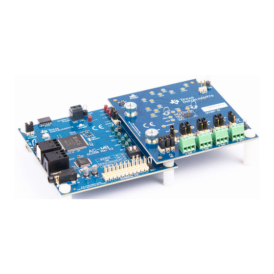
The evaluation kit consists of the TAA3040EVB daughterboard and the AC-MB motherboard. The motherboard is used to provide power, control, and digital audio signals to the evaluation module. The daughterboard contains the TAA3040 device and its input connections. A detailed functional overview of the TAA3040EVB system is described in Section 5.1 AC-MB Settings... -
Page 5: Figure 5-2. Ac-Mb Usb Audio Setting
The AC-MB is detected by the OS as an audio device with the name TI USB Audio UAC2.0. Figure 5-2 shows the AC-MB audio setting for the USB mode of operation. Figure 5-2. AC-MB USB Audio Setting SBAU474 – DECEMBER 2024 TAA3040EVM-PDK Evaluation Module Submit Document Feedback Copyright © 2024 Texas Instruments Incorporated... -
Page 6: Figure 5-3. Ac-Mb Optical Or Auxiliary Analog Audio Setting
This feature can be useful when a digital input DAC is connected to the AC-MB, providing an analog input for quick evaluation. In Auxiliary Analog Audio mode the audio serial interface format is fixed to a 24-bit, 48-kHz, I mode. TAA3040EVM-PDK Evaluation Module SBAU474 – DECEMBER 2024 Submit Document Feedback Copyright © 2024 Texas Instruments Incorporated... -
Page 7: Figure 5-4. Ac-Mb External Audio Setting
USB interface and PCM9211 are isolated with this setting. Figure 5-4 shows the AC-MB audio setting for the external mode of operation. Figure 5-4. AC-MB External Audio Setting SBAU474 – DECEMBER 2024 TAA3040EVM-PDK Evaluation Module Submit Document Feedback Copyright © 2024 Texas Instruments Incorporated... -
Page 8: Figure 5-5. Ac-Mb Connection With External Audio Serial
Host Processor / Audio Analyzer Figure 5-5. AC-MB Connection with External Audio Serial Interface TAA3040EVM-PDK Evaluation Module SBAU474 – DECEMBER 2024 Submit Document Feedback Copyright © 2024 Texas Instruments Incorporated... -
Page 9: Figure 5-6. Power-Supply Distribution Of The Ac-Mb
POWER LED (D3) turns ON. The USB READY LED indicates that a successful USB communication is established between the AC-MB and the host computer. SBAU474 – DECEMBER 2024 TAA3040EVM-PDK Evaluation Module Submit Document Feedback Copyright © 2024 Texas Instruments Incorporated... -
Page 10: Taa3040Evm-Pdk Hardware Settings
The different operation modes are highlighted in this section. The INxP and INxM pins of the TAA3040 can optionally connect to an onboard microphone for quick evaluation, and can be optionally configured to bypass the input decoupling capacitors for evaluating the functionality of the digital microphones or GPIOs. -
Page 11: Figure 5-8. Taa3040Evb Connection For Line Input Application
For the line input configuration (shown in Figure 5-8), the TAA3040 captures the audio signal provided through terminals J2 (IN1), J3 (IN2), J4 (IN3), and J5 (IN4). The input accepted in this mode is a differential, 2-VRMS, full-scale audio signal. If a single-ended source is used, the 1-VRMS signal is supported. -
Page 12: Figure 5-9. Taa3040Evb Connection For The Onboard Microphone Test
For the onboard microphone input configuration (shown in Figure 5-9), the TAA3040 records the audio captured from the microphones located on the bottom edge of the board. MICBIAS is used to power the onboard microphone, so header J14 must be shorted. There must not be any connections to J1 during onboard microphone use to preserve the performance of the microphone. -
Page 13: Software Overview
PPC3 installation. Figure 6-1. PurePath Console 3 Installation Open the PPC3 installer and follow the instructions in the setup wizard. SBAU474 – DECEMBER 2024 TAA3040EVM-PDK Evaluation Module Submit Document Feedback Copyright © 2024 Texas Instruments Incorporated... -
Page 14: Taa3040Evm Gui Installation
Click on the TAA3040 app title. Figure 6-2. PurePath Console 3 App Center The TAA3040 GUI is designed to work with up to four devices at any time. As shown in Figure 6-3, choose the 1 device radial button and click New. -
Page 15: Figure 6-4. Audio Config Tab
Before changing any parameters, check the lower left corner of the PPC3 window, as shown in Figure 6-5, to verify that the EVM is connected. If no EVM is detected, the text will read TAA3040 offline. If the EVM is detected, a Connect button appears. Clicking this button connects the hardware. Figure 6-5. Hardware Connect When the hardware is connected, the Connect button changes to read Disconnect, and the device is ready to be configured. -
Page 16: Quick Start
Figure 7-2. MIC Bias Configuration The default state for the TAA3040 is standby mode and, with the exception of the channel digital volume, all device configurations must be done in standby mode. The TAA3040 does not provide a digital audio output in standby mode. -
Page 17: Figure 7-4. Disabled Controls In Active Mode
Figure 7-4. Disabled Controls in Active Mode Audio can now be captured on your PC using the audio program of your choice. SBAU474 – DECEMBER 2024 TAA3040EVM-PDK Evaluation Module Submit Document Feedback Copyright © 2024 Texas Instruments Incorporated... -
Page 18: Configuring The Audio Serial Bus For The I
S Output The TAA3040 features a highly flexible audio serial bus that can be configured to implement a wide range of data formats. The default format is TDM, however the GUI can be used to change the data format to I S. -
Page 19: Ready For Use
S mode and the BCLK and FSYNC ratio is fixed at 64. The EVM is now ready for use with the audio recording program of your choice. SBAU474 – DECEMBER 2024 TAA3040EVM-PDK Evaluation Module Submit Document Feedback Copyright © 2024 Texas Instruments Incorporated... -
Page 20: Saving A Configuration
The configuration is saved as a .ppc3 file. To load a saved configuration, click the upper left corner of the PPC3 window and select Open. Navigate to the location of the saved .ppc3 file, and click Open. Figure 7-9. Saving a Configuration in PPC3 TAA3040EVM-PDK Evaluation Module SBAU474 – DECEMBER 2024 Submit Document Feedback Copyright © 2024 Texas Instruments Incorporated... -
Page 21: System Overview
Analog Bypass Input Header PCM9211 Digital On Board On Board Input Interface Selector Microphone Microphone terminals Test Points Connection Headers Figure 8-1. System Overview SBAU474 – DECEMBER 2024 TAA3040EVM-PDK Evaluation Module Submit Document Feedback Copyright © 2024 Texas Instruments Incorporated... -
Page 22: Schematic And Bill Of Materials
To DUT Connector to A C-MB External RST Option EEPROM for Firmw are ID On-Board +3.3V Power Supply Power LED Figure 9-1. ADCx140EVM-PDK Schematics TAA3040EVM-PDK Evaluation Module SBAU474 – DECEMBER 2024 Submit Document Feedback Copyright © 2024 Texas Instruments Incorporated... -
Page 23: Table 9-1. Taa3040Evm-K Bill Of Materials
TP1, TP2, TP3, Test Point, Miniature, Red, TH Red Miniature 5000 Keystone TP4, TP5, TP6, Testpoint TP7, TP8, TP11, TP12, TP13, TP14, TP15, TP16, TP17, TP18 SBAU474 – DECEMBER 2024 TAA3040EVM-PDK Evaluation Module Submit Document Feedback Copyright © 2024 Texas Instruments Incorporated... - Page 24 Part Number Manufacturer TP19, TP20, TP21, Test Point, Miniature, Green, TH Green Miniature 5116 Keystone TP22, TP23, TP24, Testpoint TP25, TP26, TP27, TP28, TP29, TP30 TAA3040EVM-PDK Evaluation Module SBAU474 – DECEMBER 2024 Submit Document Feedback Copyright © 2024 Texas Instruments Incorporated...
-
Page 25: Ac-Mb Schematic And Bill Of Materials
EVM-SPI-MOSI 0.1uF 0.1uF 0.1uF 0.1uF 0.1uF 0.1uF 0.1uF 0.1uF EVM-SPI-SS0 EVM-SPI-SS1 I²C Power Control Interface Translation Test Points EVM Connector Figure 9-2. AC-MB Schematics SBAU474 – DECEMBER 2024 TAA3040EVM-PDK Evaluation Module Submit Document Feedback Copyright © 2024 Texas Instruments Incorporated... -
Page 26: Table 9-2. Ac-Mb Bill Of Materials
Thumb Nut, M3 x 0.5 Thread, 8mm Head 96115A420 McMaster Carr H7, H8, H9, H10 Standoff, Hex, Male/Female, 4-40, Nylon, Standoff, Hex, 4802 Keystone 1/2" Male/Female, 4-40, Nylon, 1/2" TAA3040EVM-PDK Evaluation Module SBAU474 – DECEMBER 2024 Submit Document Feedback Copyright © 2024 Texas Instruments Incorporated... - Page 27 25.5k RES, 25.5 k, 1%, 0.05 W, 0201 0201 RC0201FR-0725K Yageo America 51.0k RES, 51.0 k, 1%, 0.05 W, 0201 0201 RC0201FR-0751K Yageo America SBAU474 – DECEMBER 2024 TAA3040EVM-PDK Evaluation Module Submit Document Feedback Copyright © 2024 Texas Instruments Incorporated...
- Page 28 Sb/Br) U12, U16, U18, 4-Bit Dual-Supply Bus Transceiver With RSV0016A SN74AVC4T774R Texas Instruments U19, U21, U22 Configurable Voltage-Level Shifting and 3-State Outputs, RSV0016A (UQFN-16) TAA3040EVM-PDK Evaluation Module SBAU474 – DECEMBER 2024 Submit Document Feedback Copyright © 2024 Texas Instruments Incorporated...
-
Page 29: Interface
Test Point, Miniature, Red, TH Red Miniature 5000 Keystone TP15 Testpoint TP3, TP4, TP5, Test Point, Miniature, Green, TH Green Miniature 5116 Keystone TP6, TP11, TP12, Testpoint TP13 SBAU474 – DECEMBER 2024 TAA3040EVM-PDK Evaluation Module Submit Document Feedback Copyright © 2024 Texas Instruments Incorporated... -
Page 30: Matlab Audio Capture Example
'SampleRate', 48000, … 'NumChannels', 8 ,… 'BitDepth', '32-bit float',… 'OutputDataType','double'); elseif ispc % windows driver devoiceReader = audioDeviceReader( 'Driver','ASIO', 'Device', 'Texas Instruments USB Audio ...',… 'SampleRate', 48000, … 'NumChannels', 8 ,… 'BitDepth', '32-bit float',… 'OutputDataType','double’); setup(deviceReader);% Setup the device reader % Play out a file through PC and capture in the EVM info = audioinfo( infile_name );% Read audiophile infile_name... - Page 31 STANDARD TERMS FOR EVALUATION MODULES Delivery: TI delivers TI evaluation boards, kits, or modules, including any accompanying demonstration software, components, and/or documentation which may be provided together or separately (collectively, an “EVM” or “EVMs”) to the User (“User”) in accordance with the terms set forth herein.
- Page 32 www.ti.com Regulatory Notices: 3.1 United States 3.1.1 Notice applicable to EVMs not FCC-Approved: FCC NOTICE: This kit is designed to allow product developers to evaluate electronic components, circuitry, or software associated with the kit to determine whether to incorporate such items in a finished product and software developers to write software applications for use with the end product.
- Page 33 www.ti.com Concernant les EVMs avec antennes détachables Conformément à la réglementation d'Industrie Canada, le présent émetteur radio peut fonctionner avec une antenne d'un type et d'un gain maximal (ou inférieur) approuvé pour l'émetteur par Industrie Canada. Dans le but de réduire les risques de brouillage radioélectrique à...
- Page 34 www.ti.com EVM Use Restrictions and Warnings: 4.1 EVMS ARE NOT FOR USE IN FUNCTIONAL SAFETY AND/OR SAFETY CRITICAL EVALUATIONS, INCLUDING BUT NOT LIMITED TO EVALUATIONS OF LIFE SUPPORT APPLICATIONS. 4.2 User must read and apply the user guide and other available documentation provided by TI regarding the EVM prior to handling or using the EVM, including without limitation any warning or restriction notices.
- Page 35 Notwithstanding the foregoing, any judgment may be enforced in any United States or foreign court, and TI may seek injunctive relief in any United States or foreign court. Mailing Address: Texas Instruments, Post Office Box 655303, Dallas, Texas 75265 Copyright © 2023, Texas Instruments Incorporated...
- Page 36 TI products. TI’s provision of these resources does not expand or otherwise alter TI’s applicable warranties or warranty disclaimers for TI products. TI objects to and rejects any additional or different terms you may have proposed. IMPORTANT NOTICE Mailing Address: Texas Instruments, Post Office Box 655303, Dallas, Texas 75265 Copyright © 2024, Texas Instruments Incorporated...
Need help?
Do you have a question about the TAA3040 and is the answer not in the manual?
Questions and answers