Advertisement
Quick Links
www.ti.com
User's Guide
TAS6424E-Q1 EVM
Gregg Scott
This manual describes the operations of the TAS6424EQ1EVM. The TAS6424EQ1EVM is a stand-alone EVM.
™
The PurePath
Control Console 3 GUI (PPC3) is used to initialize and operate the EVM. The main topics of this
document are:
•
Hardware implementation and descriptions
•
Software implementation and descriptions
•
TAS6424E-Q1 EVM operations (hardware and software)
Required equipment and accessories:
1. TAS6424E-Q1 EVM
2. USB A male to micro B male cable
3. Power Supply Unit (PSU) up to 26.4 V, > 6 A capable, if J12 is removed and 12 V is provided.
If J12 is in, limit the input voltage to 18 V.
4. 1-4 resistive loads or speaker loads
5. 2-6 pair of wires stripped both ends
6. 2-mm slotted screwdriver
7. Optical audio source (optional)
8. Optical SPDIF cable (optional)
9. Desktop or laptop PC with Microsoft
1
Trademarks..............................................................................................................................................................................1
2 Hardware Overview................................................................................................................................................................
Overview..................................................................................................................................................................4
5 Revision History...................................................................................................................................................................
1 Trademarks
PurePath
™
are trademarks of Texas Instruments.
®
Microsoft
and Windows
All trademarks are the property of their respective owners.
SLOU553 - MAY 2021
Submit Document Feedback
®
Windows
Table of Contents
Schematic...............................................................................................................20
List of Tables
®
are registered trademarks of Microsoft Corporation.
Copyright © 2021 Texas Instruments Incorporated
ABSTRACT
®
7 operating system
Table of Contents
2
32
TAS6424E-Q1 EVM
1
Advertisement

Related Manuals for Texas Instruments TAS6424E-Q1


Summary of Contents for Texas Instruments TAS6424E-Q1
-
Page 1: Table Of Contents
Hardware implementation and descriptions • Software implementation and descriptions • TAS6424E-Q1 EVM operations (hardware and software) Required equipment and accessories: 1. TAS6424E-Q1 EVM 2. USB A male to micro B male cable 3. Power Supply Unit (PSU) up to 26.4 V, > 6 A capable, if J12 is removed and 12 V is provided. -
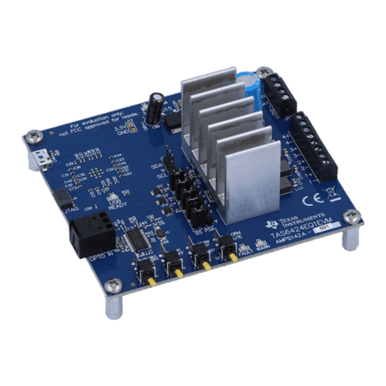
Page 2: Hardware Overview
2 Hardware Overview 2.1 TAS6424E-Q1 Evaluation Module Description The TAS6424E-Q1 EVM is a stand-alone EVM. It has single power supply input, USB control via PurePath Control Console 3 (PPC3) and two digital (I2S) audio input options. See the EVM block diagram in Figure 2-1. - Page 3 Hardware Overview The block diagram shows the TAS6424E-Q1 EVM signal flow. PVDD Input Power 4.5 Vdc to 26.4 Vdc Connector Jumper VBAT 3.3 Vdc LDO 4.5 Vdc to 18Vdc SPDIF Power Switch 3.3 Vdc VBAT PVDD Audio Input SPDIF...
-
Page 4: Software Overview
After login, the user will see this web page with a similar list of software products available for download. Figure 3-1. PPC3 Download Window TAS6424E-Q1 EVM SLOU553 – MAY 2021 Submit Document Feedback Copyright © 2021 Texas Instruments Incorporated... - Page 5 Figure 3-2 is displayed, click on “sign in” to see TAS6424E EVM application. All of the apps shown below may not be displayed for the user. SLOU553 – MAY 2021 TAS6424E-Q1 EVM Submit Document Feedback Copyright © 2021 Texas Instruments Incorporated...
- Page 6 TAS6424E EVM box will appear in “Installed EVM Apps” section, see Figure 3-3. Click on TAS6424E box to launch TAS6424E App. Figure 3-3. Available Apps Window TAS6424E-Q1 EVM SLOU553 – MAY 2021 Submit Document Feedback Copyright © 2021 Texas Instruments Incorporated...
- Page 7 USB is connected to the PC, the Home Window will display “Connect” box in the bottom right hand corner. If the EVM is not powered on or the USB is not connected, only “TAS6424E EVM – Offline” is displayed. Figure 3-4 shows the downloading progress of TAS6424E-Q1 applications. Figure 3-4. PPC3 Window SLOU553 – MAY 2021...
- Page 8 There are three windows available with the TAS6424E EVM PPC3: Home Window, Register Map Window and Device Monitor and Control Window. Figure 3-5. TAS6424E EVM Home Window TAS6424E-Q1 EVM SLOU553 – MAY 2021 Submit Document Feedback Copyright © 2021 Texas Instruments Incorporated...
- Page 9 Console 3 – TAS6424E EVM Register Map Window When click on Register Map Box on the Home Window, the Register Map Window is displayed. The Register Map indicates the current setting of all the registers in TAS6424E-Q1. Figure 3-6. TAS6424E EVM Register Map Window SLOU553 –...
- Page 10 When click on Device Monitor and Control Box on the Home Window, the Device Monitor and Control Window is displayed. Figure 3-7. TAS6424E EVM Device Monitor and Control Window TAS6424E-Q1 EVM SLOU553 – MAY 2021 Submit Document Feedback Copyright © 2021 Texas Instruments Incorporated...
- Page 11 Software Overview 3.5 TAS6424E-Q1 EVM Start Up This section describes the TAS6424E-Q1 start-up procedure. Have the equipment and accessories listed on the first page of this document available. 3.5.1 TAS6424E-Q1 EVM Setup Hardware and software connections: • Desk top or laptop PC running Windows 7. Open PPC3 GUI.
- Page 12 Software Overview www.ti.com 3.5.2 TAS6424E-Q1 Settings on Device Monitor and Control Window The TAS6424E Register Map window is for reference. Most of the register settings are done on the Device Monitor and Control window Click on “CONNECT” button on the bottom left corner of the TAS6424E EVM application window, see Figure 3-9.
- Page 13 To choose a different phase offset, use the pull-down menu on the “Phase” box. There are four gain settings in TAS6424E-Q1: low, normal, high and maximum. The default setting is high. However, the recommended setting is normal for lower noise performance for driving speakers at 14.4 VDC.
- Page 14 LED on the EVM. Clear button clears all the faults and warnings. Read button manually read the faults and warnings. Figure 3-13. Faults and Warnings Section TAS6424E-Q1 EVM SLOU553 – MAY 2021 Submit Document Feedback Copyright © 2021 Texas Instruments Incorporated...
- Page 15 “Retry” box is used when DC load diagnostics are run more than one time. DC load diagnostics can be aborted by click on the “Abort LD” box. Figure 3-15. DC Load Diagnostics Section SLOU553 – MAY 2021 TAS6424E-Q1 EVM Submit Document Feedback Copyright © 2021 Texas Instruments Incorporated...
- Page 16 Software Overview www.ti.com 3.5.3 TAS6424E-Q1 Settings on Register Map Window The register map can be sorted either alphabetically or numerically (register number). Figure 3-16. Register Map Window TAS6424E-Q1 EVM SLOU553 – MAY 2021 Submit Document Feedback Copyright © 2021 Texas Instruments Incorporated...
- Page 17 Figure 3-17. Register Map Window - Expanding Double click on any bit, the bit will change state. This state is executed at the end of the click. SLOU553 – MAY 2021 TAS6424E-Q1 EVM Submit Document Feedback Copyright © 2021 Texas Instruments Incorporated...
- Page 18 The I2C commands can also be copied to clip board by clicking the icon next to trash bin icon. Figure 3-18. I2C Window – I2C Logging TAS6424E-Q1 EVM SLOU553 – MAY 2021 Submit Document Feedback Copyright © 2021 Texas Instruments Incorporated...
- Page 19 The I2C commands are sent to the device when the “Execute” button is pressed. Figure 3-19. I2C Window – Sending I2C Commands SLOU553 – MAY 2021 TAS6424E-Q1 EVM Submit Document Feedback Copyright © 2021 Texas Instruments Incorporated...
-
Page 20: Board Layouts, Bill Of Materials, And Schematic
Board Layouts, Bill of Materials, and Schematic www.ti.com 4 Board Layouts, Bill of Materials, and Schematic 4.1 TAS6424E-Q1 EVM Layouts Figure 4-1. TAS6424E-Q1 EVM Top TAS6424E-Q1 EVM SLOU553 – MAY 2021 Submit Document Feedback Copyright © 2021 Texas Instruments Incorporated... - Page 21 Board Layouts, Bill of Materials, and Schematic Figure 4-2. TAS6424E-Q1 EVM Bottom SLOU553 – MAY 2021 TAS6424E-Q1 EVM Submit Document Feedback Copyright © 2021 Texas Instruments Incorporated...
- Page 22 Board Layouts, Bill of Materials, and Schematic www.ti.com 4.2 TAS6424E-Q1 EVM Schematic Figure 4-3. Schematic (Page 1) TAS6424E-Q1 EVM SLOU553 – MAY 2021 Submit Document Feedback Copyright © 2021 Texas Instruments Incorporated...
- Page 23 Board Layouts, Bill of Materials, and Schematic Figure 4-4. Schematic (Page 2) SLOU553 – MAY 2021 TAS6424E-Q1 EVM Submit Document Feedback Copyright © 2021 Texas Instruments Incorporated...
- Page 24 Board Layouts, Bill of Materials, and Schematic www.ti.com Figure 4-5. Schematic (Page 3) TAS6424E-Q1 EVM SLOU553 – MAY 2021 Submit Document Feedback Copyright © 2021 Texas Instruments Incorporated...
- Page 25 Board Layouts, Bill of Materials, and Schematic Figure 4-6. Schematic (Page 4) SLOU553 – MAY 2021 TAS6424E-Q1 EVM Submit Document Feedback Copyright © 2021 Texas Instruments Incorporated...
- Page 26 5%, C0G, AEC-Q200 Grade 1, 0402 GRT1555C1H471JA02D MuRata 0402 C57, C60, C61, CAP, CERM, 10 pF, 50 V, +/- Wurth 10pF 0402 885012005055 C62, C63 5%, C0G/NP0, 0402 Elektronik TAS6424E-Q1 EVM SLOU553 – MAY 2021 Submit Document Feedback Copyright © 2021 Texas Instruments Incorporated...
- Page 27 LTST-C170KSKT Lite-On Red 0805 LED, Red, SMD LTST-C170KRKT Lite-On D3, D4 Blue LED, Blue, SMD LED_0805 LTST-C170TBKT Lite-On Green LED, Green, SMD LED_0805 LTST-C170KGKT Lite-On SLOU553 – MAY 2021 TAS6424E-Q1 EVM Submit Document Feedback Copyright © 2021 Texas Instruments Incorporated...
- Page 28 5.45x5.25x3 1.5uH VCMT053T-1R5MN5 Cyntec ohm, AEC-Q200 Grade 0, SMD .0mm Ferrite Bead, 180 ohm @ 100 180 ohm 0806 NFZ2MSM181SN10L MuRata MHz, 3.4 A, 0806 TAS6424E-Q1 EVM SLOU553 – MAY 2021 Submit Document Feedback Copyright © 2021 Texas Instruments Incorporated...
- Page 29 RES, 100 k, 1%, 0.063 W, AEC- 100k 0402 CRCW0402100KFKED Vishay-Dale Q200 Grade 0, 0402 RES, 10.0 k, 1%, 0.063 W, 10.0k 0402 CRCW040210K0FKED Vishay-Dale AEC-Q200 Grade 0, 0402 SLOU553 – MAY 2021 TAS6424E-Q1 EVM Submit Document Feedback Copyright © 2021 Texas Instruments Incorporated...
- Page 30 24-Bit Digital Audio Interface Texas Receiver, 50 ps Jitter, 3.3V, PW0028A DIR9001IPWQ1 Instruments -40 to 85 degC, 28-Pin TSSOP (PW), Green (RoHS & no Sb/Br) TAS6424E-Q1 EVM SLOU553 – MAY 2021 Submit Document Feedback Copyright © 2021 Texas Instruments Incorporated...
- Page 31 230 mil PBC02SAAN Connector above Solutions insulator RES, 4.99 k, 1%, 0.063 W, R2, R4, R52, R56 4.99k 0402 CRCW04024K99FKED Vishay-Dale AEC-Q200 Grade 0, 0402 SLOU553 – MAY 2021 TAS6424E-Q1 EVM Submit Document Feedback Copyright © 2021 Texas Instruments Incorporated...
-
Page 32: Revision History
5 Revision History NOTE: Page numbers for previous revisions may differ from page numbers in the current version. DATE REVISION NOTES May 2021 Initial release TAS6424E-Q1 EVM SLOU553 – MAY 2021 Submit Document Feedback Copyright © 2021 Texas Instruments Incorporated... - Page 33 STANDARD TERMS FOR EVALUATION MODULES Delivery: TI delivers TI evaluation boards, kits, or modules, including any accompanying demonstration software, components, and/or documentation which may be provided together or separately (collectively, an “EVM” or “EVMs”) to the User (“User”) in accordance with the terms set forth herein.
- Page 34 www.ti.com Regulatory Notices: 3.1 United States 3.1.1 Notice applicable to EVMs not FCC-Approved: FCC NOTICE: This kit is designed to allow product developers to evaluate electronic components, circuitry, or software associated with the kit to determine whether to incorporate such items in a finished product and software developers to write software applications for use with the end product.
- Page 35 www.ti.com Concernant les EVMs avec antennes détachables Conformément à la réglementation d'Industrie Canada, le présent émetteur radio peut fonctionner avec une antenne d'un type et d'un gain maximal (ou inférieur) approuvé pour l'émetteur par Industrie Canada. Dans le but de réduire les risques de brouillage radioélectrique à...
- Page 36 www.ti.com EVM Use Restrictions and Warnings: 4.1 EVMS ARE NOT FOR USE IN FUNCTIONAL SAFETY AND/OR SAFETY CRITICAL EVALUATIONS, INCLUDING BUT NOT LIMITED TO EVALUATIONS OF LIFE SUPPORT APPLICATIONS. 4.2 User must read and apply the user guide and other available documentation provided by TI regarding the EVM prior to handling or using the EVM, including without limitation any warning or restriction notices.
- Page 37 Notwithstanding the foregoing, any judgment may be enforced in any United States or foreign court, and TI may seek injunctive relief in any United States or foreign court. Mailing Address: Texas Instruments, Post Office Box 655303, Dallas, Texas 75265 Copyright © 2019, Texas Instruments Incorporated...
- Page 38 TI products. TI’s provision of these resources does not expand or otherwise alter TI’s applicable warranties or warranty disclaimers for TI products.IMPORTANT NOTICE Mailing Address: Texas Instruments, Post Office Box 655303, Dallas, Texas 75265 Copyright © 2021, Texas Instruments Incorporated...
Need help?
Do you have a question about the TAS6424E-Q1 and is the answer not in the manual?
Questions and answers