Advertisement
www.ti.com
EVM User's Guide: TAS2120EVM
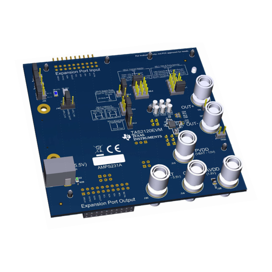
TAS2120 Evaluation Module
Description
The TAS2120EVM has been designed to demonstrate
the performance of TAS2120 in a mono configuration.
The EVM utilizes the AC-MB to provide a USB to
Audio interface to the EVM. Up to four devices
can share a common bus through I
2
I
C interfaces. The TAS2120EVM supports a dual-
mono configuration combining two TAS2120EVMs or
TAS2120EVM and TAS2320EVM.
Get Started
1. Order the
TAS2120EVM
download PPC3 from
2. Read the
TAS2120 data
3. Visit
e2e forum
for any questions.
SLAU936 – AUGUST 2024
Submit Document Feedback
2
S/TDM and
and request access to
TAS2120 product
folder.
sheet.
TAS2120 Mono Evaluation Module
Copyright © 2024 Texas Instruments Incorporated
Features
•
Mono speaker evaluation
•
Plug-n-play hardware mode
•
Advanced software mode interface using
PurePath
™
Console 3 Windows
•
EVM interconnection for stereo testing
•
USB input
2
2
•
External I
C and I
S/TDM host controller
connection available
Applications
•
Mobile
phone,
tablets
•
Smart speakers with voice assistance
•
Bluetooth and wireless speakers
Description
®
software
and
wearables
TAS2120 Evaluation Module
1
Advertisement
Table of Contents

Subscribe to Our Youtube Channel
Related Manuals for Texas Instruments TAS2120


Summary of Contents for Texas Instruments TAS2120
- Page 1 Description Features The TAS2120EVM has been designed to demonstrate • Mono speaker evaluation the performance of TAS2120 in a mono configuration. • Plug-n-play hardware mode The EVM utilizes the AC-MB to provide a USB to • Advanced software mode interface using Audio interface to the EVM.
-
Page 2: Kit Contents
4V to 5.5V. 1.3 Specification The TAS2120 is a digital input Class-D audio amplifier optimized for delivering best battery life for music playback and voice calls. The integrated boost operation is flexible so that TAS2120 can be implemented in 1S and 2S battery applications. - Page 3 SEL5_CLASSH OUT_P SEL4_ADDR OUT_N SEL3_SDA SEL2_SCL Optional Components if EMI SEL1 filtering is required PGND BGND Figure 1-3. Application Diagram for 3S Battery System SLAU936 – AUGUST 2024 TAS2120 Evaluation Module Submit Document Feedback Copyright © 2024 Texas Instruments Incorporated...
-
Page 4: Device Information
1.4 Device Information TAS2120 is a mono, digital-input, Class-D audio amplifier optimized for efficiently driving high peak power into small loudspeaker applications. The Class-D amplifier is capable of delivering 6W of max average power into 8Ω load at a battery voltage of 4.2V. Up to four devices can share a common bus via I S/TDM and I C interfaces. - Page 5 At this moment, the device is powered up and running, ready to play audio. The evaluation kit works as any other sound card, select the EVM as system playback device and use any software like web browser, media player, and so forth. SLAU936 – AUGUST 2024 TAS2120 Evaluation Module Submit Document Feedback Copyright © 2024 Texas Instruments Incorporated...
- Page 6 The AC-MB is detected by the OS as an audio device with the name TI USB Audio UAC2.0. The AC-MB audio setting for the USB mode of operation is shown in Figure 3-2. Figure 3-2. AC-MB USB Audio Setting TAS2120 Evaluation Module SLAU936 – AUGUST 2024 Submit Document Feedback Copyright © 2024 Texas Instruments Incorporated...
- Page 7 How to connect the external audio interface with the bottom row for the ground and the top row for signals is shown in Figure 3-4. Figure 3-4. AC-MB Connection with External Audio Serial Interface SLAU936 – AUGUST 2024 TAS2120 Evaluation Module Submit Document Feedback Copyright © 2024 Texas Instruments Incorporated...
- Page 8 • Place back jumper J3 - IOVDD_MB on AC-MB to the desired selection (1.8V or 3.3V) Figure 3-5. Power -Supply Distribution of the AC-MB TAS2120 Evaluation Module SLAU936 – AUGUST 2024 Submit Document Feedback Copyright © 2024 Texas Instruments Incorporated...
- Page 9 Open Additional SDA pull-up. Open Additional SCL pull-up. VBAT (U1) (J5) VIN (J21) VBAT pin on TAS2120 powered from J21, refer to Section 3.7. VBAT_SNS (J4) VBAT_SNS pin connected to GND. IOVDD powered from IOVDD_MB when shorted, refer to Section Short 3.5.
- Page 10 J3 on the bottom side of the EVM can be used to open this power supply connection for current measurement purposes. If J3 is open, then an external IOVDD must be connected to the IOVDD test point close to TAS2120 - 3.6 AVDD Power Supply Options...
-
Page 11: Speaker Outputs
If using Hardware mode for 2-Channel configuration, then R19 located in the center of the bottom side of the PCB must be removed from the EVM to isolate SEL2 for each EVM. SLAU936 – AUGUST 2024 TAS2120 Evaluation Module Submit Document Feedback Copyright © 2024 Texas Instruments Incorporated... - Page 12 Connect LO of DMM to pin-2 and LO_SNS of DMM to pin-1 of TP20 test point. Figure 3-9. Load DC Resistance Measurement in 4-Wire Mode using Digital Multimeter TAS2120 Evaluation Module SLAU936 – AUGUST 2024 Submit Document Feedback Copyright © 2024 Texas Instruments Incorporated...
- Page 13 OUTPUT OUTPUT HCTRL1 (EXT) I2C_SCL I2C_SCL 33.0 SEL2_SCL1 I2C_SDA I2C_SDA I2C_SDA I2C_SDA I2C_SCL 33.0 I2C_SCL SEL3_SDA1 Figure 4-2. TAS2120EVM Schematic (Sheet 2 of 4) SLAU936 – AUGUST 2024 TAS2120 Evaluation Module Submit Document Feedback Copyright © 2024 Texas Instruments Incorporated...
- Page 14 +1.8V_LDO 1.50k 1.50k VCCA VCCB SCL_+1.8V I2C_SCL SCL_A SCL_B SDA_+1.8V I2C_SDA SDA_A SDA_B 24FC512-I/ST IOVDD_BUFF TCA9416DDF Figure 4-3. TAS2120EVM Schematic (Sheet 3 of 4) TAS2120 Evaluation Module SLAU936 – AUGUST 2024 Submit Document Feedback Copyright © 2024 Texas Instruments Incorporated...
-
Page 15: Pcb Layouts
SPC02SYAN INPUT = 3V-5.5V PWMCL OUTPUT = 14V@2A Figure 4-4. TAS2120EVM Schematic (Sheet 4 of 4) 4.2 PCB Layouts Figure 4-5. TAS2120EVM Top Overlay SLAU936 – AUGUST 2024 TAS2120 Evaluation Module Submit Document Feedback Copyright © 2024 Texas Instruments Incorporated... - Page 16 Hardware Design Files www.ti.com Figure 4-6. TAS2120EVM Top Solder Mask Figure 4-7. TAS2120EVM Top Layer TAS2120 Evaluation Module SLAU936 – AUGUST 2024 Submit Document Feedback Copyright © 2024 Texas Instruments Incorporated...
- Page 17 Hardware Design Files Figure 4-8. TAS2120EVM Layer 2 Figure 4-9. TAS2120EVM Layer 3 SLAU936 – AUGUST 2024 TAS2120 Evaluation Module Submit Document Feedback Copyright © 2024 Texas Instruments Incorporated...
- Page 18 Hardware Design Files www.ti.com Figure 4-10. TAS2120EVM Layer 4 Figure 4-11. TAS2120EVM Layer 5 TAS2120 Evaluation Module SLAU936 – AUGUST 2024 Submit Document Feedback Copyright © 2024 Texas Instruments Incorporated...
- Page 19 Hardware Design Files Figure 4-12. TAS2120EVM Bottom Layer Figure 4-13. TAS2120EVM Bottom Solder Mask SLAU936 – AUGUST 2024 TAS2120 Evaluation Module Submit Document Feedback Copyright © 2024 Texas Instruments Incorporated...
- Page 20 Hardware Design Files www.ti.com Figure 4-14. TAS2120EVM Bottom Overlay TAS2120 Evaluation Module SLAU936 – AUGUST 2024 Submit Document Feedback Copyright © 2024 Texas Instruments Incorporated...
- Page 21 GRM155R61E104KA87D MuRata X5R, 0402 Blue LED, Blue, SMD LED_0805 LTST-C170TBKT Lite-On Green LED, Green, SMD LED_0603 LTST-C191KGKT Lite-On H1, H7 HNSS440 B&F Fastener Supply SLAU936 – AUGUST 2024 TAS2120 Evaluation Module Submit Document Feedback Copyright © 2024 Texas Instruments Incorporated...
- Page 22 0.650" W x 0.200" H - 10,000 per roll 0.200 inch R1, R18, R19, RES, 0, 5%, 0.05 W, 0201 0201 CRCW02010000Z0ED Vishay-Dale R77, R78, R99 TAS2120 Evaluation Module SLAU936 – AUGUST 2024 Submit Document Feedback Copyright © 2024 Texas Instruments Incorporated...
- Page 23 SH-J9, SH-J10, SH-J21, SH- Closed Top 100mil Sullins Connector J28, SH-J29, Shunt, 100mil, Flash Gold, Black SPC02SYAN Shunt Solutions SH-J32, SH- J33, SH-J48, SH-J49, SH- SLAU936 – AUGUST 2024 TAS2120 Evaluation Module Submit Document Feedback Copyright © 2024 Texas Instruments Incorporated...
- Page 24 CAP, CERM, 1000pF, 25V, +/- 10%, C10, C24, C30 1000pF 0201 C0603X5R1E102K030BA X5R, 0201 CAP, CERM, 10uF, 10V, +/- 10%, 10uF 0805 C0805C106K8PACTU Kemet X5R, 0805 TAS2120 Evaluation Module SLAU936 – AUGUST 2024 Submit Document Feedback Copyright © 2024 Texas Instruments Incorporated...
- Page 25 Ferrite Bead, 300 ohm at 100MHz, 300 ohm 0806 NFZ2MSM301SN10L MuRata 3.1A, 0806 RES, 240 k, 1%, 0.063 W, AEC- 240k 0402 CRCW0402240KFKED Vishay-Dale Q200 Grade 0, 0402 SLAU936 – AUGUST 2024 TAS2120 Evaluation Module Submit Document Feedback Copyright © 2024 Texas Instruments Incorporated...
- Page 26 Closed Top 100mil Sullins Connector SH-J6, SH-J8, Shunt, 100mil, Flash Gold, Black SPC02SYAN Shunt Solutions SH-J11 Fully Integrated Synchronous Boost VQFN-HR11 TPS61288RQQR Texas Instruments Converter TAS2120 Evaluation Module SLAU936 – AUGUST 2024 Submit Document Feedback Copyright © 2024 Texas Instruments Incorporated...
-
Page 27: Additional Information
Additional Information 5 Additional Information 5.1 Trademarks PurePath ™ is a trademark of Texas Instruments. Windows ® is a registered trademark of Microsoft Corporation. All trademarks are the property of their respective owners. SLAU936 – AUGUST 2024 TAS2120 Evaluation Module Submit Document Feedback Copyright ©... - Page 28 STANDARD TERMS FOR EVALUATION MODULES Delivery: TI delivers TI evaluation boards, kits, or modules, including any accompanying demonstration software, components, and/or documentation which may be provided together or separately (collectively, an “EVM” or “EVMs”) to the User (“User”) in accordance with the terms set forth herein.
- Page 29 www.ti.com Regulatory Notices: 3.1 United States 3.1.1 Notice applicable to EVMs not FCC-Approved: FCC NOTICE: This kit is designed to allow product developers to evaluate electronic components, circuitry, or software associated with the kit to determine whether to incorporate such items in a finished product and software developers to write software applications for use with the end product.
- Page 30 www.ti.com Concernant les EVMs avec antennes détachables Conformément à la réglementation d'Industrie Canada, le présent émetteur radio peut fonctionner avec une antenne d'un type et d'un gain maximal (ou inférieur) approuvé pour l'émetteur par Industrie Canada. Dans le but de réduire les risques de brouillage radioélectrique à...
- Page 31 www.ti.com EVM Use Restrictions and Warnings: 4.1 EVMS ARE NOT FOR USE IN FUNCTIONAL SAFETY AND/OR SAFETY CRITICAL EVALUATIONS, INCLUDING BUT NOT LIMITED TO EVALUATIONS OF LIFE SUPPORT APPLICATIONS. 4.2 User must read and apply the user guide and other available documentation provided by TI regarding the EVM prior to handling or using the EVM, including without limitation any warning or restriction notices.
- Page 32 Notwithstanding the foregoing, any judgment may be enforced in any United States or foreign court, and TI may seek injunctive relief in any United States or foreign court. Mailing Address: Texas Instruments, Post Office Box 655303, Dallas, Texas 75265 Copyright © 2023, Texas Instruments Incorporated...
- Page 33 TI products. TI’s provision of these resources does not expand or otherwise alter TI’s applicable warranties or warranty disclaimers for TI products. TI objects to and rejects any additional or different terms you may have proposed. IMPORTANT NOTICE Mailing Address: Texas Instruments, Post Office Box 655303, Dallas, Texas 75265 Copyright © 2024, Texas Instruments Incorporated...
Need help?
Do you have a question about the TAS2120 and is the answer not in the manual?
Questions and answers