Subscribe to Our Youtube Channel
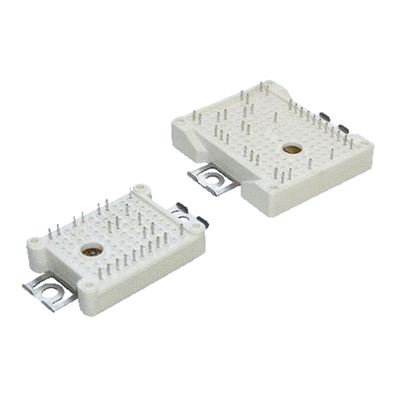
Summary of Contents for Infineon Easy B Series
- Page 1 Application Note AN 2006-08 V2.1 April 2013 E a s y B - S e r i e s M o d u l e s M o u n t i n g I n s t r u c t i o n s f o r E a s y P I M ™ a n d E a s y P A C K M o d u l e s IFAG IPC...
- Page 2 Components may only be used in life-support devices or systems with the express written approval of Infineon Technologies, if a failure of such components can reasonably be expected to cause the failure of that life-support device or system, or to affect the safety or effectiveness of that device or system. Life support devices or systems are intended to be implanted in the human body, or to support and/or maintain and sustain and/or protect human life.
-
Page 3: Table Of Contents
Application Note AN 2006-08 V2.1 April 2013 M o u n t i n g i n s t r u c t i o n s E a s y B - S e r i e s Table of contents 1 General information ............................ -
Page 4: General Information
Application Note AN 2006-08 V2.1 April 2013 M o u n t i n g i n s t r u c t i o n s E a s y B - S e r i e s General information The mounting instructions outlined below are recommended for the safe and reliable operation of the above mentioned modules in typical applications. -
Page 5: Soldering The Module To A Printed Circuit Board (Pcb)
The through holes in the PCB are not required if the soldering is done after mounting to the heat sink (Picture 3). In this case the heat sink’s mass has to be considered during the soldering process. Infineon Holes screwing... -
Page 6: Mounting A Pcb To The Module
An electronically controlled or at least slowly turning electric screwdriver n ≤ 300 rpm is the preferred mounting tool. Due to the lack of accuracy we do not recommend the use of pneumatic screwdrivers or manual screwdrivers. Infineon Figure 4 Cross-sectional view of the mounting stand offs The effective length of the thread in the stand-off should have a minimum of 4mm and a maximum length of 8 The initial 1.5 mm of the mounting stand-off serves as guidance only and cannot take any force. -
Page 7: Condition Of The Heat Sink For Module Assembly
Application Note AN 2006-08 V2.1 April 2013 M o u n t i n g i n s t r u c t i o n s E a s y B - S e r i e s Condition of the heat sink for module assembly The power loss occurring in the module has to be dissipated via heatsink in order not to exceed the maximum permissible temperature T specified in the datasheets during operation. -
Page 8: Assembling The Module On The Heat Sink
Application Note AN 2006-08 V2.1 April 2013 M o u n t i n g i n s t r u c t i o n s E a s y B - S e r i e s Before the module is mounted onto the heat sink an even layer of thermal paste, 80 µm thick, should be applied to the module base or to the heat sink according to the module size and used thermal paste. - Page 9 After positioning of the module it can be fixed by screwing both screws simultaneously (Pic.6a) or the module can be held in place with a force of approximately 10 N during the mounting process (Pic. 6b). This 10 N force it used to prevent cantilevering of the module when the first screw is torqued. Infineon Infineon Infineon...
-
Page 10: System Consideration
A low compressive load to the module is preferred. Therefore, the circuit board should additionally be fixed to the heat sink at a position close to the module. Two options are possible: Infineon Distance keeper h = 12 ± 0.3 mm... -
Page 11: The Module Will Be Soldered To The Pcb Before Mounting It Onto The Heat Sink
Application Note AN 2006-08 V2.1 April 2013 M o u n t i n g i n s t r u c t i o n s E a s y B - S e r i e s Figure 8 Fixing of the PCB. -
Page 12: Storage And Transport
Storage of the modules at the limits of the temperature specified in the datasheet is possible, however, not recommended. The recommended storage conditions according to Infineon TR14 (Application Note “Storage of Products Supplied by Infineon Technologies) and IEC60721-3-1, class 1K2 should be assured for the recommended storage time of max. 2 years. Max. air temperature: T =+40°C... - Page 13 Application Note AN 2006-08 V2.1 April 2013 M o u n t i n g i n s t r u c t i o n s E a s y B - S e r i e s...


Need help?
Do you have a question about the Easy B Series and is the answer not in the manual?
Questions and answers