Table of Contents
Advertisement
Quick Links
Advertisement
Table of Contents

Related Manuals for Premio BCO-1000-ADLN


Summary of Contents for Premio BCO-1000-ADLN
- Page 1 USER’S MANUAL BCO-1000-ADLN Basic Fanless Embedded Computer...
-
Page 2: Table Of Contents
BCO-1000-ADLN l User’s Manual Table of Contents Prefaces …………………………………………………….……………………………………………. 04 Revision …………………………………………………………………………………………..……………….……….. 04 Disclaimer ………………………………………………………..…….…….………………………….……………….. 04 Copyright Notice …………………………………….…………………….…………………………………………… 04 Trademarks Acknowledgment …………..………………………………………………………....04 Environmental Protection Announcement …………………………….………………….……………….. 04 Safety Precautions ………………………………………….……………………………….…………….………….. 05 Technical Support and Assistance …………………………………….…………….…………….…………….06 Conventions Used in this Manual ………………………………………………………………….….………..06 Package Contents …………………………………………………………………………………………….…………... - Page 3 BCO-1000-ADLN l User’s Manual Install M.2 ……………………..………………….………………………………......41 Install 2.5-inch hard drive ..………………………..…….……..……………………..……..43 Installing wall mount kit ……………………………………………………………....46 Installing DIN rail holder .…..….……………………………………......48 Chapter 4 BIOS Setup ……………..…………………………………………………..……… 49 BIOS Setup .…………………………………………………………………………………..…..…... 50 The Menu Bar …………………………….……………………………………..………………..52 4.2.1 Menu ………………………………………………………………………..…………...………...
-
Page 4: Prefaces
2024/04/18 Disclaimer All specifications and information in this User’s Manual are believed to be accurate and up to date. Premio Solution Inc. does not guarantee that the contents herein are complete, true, accurate or non-misleading. The information in this document is subject to change without notice and does not represent a commitment on the part of Premio Inc. -
Page 5: Safety Precautions
Preface BCO-1000-ADLN l User’s Manual Safety Precautions Before installing and using the equipment, please read the following precautions: ⚫ Put this equipment on a reliable surface during installation. Dropping it or letting it fall could cause damage. ⚫ The power outlet shall be installed near the equipment and shall be easily accessible. -
Page 6: Technical Support And Assistance
Preface BCO-1000-ADLN l User’s Manual Technical Support and Assistance 1. Visit the Premio Inc website at www.premioinc.com where you can find the latest information about the product. 2. Contact your distributor, our technical support team or sales representative for technical support if you need additional assistance. -
Page 7: Package Contents
Before installation, please ensure all the items listed in the following table are included in the package. Item Description Q’ty BCO-1000-ADLN Basic Fanless Embedded Computer Wall Mount Kit Accessory Kit Adapter AC/DC 12V 5A 60W with 3pin Terminal Block Plug 5.0mm Pitch... -
Page 8: Chapter 1 Product Introductions
Chapter 1 Product Introductions... -
Page 9: Overview
Chapter 1: Product Introductions 1.1 Overview Premio Basic Fanless Embedded Systems are designed for entry-level applications and basic needs. The BCO series can oversee connected devices and manage the collection, storage, and transmission of sensor data, and is capable of distilling unexplored value in data. It is not only robust and can withstand dust, shock, and vibration, but also can suitable for industrial automation, industrial control, kiosk &... -
Page 10: Hardware Specification
BCO-1000-ADLN l User’s Manual Chapter 1: Product Introductions 1.2 Hardware Specification System Processor Support 12th Gen Intel® IoTG Alder Lake-N Processor N97, QC, 12W System Chipset SoC integrated LAN Chipset 2x Intel® I225-V 2.5GbE LAN Audio Codec Realtek ALC897 System Memory DDR5 4800MT/s SODIMM. - Page 11 BCO-1000-ADLN l User’s Manual Chapter 1: Product Introductions Environment 0 ° C to 50 ° C (12W CPU) Operating Temp. Tested according to: IEC60068-2-1:2007 (Cold test procedure) IEC60068-2-2:2007 (Dry heat test procedure) IEC60068-2-3:2007 (Damp heat, steady state, test procedure) IEC60068-2-14:2009 (Wide temperature range thermal shock) -30 °...
-
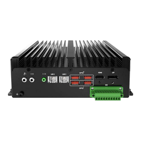
Page 12: System I/O
BCO-1000-ADLN l User’s Manual Chapter 1: Product Introductions 1.3 System I/O BCO-1000-ADLN Front Panel USB 3.2 Gen 2 port (10 Gbps) Line-in / Line-out Used to connect USB 3.2 device Used to connect a speaker USB 3.2 Gen 1 port (5 Gbps) Mic-in Used to connect USB 3.2 device... - Page 13 BCO-1000-ADLN l User’s Manual Chapter 1: Product Introductions BCO-1000-ADLN Rear Panel USB 2.0 port DC IN Used to connect USB 2.0 device Used to plug a DC power input with terminal block COM port COM1 ~ COM2 support RS232/422/485 serial...
-
Page 14: Mechanical Dimension
BCO-1000-ADLN l User’s Manual Chapter 1: Product Introductions 1.4 Mechanical Dimensions BCO-1000-ADLN Unit: mm... -
Page 15: Chapter 2 Mechanical Specifications
Chapter 2 Mechanical Specifications... -
Page 16: Switch And Connector Locations
BCO-1000-ADLN l User’s Manual Chapter 2: Mechanical Specifications 2.1 Switch and Connector Locations 2.1.1 TopView Rear I/OPanel SYSFAN1 JAUD1 JLVDS1 JAMP1 JRTC1 JSMB1 JCOM2 JVDD1 JINV1 JCOM1 JINVDD1 JCOMP1 JEDP_VDD1 JGPIO1 JEDP1 JPWR1 JFP1 JUSB2 JUSB1 SATA1 M2_B1 JATX1 M2_E1... -
Page 17: Rear I/O Panel
BCO-1000-ADLN l User’s Manual Chapter 2: Mechanical Specifications 2.1.2 Rear I/O Panel 2.5GbE Line-Out USB 3.2Gen 1Ports DisplayPort RJ-45 LAN Jacks Jack USB 3.2Gen 2Ports DisplayPort DisplayPortisa digitaldisplay interfacestandard. Thisconnector isused toconnect a monitor withDisplayPortinputs. Connector The High-DefinitionMultimedia Interface (HDMI ) is an all-digitalaudio/ video interface capable oftransmitting uncompressed streams. -
Page 18: Gbe Rj-45 Lan Jack
BCO-1000-ADLN l User’s Manual Chapter 2: Mechanical Specifications 2.1.3 2.5 GbE RJ-45 LAN Jack 2.5 GbE RJ-45 LAN Jack The standard singleRJ45 LAN jackisprovided forconnectiontothe LocalArea Network (LAN).You can connect a network cable toit. Link/ Activity LED Speed LED Status... -
Page 19: Board Dimension
BCO-1000-ADLN l User’s Manual Chapter 2: Mechanical Specifications 2.1.4 Board Dimension Unit: mm... -
Page 20: Component Contents
BCO-1000-ADLN l User’s Manual Chapter 2: Mechanical Specifications 2.2 Component Contents Component Component Memory JLVDS1: LVDS Wafer Connector DIMM1: DDR5 SO DIMM Slot JINVDD1: LVDS Inverter Box Header Storage JEDP1: eDP Connector SATA1: SATA 3.06Gb/s Port M2_B1: M.2 Slot(B Key, 2242,3042, 2280) - Page 21 BCO-1000-ADLN l User’s Manual Chapter 2: Mechanical Specifications Memory DIMM1 : DDR5 SO DIMM Slot The SO-DIMM slotsisintendedformemory modules. DIMM1 Installing DDR5 Memory 1.LocatetheSO-DIMM slot.AlignthenotchontheDIMM withthekey ontheslot and inserttheDIMM intotheslot. 2.Push the DIMM gentlydownwards untilthe slotleversclickand lockthe DIMM inplace. 3.TouninstalltheDIMM, fliptheslotleversoutwards and theDIMM willbe released instantly.
- Page 22 BCO-1000-ADLN l User’s Manual Chapter 2: Mechanical Specifications Storage SATA1 : SATA 3.0 6Gb/s Port This connector is SATA 6Gb/s interface port, it can connect to one SATA device. SATA1 Important • This SATA port supports hot plug. • Please do not fold the SATA cable at a 90-degree angle. Data loss may result during transmission otherwise.
- Page 23 BCO-1000-ADLN l User’s Manual Chapter 2: Mechanical Specifications M2_B1 : M.2 Slot (B Key, 2242, 3042, 2280) Please install the solid-state drive (SSD) into the M.2 slot as shown below. Feature ∙ SupportsSATA 3.0signal. ∙ SupportsB+M KeySATA 3.0SSD. Installing M.2 SSD 1.Loosen the M.2 riser...
-
Page 24: Expansion Slots
BCO-1000-ADLN l User’s Manual Chapter 2: Mechanical Specifications Expansion Slots Expansion Slots M2_B1: M.2 Slot (B Key, 2242, 3042, 2280) Please install the module card into the M.2 slot as shown below. M2_B1 M2_E1 Feature • SupportsPCIex1signal. • SupportsB+M keyPCIex1module. - Page 25 BCO-1000-ADLN l User’s Manual Chapter 2: Mechanical Specifications M2_E1: M.2 Slot (E Key, 2230) Please install the Wi-Fi/ Bluetooch card into the M.2 slot as shown below. Feature • Supports PCIe x1 & USB 2.0 signal. • Supports Intel® Wi-Fi 6E AX210 + BT 5.2 wireless card.
- Page 26 BCO-1000-ADLN l User’s Manual Chapter 2: Mechanical Specifications Connectors Power Connectors JPWR1 JPW1 JPWR1: 4-Pin DC-In Main Power Connector This connector allows you to connect an power supply. DC-IN DC-IN JPWR1 JPW1: 4-Pin SATA Power Connector This connector is used to provide power to SATA devices.
-
Page 27: Audio Connectors
BCO-1000-ADLN l User’s Manual Chapter 2: Mechanical Specifications Audio Connectors JAUD1 JAMP1 JAUD1: Front Audio Header This connector allows you to connect front panel audio. LINE_IN_RA MIC1_RA LINE_IN_LA MIC1_LA LOUT_RA MIC1_JD JAUD1 LOUT_LA LINE_IN_JD FRONT_JD JAMP1: Audio Amplifier Header The connector is used to connect audio amplifiers to enhance audio performance.. - Page 28 BCO-1000-ADLN l User’s Manual Chapter 2: Mechanical Specifications Graphics Connectors JLVDS1: LVDS Wafer Connector This connector is designed for use JLVDS1 with LVDS interface flat panels. When connecting your flat panel JINVDD1 to this connector, be sure to check the panel datasheet to ensure that...
- Page 29 BCO-1000-ADLN l User’s Manual Chapter 2: Mechanical Specifications JINVDD1: LVDS Inverter Box Header The connector is provided for LCD backlight options, be sure to check the panel datasheet to ensure that you set the LVDS Inverter Power Select Jumper (JINV1) to the appropriate power voltage (5V/12V).
-
Page 30: Other Connectors
BCO-1000-ADLN l User’s Manual Chapter 2: Mechanical Specifications Other Connectors SYSFAN1: PWM System Fan Box Header The fan power connector supports system cooling fans with +12V. When connecting the wire to the connectors, always note that the red wire is the positive and should be connected to the +12V;... - Page 31 BCO-1000-ADLN l User’s Manual Chapter 2: Mechanical Specifications JCOM1, JCOM2: COM Port Box Headers This connector is a 16550A high speed communications port that sends/ receives 16 bytes FIFOs. You can attach a serial device to it. DCD# SOUT DSR#...
- Page 32 BCO-1000-ADLN l User’s Manual Chapter 2: Mechanical Specifications JGPIO1: GPIO (DIO) Box Header This connector is provided for the General-Purpose Input/Output (GPIO) peripheral module. VCC5 GPO0 GPI0 JGPIO1 GPO1 GPI1 GPO2 GPI2 GPO3 GPI3 JUSB1~3: USB 2.0 Box Headers These connectors are ideal for connecting USB devices such as keyboard, mouse, or other USB-compatible devices.
- Page 33 BCO-1000-ADLN l User’s Manual Chapter 2: Mechanical Specifications JRTC1: CMOS Battery Header If the CMOS battery is out of charge, the time in the BIOS will be reset and the data of system configuration will be lost. In this case, you need to replace the CMOS battery.
- Page 34 BCO-1000-ADLN l User’s Manual Chapter 2: Mechanical Specifications Jumpers Important Avoid adjusting jumpers when the system is on; it will damage the motherboard. JVDD1 JINV1 JEDP_VDD1 JCOMP1 JCMOS1 JCSE_DIS1 JATX1 Jumper Name Default Setting Description COM Power Select Jumper JCOMP1...
- Page 35 BCO-1000-ADLN l User’s Manual Chapter 2: Mechanical Specifications Jumper Name Default Setting Description LVDS Inverter Power Select Jumper JINV1 1-2: 5V (Default) 2-3: 12V eDP Power Select Jumper JEDP_VDD1 1-2: 5V 2-3: 3V (Default)
-
Page 36: Chapter 3 System Setup
Chapter 3 System Setup... -
Page 37: Set Torque Force To 3.5 Kgf-Cm To Screw Or Unscrew System Parts
BCO-1000-ADLN l User’s Manual Chapter 3: System Setup 3.1 Set torque force to 3.5 kgf-cm to screw or unscrew system parts. 3.2 Before installing the system, separate the top and the bottom covers To ensure safety and prevent system damage, before disassembly, please switch off the system and disconnect the unit from its power source. - Page 38 BCO-1000-ADLN l User’s Manual Chapter 3: System Setup 2. Remove the 2 screws on the left and right side of the system as highlighted in the pictures below...
- Page 39 BCO-1000-ADLN l User’s Manual Chapter 3: System Setup 3. After opening the bottom cover, remove the top and bottom cable covers to facilitate the installation of hard drives and memory.
-
Page 40: Install Ram
BCO-1000-ADLN l User’s Manual Chapter 3: System Setup 3.3 Install RAM 1. Insert at 45 degree angle 2. Press down lightly... -
Page 41: Install M.2
BCO-1000-ADLN l User’s Manual Chapter 3: System Setup 3.4 Install M.2 1. Loosen the screw 2. Insert M.2 at 45 degree angle... - Page 42 BCO-1000-ADLN l User’s Manual Chapter 3: System Setup 3. After pressing M.2, lock the screw...
-
Page 43: Install 2.5-Inch Hard Drive
BCO-1000-ADLN l User’s Manual Chapter 3: System Setup 3.5 Install 2.5-inch hard drive 1. Remove the screws 2. Open the lid... - Page 44 BCO-1000-ADLN l User’s Manual Chapter 3: System Setup 3. Install the 2.5-inch hard drive...
- Page 45 BCO-1000-ADLN l User’s Manual Chapter 3: System Setup 4. Lock the screws...
-
Page 46: Installing Wall Mount Kit
Chapter 3: System Setup 3.6 Installing wall mount kit 1. Wall mount kit is available for BCO-1000-ADLN included in the standard package. 2. Place the system upside down so you can see the bottom cover. The highlighted screw holes below will be used. - Page 47 BCO-1000-ADLN l User’s Manual Chapter 3: System Setup 3. Lock the wall mount kit with eight screws (M3x5L, Nylok).
-
Page 48: Installing Din Rail Holder
Chapter 3: System Setup 3.7 Installing DIN rail holder 1. Din rail holder is available for BCO-1000-ADLN series as optional accessories. 2. Place the system upside down so you can see the bottom cover. The highlighted screw holes below will be used. -
Page 49: Chapter 4 Bios Setup
Chapter 4 BIOS Setup... -
Page 50: Bios Setup
BCO-1000-ADLN l User’s Manual Chapter 4: BIOS Setup 4.1 BIOS Setup Thischapter provides information on the BIOS Setup program and allows users to configurethe system foroptimal use. Users may need to run the Setup program when: • An errormessage appears on thescreen atsystemstartupand requests users to run SETUP. -
Page 51: Bios Introduction
BCO-1000-ADLN l User’s Manual Chapter 4: BIOS Setup BIOS Introduction Control Keys SelectScreen ↑ ↓ SelectItem Enter Select Change Value Exit GeneralHelp Previous Values Optimized Defaults Save& Reset* Screenshotcapture Scrollhelpareaupwards <K> <M> Scrollhelparea downwards *When you press <F10>,a confirmation window appears and i t provides the modificationinformation.Selectbetween Yes orNo toconfirm yourchoice. -
Page 52: The Menu Bar
BCO-1000-ADLN l User’s Manual Chapter 4: BIOS Setup 4.2 The Menu Bar Main Use thismenu forbasicsystem configurations, such as time,date,etc. Advanced Use thismenu tosetup theitems ofspecialenhanced features. Boot Use thismenu tospecifythepriorityofbootdevices. Security Use thismenu tosetsupervisor and userpasswords. Chipset Thismenu controlstheadvanced featuresofthe on-board chipsets. -
Page 53: Menu
BCO-1000-ADLN l User’s Manual Chapter 4: BIOS Setup 4.2.1 Menu HDD Information • RAID (VMD) Disabled: Display HDD information as plugging in status. • RAID (VMD) Enabled: Display "Empty" only. *SATA_2 is for M.2 B key (SATA signal) System Date This setting allows you to set the system date. -
Page 54: Advanced
BCO-1000-ADLN l User’s Manual Chapter 4: BIOS Setup 4.2.2 Advanced Full Screen Logo Display This BIOS feature determines if the BIOS should hide the normal POST messages with the motherboard or system manufacturer’s full-screen logo. BIOS will display the full-screen logo during the boot-up sequence, hiding [Enabled] normal POST messages. -
Page 55: Cpu Configuration
BCO-1000-ADLN l User’s Manual Chapter 4: BIOS Setup CPU Configuration Intel Virtualization Technology Enables ordisablesIntelVirtualizationtechnology. Enables IntelVirtualizationtechnologyand allowsa platformto run [Enabled] multipleoperating systems inindependent partitions. The system can functionas multiplesystems virtually. Disables thisfunction. [Disabled] Active Efficient-cores Selectthenumber ofactiveEfficient-cores(E-cores). Intel(R) SpeedStep(TM) Enhanced IntelSpeedStep®... - Page 56 BCO-1000-ADLN l User’s Manual Chapter 4: BIOS Setup Intel(R) Speed Shift Technology Intel® Speed ShiftTechnology isan energy-efficient method that allows frequency control by hardware ratherthan theOS. [Enabled] When enabled, Intel®Speed ShiftTechnology isactivated. The technologyenables the management ofprocessor power consumption via hardware performance state (P-State) transitions.
-
Page 57: Super Io Configuration
BCO-1000-ADLN l User’s Manual Chapter 4: BIOS Setup Super IO Configuration Serial Port 1/ 2 Thissettingenables ordisablesthe specifiedserialport. » Change Settings This setting isused tochange the address & IRQ settings ofthe specified serial port. » Mode Select Select an operationmode forSerialPort1/2. - Page 58 BCO-1000-ADLN l User’s Manual Chapter 4: BIOS Setup H/W Monitor (PC Health Status) These items display the current status of all monitored hardware devices/ components such as voltages, temperatures and all fans’ speeds. Thermal Shutdown Thissettingdetermines thebehavior ofthesystemwhen theCPU temperature reachesapredefined threshold.
- Page 59 BCO-1000-ADLN l User’s Manual Chapter 4: BIOS Setup PCI/PCIE Device Configuration Audio Controller Thissettingenables ordisablesthe detection oftheonboard audiocontroller. Network Stack Configuration Thismenu provides NetworkStack settings forusers toenable network boot (PXE) from BIOS. Network Stack Thismenu provides NetworkStack settings forusers toenable network boot (PXE)fromBIOS.The followingitems willdisplaywhen Network Stak isenabled.
- Page 60 BCO-1000-ADLN l User’s Manual Chapter 4: BIOS Setup GPIO Group Configuration GPO0 ~ GPO3 These settings controlthe operationmode ofthe specifiedGPIO. PCIE ASPM settings Thismenu providesettings forPCIe ASPM (ActiveStatePower Management) level fordifferentinstalleddevices. M2_B1/ M2_E1 Sets PCI Express ASPM (Active StatePower Management) state forpower saving.
-
Page 61: Boot
BCO-1000-ADLN l User’s Manual Chapter 4: BIOS Setup 4.3 Boot Boot Option #1-2 Thissettingallows users tosetthe sequence ofboot devices where BIOS attempts toloadthediskoperating system. -
Page 62: Security
BCO-1000-ADLN l User’s Manual Chapter 4: BIOS Setup 4.4 Security Administrator Password Administrator Password controls access tothe BIOS Setup utility. User Password User Password controls access tothe system atboot and tothe BIOS Setup utility. - Page 63 BCO-1000-ADLN l User’s Manual Chapter 4: BIOS Setup PCH-FW Configuration Thismenu allowsyoutoconfiguresettingsrelatedtothePCH firmware. Firmware Information These settingsshow the M E Firmware Version M E System IntegrityValue firmwareinformationof the Firmware Mode M E M E Firmware Status 1-2 IntelM E (Management Engine).
- Page 64 BCO-1000-ADLN l User’s Manual Chapter 4: BIOS Setup Firmware Update Configuration Thismenu willdisplaywhen ME State isenabled. » ME FW Image Re-Flash Enables or disables the M E Firmware Image Re-flashing. » Local FW Update Enables ordisables thecapabilitytoperforma firmwareupdate ofthe M E locally.
- Page 65 BCO-1000-ADLN l User’s Manual Chapter 4: BIOS Setup » CPU Replaced Polling Disable Settingthisoptiondisables the CPU replacement pollingloop. » HECI Message Check Disable This setting disables message check forBIOSbootpath when sending messages. » MBP HOB Skip Setting thisoptionwillskipME’sMemory-Based Protection (MBP) H0B region.
- Page 66 BCO-1000-ADLN l User’s Manual Chapter 4: BIOS Setup Trusted Computing Security Device Support Thisitem enables ordisablesBIOSsupport forsecuritydevice.When setto [Disable],the OS willnotshow securitydevice. SHA256/ SHA384 PCR Bank These settings enables ordisablestheSHA256 PCR Bank and SHA384 PCR Bank. Pending Operation When Security Device Support issetto[Enable],Pending Operation willappear. Itis advised thatusers should routinelyback up theirTPM secured data.
- Page 67 BCO-1000-ADLN l User’s Manual Chapter 4: BIOS Setup Serial Port Console Redirection Console Redirection Console Redirectionoperates inhostsystems thatdo not have a monitor and keyboard attached. Thissettingenables ordisablesthe operationofconsole redirection.When setto[Enabled],BIOS redirectsand sends allcontents that should be displayedonthescreen tothe serialCO M portfordisplay onthe terminal screen.
- Page 68 BCO-1000-ADLN l User’s Manual Chapter 4: BIOS Setup Console Redirection Settings (COM1) » Terminal Type To operate the system’sconsole redirection,you need a terminal supporting ANSI terminal protocoland a RS-232 nullmodem cable connected between the host system and terminal(s).You can selectemulation forthe terminal from thissetting.
- Page 69 BCO-1000-ADLN l User’s Manual Chapter 4: BIOS Setup Secure Boot Secure Boot Secure Bootfunctioncan be enabled onlywhen the Platform Key (PK) isenrolled and running accordingly. Secure Boot Mode Selectsthe secure bootmode. Thisitem appears when Secure Boot isenabled. The system willautomaticallyload the secure keys from BIOS.
- Page 70 BCO-1000-ADLN l User’s Manual Chapter 4: BIOS Setup Key Management Press Enter key toenter thesub-menu. Manage the secure bootkeys.Thisitem appears when “Secure Boot Mode” setsto[Custom]. » Platform Key (PK): The Platform Key (PK) can protect the firmware from any un-authenticated changes.
- Page 71 BCO-1000-ADLN l User’s Manual Chapter 4: BIOS Setup » Append Key Loads an additional db from storagedevices toyour system. » Delete Key Deletes the db from your system. » Forbidden Signatures (dbx): Forbidden Signatures(dbx)liststhe forbidden signatures thatare nottrustedand cannot be loaded.
-
Page 72: Chipset
BCO-1000-ADLN l User’s Manual Chapter 4: BIOS Setup 4.5 Chipset DVMT Total Gfx Mem Thissettingspecifiesthe totalgraphics memory sizeforDynamic Video Memory Technology(DVMT). LVDS Panel Type ThissettingspecifiestheLVDS Panel’sresolutionand distributionformats. Backlight Control ThissettingcontrolstheintensityoftheLED’sbacklightoutput.When lighting conditionsare brighter,setithigh fora clearerimage and lowwhen itisdarker. LED’s backlight output... -
Page 73: Power
BCO-1000-ADLN l User’s Manual Chapter 4: BIOS Setup 4.6 Power Restore AC Power Loss Thissettingspecifieswhether your system willreboot aftera power failureor interrupt occurs.Availablesettings are: [Power Off] Leaves the computer inthe power offstate. Leaves the [Power On] computer inthe power on state. -
Page 74: Save & Exit
BCO-1000-ADLN l User’s Manual Chapter 4: BIOS Setup 4.7 Save & Exit Save Changes and Reset Save changes toCMOS and resetthe system. Discard Changes and Exit Abandon allchanges and exit the Setup Utility. Discard Changes Abandon all changes. Load Optimized Defaults Use thismenu toload thedefaultvalues setby themotherboard manufacturer specificallyfor optimal performance ofthe motherboard. -
Page 75: Appendix Gpio Wdt Bkl Smbusaccess Programming
Appendix GPIO WDT BKL SMBus Access Programming... - Page 76 BCO-1000-ADLN l User’s Manual Appendix – WDT & GPIO GPIO WDT BKL SMBus Access Programming Thischapter provides GPIO (General Purpose Input/Output), W D T (Watch Dog Timer), LVDS Backlight and SMBus Access programming guide. Abstract In this section,code examples based on C programming language provided for customer interest.Inportb, Outportb, Inportl and Outportl are basicfunctions used foraccess IO...
-
Page 77: Generalpurposedio-Gpio/Dio
BCO-1000-ADLN l User’s Manual Appendix – WDT & GPIO 1. General Purposed IO – GPIO/DIO The GPIO port configuration addresses are listed in the following table: Name IO Port IO address Name IO Port IO address N_GPI0 0xA10 Bit 0... -
Page 78: Watchdogtimer-Wdt
BCO-1000-ADLN l User’s Manual Appendix – WDT & GPIO 2. Watchdog Timer – WDT The base address (WDT_BASE) of WDT configuration registers is 0xA10. 2.1 Set WDT Time Unit val = Inportb (WDT_BASE + 0x05); // Read current WDT setting val = val | 0x08;... - Page 79 BCO-1000-ADLN l User’s Manual Appendix – WDT & GPIO 2.5 Check WDT Reset Flag If the system has been reset by WDT function, this flag will set to 1. val = Inportb (WDT_BASE + 0x05); // Read current WDT setting.
-
Page 80: Lvds Backlightcontrol -Bkl
BCO-1000-ADLN l User’s Manual Appendix – WDT & GPIO 3. LVDS Backlight Control – BKL The controller support LVDS backlight level control from 0(0%) to 255(100%), the default backlight level is 100%. It must be controlled by SMBus access. The details of SMBus access (SMBus_ReadByte, SMBus_WriteByte) are provided in this document. -
Page 81: Smbusaccess
BCO-1000-ADLN l User’s Manual Appendix – WDT & GPIO 4. SMBus Access The base address of SMBus must know before access. The relevant bus and device information are as following. #define IO_SC 0xCF8 #define IO_DA 0xCFC #define PCIBASEADDRESS 0x80000000 #define PCI_BUS_NUM... - Page 82 BCO-1000-ADLN l User’s Manual Appendix – WDT & GPIO SMBus_WriteByte (char DEVID, char offset, char DATA) Write DATA to OFFSET on SMBus device DEVID. Outportb (LOWORD (SMBUS_BASE), 0xFE); Outportb (LOWORD (SMBUS_BASE) + 0x04, DEVID); //out Base + 04, (DEVID) Outportb (LOWORD (SMBUS_BASE) + 0x03, OFFSET);...
- Page 83 © Premio Inc. All Rights Reserved www.premioinc.com...
Need help?
Do you have a question about the BCO-1000-ADLN and is the answer not in the manual?
Questions and answers