Table of Contents
Advertisement
Quick Links
Advertisement
Table of Contents

Related Manuals for Premio RCO-6OOO-8L


Summary of Contents for Premio RCO-6OOO-8L
- Page 1 USER’S MANUAL RCO-6000 Series Superior Fanless Embedded System...
-
Page 2: Table Of Contents
RCO-6000 | User’s Manual Table of Contents Prefaces ……………………………………………………………………………………………….. 04 Revision ………………………………………………………..……………………………..……………….……….. 04 Disclaimer ……………………………………………………….…….……………….………………….………….. Copyright Notice …………………………………….…….….………………………………….………………… Trademarks Acknowledgment …………..………….………………………………………....Environmental Protection Announcement ……………………………………..……..……………….. Safety Precautions ……………………………………………………………………………………….….…….. Technical Support and Assistance ………………………………...……………………..…….…….……. Conventions Used in this Manual …………………………………..……………………..….……….. Package Contents ……………………………………………………………………..…..…………………….… Ordering Information …………………………..……………………………………..………..….….…………... - Page 3 RCO-6000 | User’s Manual Chapter 2 Switches and Connectors …………….……………………………………. Switch and connector Locations ………………………………………..…….….……..2.1.1 Top View ………………………………………………………………………..…..……… 2.1.2 Bottom View ……………………………………………………………..……..……….. 48 Connector / Switch Definition ……………………………….……….…….……..... 49 Switch Definitions ………….……………............. 50 Connector Definitions …………………………............. 50 Chapter 3 System Setup …………………………..…………………………….……………...
-
Page 4: Prefaces
RCO-6000 | User’s Manual Prefaces Revision Revision Description Date Manual Released 2016/08/23 Switches and Connectors Revised 2017/09/12 Power Connector Definition Revised 2017/11/02 Upper Cover 2D Drawing Revised 2017/11/29 GPIO Sample Code Revised 2018/02/09 New-added CPU support and OS revision 2018/08/20 WDT &... -
Page 5: Safety Precautions
Preface RCO-6000 | User’s Manual Safety Precautions Before installing and using the equipment, please read the following precautions: Put this equipment on a reliable surface during installation. Dropping it or letting it fall could cause damage. The power outlet shall be installed near the equipment and shall be easily accessible. ... -
Page 6: Technical Support And Assistance
Preface RCO-6000 | User’s Manual Technical Support and Assistance Contact your distributor, our technical support team or sales representative for technical support if you need additional assistance. Please have following information ready before you call: Model name and serial number ... -
Page 7: Package Contents
Preface RCO-6000 | User’s Manual Package Contents Before installation, please ensure all the items listed in the following table are included in the package. Item Description Q’ty RCO-6000 Series Fanless Embedded System Utility DVD Driver Wall Mount Kit Accessory Kit DVI to VGA Adapter Ordering Information Model No. - Page 8 Preface RCO-6000 | User’s Manual Model No. Product Description Superior fanless embedded system with LGA 1151 for Intel® 6 Gen Processor and Q170 PCH, RCO-6011E-4P 2x LAN, 4x PoE, 1x PCIe x16 Expansion Superior fanless embedded system with LGA 1151 for Intel® 6 Gen Processor and Q170 PCH, RCO-6011E-4P-M12 2x LAN, 4x M12 PoE, 1x PCIe x16 Expansion...
-
Page 9: Optional Accessory
Preface RCO-6000 | User’s Manual Model No. Product Description Superior fanless embedded system with LGA 1151 for Intel® 6 Gen Processor and Q170 PCH, RCO-6022PP-8L 10x LAN, 2x PCI Expansion Superior fanless embedded system with LGA 1151 for Intel® 6 Gen Processor and Q170 PCH, RCO-6022PP-8L-M12 2x LAN, 8x M12 LAN, 2x PCI Expansion... -
Page 10: Chapter 1 Product Introductions
Chapter 1 Product Introductions... -
Page 11: Overview
Chapter 1: Product Introductions RCO-6000 | User’s Manual 1.1 Overview Based on 7 Gen. Intel® Core™ i7-7700T (3.8GHz, Quad Core) / i5-7500T (3.3GHz, Quad Core) / i3- 7101TE (3.4GHz, Dual Core) or 6 Gen. Intel® Core™ i7-6700TE (3.4GHz, Quad Core) / i5-6500TE ®... -
Page 12: Hardware Specification
Chapter 1: Product Introductions RCO-6000 | User’s Manual 1.2 Hardware Specification Processor System Storage • Support 6 • 2x Removable 2.5" SATA HDD Bay & 7 Gen Intel® Core™ i7 / i5 / i3 / Pentium® / • 2x Internal 2.5" SATA HDD Bay Celeron®... -
Page 13: System I/O
Chapter 1: Product Introductions RCO-6000 | User’s Manual 1.3 System I/O 1.3.1 RCO-6000 Front Panel Universal I/O Bracket ATX power on/off switch Used to customized I/O output Press to power-on or power-off the system HDD port Reset switch Removable 2.5" SATA HDD Area Press to reset the system Power LED USB 3.0 port... - Page 14 Chapter 1: Product Introductions RCO-6000 | User’s Manual Rear Panel DisplayPort DC IN Used to connect a DisplayPort monitor Used to plug a DC power input with terminal block USB 3.0 port Used to connect USB 3.0/2.0/1.1 device Speaker-out Used to connect a speaker LAN port Used to connect the system to a local area Mic-in...
-
Page 15: Rco-6000-4L(P)
Chapter 1: Product Introductions RCO-6000 | User’s Manual 1.3.2 RCO-6000-4L(P) Front Panel PoE Port Used to connect the system to a local area ATX power on/off switch network with power over Ethernet Press to power-on or power-off the system (RCO-6000-4P Only) Reset switch Universal I/O Bracket Press to reset the system... - Page 16 Chapter 1: Product Introductions RCO-6000 | User’s Manual Rear Panel DisplayPort DC IN Used to connect a DisplayPort monitor Used to plug a DC power input with terminal block USB 3.0 port Used to connect USB 3.0/2.0/1.1 device Speaker-out Used to connect a speaker LAN port Used to connect the system to a local area Mic-in...
-
Page 17: Rco-6000-4L(P)-M12
Chapter 1: Product Introductions RCO-6000 | User’s Manual 1.3.3 RCO-6000-4L(P)-M12 Front Panel M12 PoE Port ATX power on/off switch Used to connect the system to a local area Press to power-on or power-off the system network with power over Ethernet (RCO-6000-4P-M12 Only) Reset switch Press to reset the system... - Page 18 Chapter 1: Product Introductions RCO-6000 | User’s Manual Rear Panel DisplayPort DC IN Used to connect a DisplayPort monitor Used to plug a DC power input with terminal block USB 3.0 port Used to connect USB 3.0/2.0/1.1 device Speaker-out Used to connect a speaker LAN port Used to connect the system to a local area Mic-in...
-
Page 19: Rco-6000-8L(P)
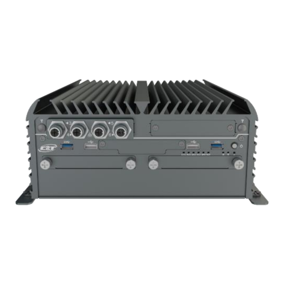
Chapter 1: Product Introductions RCO-6000 | User’s Manual 1.3.4 RCO-6000-8L(P) Front Panel PoE Port ATX power on/off switch Used to connect the system to a local area Press to power-on or power-off the system network with power over Ethernet (RCO-6000-8P Only) Reset switch Press to reset the system HDD port... - Page 20 Chapter 1: Product Introductions RCO-6000 | User’s Manual Rear Panel DisplayPort DC IN Used to connect a DisplayPort monitor Used to plug a DC power input with terminal block USB 3.0 port Used to connect USB 3.0/2.0/1.1 device Speaker-out Used to connect a speaker LAN port Used to connect the system to a local area Mic-in...
-
Page 21: Rco-6000-8L(P)-M12
Chapter 1: Product Introductions RCO-6000 | User’s Manual 1.3.5 RCO-6000-8L(P)-M12 Front Panel M12 PoE Port ATX power on/off switch Used to connect the system to a local area Press to power-on or power-off the system network with power over Ethernet (RCO-6000-8P-M12 Only) Reset switch Press to reset the system... - Page 22 Chapter 1: Product Introductions RCO-6000 | User’s Manual Rear Panel DisplayPort DC IN Used to connect a DisplayPort monitor Used to plug a DC power input with terminal block USB 3.0 port Used to connect USB 3.0/2.0/1.1 device Speaker-out Used to connect a speaker LAN port Used to connect the system to a local area Mic-in...
-
Page 23: Rco-6011E(P)
Chapter 1: Product Introductions RCO-6000 | User’s Manual 1.3.6 RCO-6011E(P) Front Panel Universal I/O Bracket ATX power on/off switch Used to customized I/O output Press to power-on or power-off the system HDD port Reset switch Removable 2.5" SATA HDD Area Press to reset the system Power LED USB 3.0 port... - Page 24 Chapter 1: Product Introductions RCO-6000 | User’s Manual Rear Panel DisplayPort DC IN Used to connect a DisplayPort monitor Used to plug a DC power input with terminal block USB 3.0 port Used to connect USB 3.0/2.0/1.1 device Speaker-out Used to connect a speaker LAN port Used to connect the system to a local area Mic-in...
-
Page 25: Rco-6011E(P)-4L(P)
Chapter 1: Product Introductions RCO-6000 | User’s Manual 1.3.7 RCO-6011E(P)-4L(P) Front Panel PoE Port ATX power on/off switch Used to connect the system to a local area Press to power-on or power-off the system network with power over Ethernet (RCO-6011E-4P & RCO-6011P-4P Only) Reset switch Press to reset the system Universal I/O Bracket... - Page 26 Chapter 1: Product Introductions RCO-6000 | User’s Manual Rear Panel DisplayPort DC IN Used to connect a DisplayPort monitor Used to plug a DC power input with terminal block USB 3.0 port Used to connect USB 3.0/2.0/1.1 device Speaker-out Used to connect a speaker LAN port Used to connect the system to a local area Mic-in...
-
Page 27: Rco-6011E(P)-4L(P)-M12
Chapter 1: Product Introductions RCO-6000 | User’s Manual 1.3.8 RCO-6011E(P)-4L(P)-M12 Front Panel M12 PoE Port ATX power on/off switch Used to connect the system to a local area Press to power-on or power-off the system network with power over Ethernet (RCO-6011E-4P-M12 &... - Page 28 Chapter 1: Product Introductions RCO-6000 | User’s Manual Rear Panel DisplayPort DC IN Used to connect a DisplayPort monitor Used to plug a DC power input with terminal block USB 3.0 port Used to connect USB 3.0/2.0/1.1 device Speaker-out Used to connect a speaker LAN port Used to connect the system to a local area Mic-in...
-
Page 29: Rco-6011E(P)-8L(P)
Chapter 1: Product Introductions RCO-6000 | User’s Manual 1.3.9 RCO-6011E(P)-8L(P) Front Panel PoE Port ATX power on/off switch Used to connect the system to a local area Press to power-on or power-off the system network with power over Ethernet (RCO-6011E-8P & RCO-6011P-8P Only) Reset switch Press to reset the system HDD port... - Page 30 Chapter 1: Product Introductions RCO-6000 | User’s Manual Rear Panel DisplayPort DC IN Used to connect a DisplayPort monitor Used to plug a DC power input with terminal block USB 3.0 port Used to connect USB 3.0/2.0/1.1 device Speaker-out Used to connect a speaker LAN port Used to connect the system to a local area Mic-in...
-
Page 31: Rco-6011E(P)-8L(P)-M12
Chapter 1: Product Introductions RCO-6000 | User’s Manual 1.3.10 RCO-6011E(P)-8L(P)-M12 Front Panel M12 PoE Port ATX power on/off switch Used to connect the system to a local area Press to power-on or power-off the system network with power over Ethernet (RCO-6011E-8P-M12 &... - Page 32 Chapter 1: Product Introductions RCO-6000 | User’s Manual Rear Panel DisplayPort DC IN Used to connect a DisplayPort monitor Used to plug a DC power input with terminal block USB 3.0 port Used to connect USB 3.0/2.0/1.1 device Speaker-out Used to connect a speaker LAN port Used to connect the system to a local area Mic-in...
-
Page 33: Rco-6022Ee(Pp/Pe)
Chapter 1: Product Introductions RCO-6000 | User’s Manual 1.3.11 RCO-6022EE(PP/PE) Front Panel Universal I/O Bracket ATX power on/off switch Used to customized I/O output Press to power-on or power-off the system HDD port Reset switch Removable 2.5" SATA HDD Area Press to reset the system Power LED USB 3.0 port... - Page 34 Chapter 1: Product Introductions RCO-6000 | User’s Manual Rear Panel DisplayPort DC IN Used to connect a DisplayPort monitor Used to plug a DC power input with terminal block USB 3.0 port Used to connect USB 3.0/2.0/1.1 device Speaker-out Used to connect a speaker LAN port Used to connect the system to a local area Mic-in...
-
Page 35: Rco-6022Ee(Pp/Pe)-4L(P)
Chapter 1: Product Introductions RCO-6000 | User’s Manual 1.3.12 RCO-6022EE(PP/PE)-4L(P) Front Panel PoE Port ATX power on/off switch Used to connect the system to a local area Press to power-on or power-off the system network with power over Ethernet (RCO-6022EE-4P & RCO-6022PP-4P & RCO- Reset switch 6022PE-4P Only) Press to reset the system... - Page 36 Chapter 1: Product Introductions RCO-6000 | User’s Manual Rear Panel DisplayPort DC IN Used to connect a DisplayPort monitor Used to plug a DC power input with terminal block USB 3.0 port Used to connect USB 3.0/2.0/1.1 device Speaker-out Used to connect a speaker LAN port Used to connect the system to a local area Mic-in...
-
Page 37: Rco-6022Ee(Pp/Pe)-4L(P)-M12
Chapter 1: Product Introductions RCO-6000 | User’s Manual 1.3.13 RCO-6022EE(PP/PE)-4L(P)-M12 Front Panel M12 PoE Port ATX power on/off switch Used to connect the system to a local area Press to power-on or power-off the system network with power over Ethernet (RCO-6022EE-4P-M12 &... - Page 38 Chapter 1: Product Introductions RCO-6000 | User’s Manual Rear Panel USB 3.0 port DC IN Used to connect USB 3.0/2.0/1.1 device Used to plug a DC power input with terminal block LAN port Used to connect the system to a local area Speaker-out network Used to connect a speaker...
-
Page 39: Rco-6022Ee(Pp/Pe)-8L(P)
Chapter 1: Product Introductions RCO-6000 | User’s Manual 1.3.14 RCO-6022EE(PP/PE)-8L(P) Front Panel PoE Port ATX power on/off switch Used to connect the system to a local area Press to power-on or power-off the system network with power over Ethernet (RCO-6022EE-8P & RCO-6022PP-8P & Reset switch RCO-6022PE-8P Only) Press to reset the system... - Page 40 Chapter 1: Product Introductions RCO-6000 | User’s Manual Rear Panel USB 3.0 port DC IN Used to connect USB 3.0/2.0/1.1 device Used to plug a DC power input with terminal block LAN port Used to connect the system to a local area Speaker-out network Used to connect a speaker...
-
Page 41: Rco-6022Ee(Pp/Pe)-8L(P)-M12
Chapter 1: Product Introductions RCO-6000 | User’s Manual 1.3.15 RCO-6022EE(PP/PE)-8L(P)-M12 Front Panel M12 PoE Port ATX power on/off switch Used to connect the system to a local area Press to power-on or power-off the system network with power over Ethernet (RCO-6022EE-8P-M12 &... - Page 42 Chapter 1: Product Introductions RCO-6000 | User’s Manual Rear Panel USB 3.0 port DC IN Used to connect USB 3.0/2.0/1.1 device Used to plug a DC power input with terminal block LAN port Used to connect the system to a local area Speaker-out network Used to connect a speaker...
-
Page 43: Mechanical Dimension
Chapter 1: Product Introductions RCO-6000 | User’s Manual 1.4 Mechanical Dimensions 1.4.1 RCO-6000 / RCO-6000-4L(P) / RCO-6000-4L(P)-M12 / RCO-6000-8L(P) / RCO-6000-8L(P)-M12 Unit: mm... -
Page 44: Rco-6011E / Rco-6011E-4L(P) / Rco-6011E-4L(P)-M12 / Rco-6011E-8L(P) / Rco-6011E-8L(P)-M12 / Rco-6011P / Rco-6011P-4L(P) / Rco-6011P-4L(P)-M12 / Rco-6011P-8L(P)
Chapter 1: Product Introductions RCO-6000 | User’s Manual 1.4.2 RCO-6011E / RCO-6011E-4L(P) / RCO-6011E-4L(P)-M12 / RCO-6011E-8L(P) / RCO-6011E-8L(P)-M12 / RCO-6011P / RCO-6011P-4L(P) / RCO-6011P-4L(P)-M12 / RCO-6011P-8L(P) / RCO-6011P-8L(P)-M12 Unit: mm... -
Page 45: Rco-6022Ee / Rco-6022Ee-4L(P) / Rco-6022Ee-4L(P)-M12
Chapter 1: Product Introductions RCO-6000 | User’s Manual 1.4.3 RCO-6022EE / RCO-6022EE-4L(P) / RCO-6022EE-4L(P)-M12 / RCO-6022EE-8L(P) / RCO-6022EE-8L(P)-M12 / RCO-6022PP / RCO-6022PP-4L(P) / RCO-6022PP-4L(P)-M12 / RCO-6022PP-8L(P) / RCO-6022PP-8L(P)-M12 / RCO-6022PE / RCO-6022PE-4L(P) / RCO-6022PE-4L(P)-M12 / RCO-6022PE-8L(P) / RCO-6022PE-8L(P)-M12 Unit: mm... -
Page 46: Chapter 2 Switches And Connectors
Chapter 2 Switches and Connectors... -
Page 47: Switch And Connector Locations
Chapter 2: Switches and Connectors RCO-6000 | User’s Manual 2.1 Switch and Connector Locations 2.1.1 Top View... -
Page 48: Bottom View
Chapter 2: Switches and Connectors RCO-6000 | User’s Manual 2.1.2 Bottom View... -
Page 49: Connector / Switch Definition
Chapter 2: Switches and Connectors RCO-6000 | User’s Manual 2.2 Connector / Switch Definition List of Connector / Switch Connector Location Definition AT_ATX1 AT / ATX Power Mode Switch CLR_CMOS1 Clear BIOS Switch PWR_SW1 Power Switch RESET1 Reset Switch USB3_1,USB3_2 USB 3.0 Port USB2_1, USB2_2 USB 2.0 Port... -
Page 50: Switch Definitions
Chapter 2: Switches and Connectors RCO-6000 | User’s Manual 2.3 Switches Definitions AT_ATX1: AT / ATX Power Mode Switch Switch Definition 1-2 (Left) AT Power Mode 2-3 (Right) ATX Power Mode(Default) CLR_CMOS1: Clear BIOS Switch Switch Definition Normal Status (Default) Clear BIOS 2.4 Connectors Definitions PWR_SW1: Power Button... - Page 51 Chapter 2: Switches and Connectors RCO-6000 | User’s Manual USB2_1: USB3.0 Connector, Type A Definition USB2_D7- USB2_D7+ USB2_2: USB3.0 Connector, Type A Definition USB2_D8- USB2_D8+ USB2_CN1: USB2.0 Ports Connector Type: 2X5 10-pin box header, 2.0mm pitch Definition Definition USB2_D9+ USB2_D10+ USB2_D9- USB2_D10- Cable Shield...
- Page 52 Chapter 2: Switches and Connectors RCO-6000 | User’s Manual SIM3:SIM Card Socket Definition Definition UIM3_PWR UIM3_RESET UIM3_VPP UIM3_CLK UIM3_DATA SIM4:SIM Card Socket Definition Definition UIM4_PWR UIM4_RESET UIM4_VPP UIM4_CLK UIM4_DATA COM1_2_1: RS232 / RS422 / RS485 Connector Connector Type: 9-pin D-Sub COM1 RS422 / 485 Full RS485 Half Duplex...
- Page 53 Chapter 2: Switches and Connectors RCO-6000 | User’s Manual COM3_1: RS232 / RS422 / RS485 Connector Connector Type: 2X5 10-pin box header, 2.54mm pitch COM3_1 RS422 / 485 Full RS485 Half Duplex RS232 Definition Duplex Definition Definition DCD3 TX3- DATA3- RxD3 TX3+ DATA3+...
- Page 54 Chapter 2: Switches and Connectors RCO-6000 | User’s Manual DC_IN1: DC Power Input Connector (+9~48V) Connector Type: Terminal Block 1X3 3-pin, 5.0mm pitch Definition +9~48VIN DVI_I1: DVI-I Connector Definition Definition DVI_TX2- DVI Hot Plug Detect DVI_TX2+ DVI_TX0- DVI_TX0+ VGA_DDC_CLOCK DVI_DDC_CLOCK VGA_DDC_DATA DVI_DDC_DATA VGA VSYNC...
- Page 55 Chapter 2: Switches and Connectors RCO-6000 | User’s Manual DP2: DisplayPort Connector Definition Definition DP2_LANE0_P DP2_LANE3_N DP2_LANE0_N DP2_LANE1_P DP2_AUX_P DP2_LANE1_N DP2_LANE2_P DP2_AUX_N DP2_HPD DP2_LANE2_N DP2_LANE3_P DP2_PWR SPK_OUT1 : Speaker-out Jack (Green) Connector Type: 5-pin Phone Jack Definition OUT_R OUT_L MIC_IN1: Microphone Jack (Pink) Connector Type: 5-pin Phone Jack Definition MIC_R...
- Page 56 Chapter 2: Switches and Connectors RCO-6000 | User’s Manual DIO1: Digital Input / Output Connector Connector Type: Terminal Block 2X9 18-pin, 3.5mm pitch Definition Definition DC INPUT...
- Page 57 Chapter 2: Switches and Connectors RCO-6000 | User’s Manual Digital Input Wurung Digital Output Wurung PWR_SW2 : Remote Power Switch Connector Type: Terminal Block 1X2 2-pin, 3.5mm pitch Definition Power Button...
- Page 58 Chapter 2: Switches and Connectors RCO-6000 | User’s Manual CN1: LAN1 and USB3.0 Ports Connector Type: RJ45 port with LEDs and dual USB3.0 ports Definition Definition Definition LAN1_MDI0P USB2_D1- USB2_D2- LAN1_MDI0N USB2_D1+ USB2_D2+ LAN1_MDI1P LAN1_MDI2P USB3_RX1- USB3_RX2- LAN1_MDI2N USB3_RX1+ USB3_RX2+ LAN1_MDI1N LAN1_MDI3P USB3_TX1-...
- Page 59 Chapter 2: Switches and Connectors RCO-6000 | User’s Manual LAN3, LAN4, LAN5, LAN6, LAN7, LAN8, LAN9, LAN10 : RJ45 with LEDs Port Connector Type: RJ45 Connector LAN3~LAN10 LAN3~LAN10 Definition Definition LAN_MDI0P LAN_MDI2N LAN_MDI0N LAN_MDI1N LAN_MDI1P LAN_MDI3P LAN_MDI2P LAN_MDI3N Link LED Status LAN3~LAN10 Definition Act LED Status LAN3~LAN10 Definition...
- Page 60 Chapter 2: Switches and Connectors RCO-6000 | User’s Manual MINIPCIE1: Mini PCI-Express Socket Definition Definition Definition WAKE# +3.3V +3.3V USB2_D11+ +3.3V MINIPCIE RST# MINIPCIE_RXN11 +3.3V +1.5V +3.3V CLKREQ0# MINIPCIE_RXP11 USIM1_VCC USIM1_DATA +1.5V MINIPCIE_CLKN0 USIM1_CLK SMB_CLK +1.5V MINIPCIE_CLKP0 MINIPCIE_TXN11 USIM1_RST SMB_DATA MINIPCIE_TXP11 USIM1_VPP +3.3V...
- Page 61 Chapter 2: Switches and Connectors RCO-6000 | User’s Manual CN3: Mini PCI-Express / mSATA Socket Definition Definition Definition WAKE# +3.3V +3.3V USB_D13+ +3.3V MINIPCIE RST# MINIPCIE_RXN4 +3.3V (SATA_RXN4) +1.5V +3.3V MINIPCIE_RXP4 CLKREQ1# (SATA_RXP4) USIM3_VCC USIM3_DATA +1.5V MINIPCIE_CLKN4 USIM3_CLK SMB_CLK +1.5V MINIPCIE_TXN4 MINIPCIE_CLKP4 (SATA_TXN4)
- Page 62 Chapter 2: Switches and Connectors RCO-6000 | User’s Manual SATA1, SATA2: SATA with Power Connector SATA1 SATA1 SATA2 SATA2 Definition Definition Definition Definition SATA_TXP0 SATA_TXP1 SATA_TXN0 SATA_TXN1 SATA_RXN0 SATA_RXN1 SATA_RXP0 SATA_RXP1 +3.3V +3.3V +3.3V +12V +3.3V +12V +3.3V +12V +3.3V +12V +12V +12V...
- Page 63 Chapter 2: Switches and Connectors RCO-6000 | User’s Manual POWER1, POWER2, POWER3, POWER4: Power Connector Connector Type: 1X4-pin Wafer, 2.0mm pitch Definition +12V PCIE1: PCI-Express X1 Socket Connector Type: PCI-Express X1 Slot Definition Definition +12V +12V +12V +12V +12V SMB_CLK SMB_DATA +3.3V +3.3V...
- Page 64 Chapter 2: Switches and Connectors RCO-6000 | User’s Manual PCIE1: PCI-Express X16 Socket Connector Type: PCI-Express X16 Slot Definition Definition Definition Definition PCIE_PRSNT1 +12V PEG_TXN6 +12V PEG_RXP6 +12V +12V PEG_RXN6 +12V PEG_TXP7 SMB_CLK PEG_TXN7 PEG_RXP7 SMB_DATA PEG_RXN7 PRSNT2_3 +3.3V +3.3V PEG_TXP8 +3.3V +3.3VSB...
- Page 65 Chapter 2: Switches and Connectors RCO-6000 | User’s Manual PWR_LED1: Power LED Status Definition POWER LED+ POWER LED- HDD_LED1: HDD Access LED Status Definition HDD LED+ HDD LED- WDT_LED1: Watchdog LED Status Definition WATCHDOG LED+ WATCHDOG LED- GPIO_LED1: GPIO LED Status Definition GPIO LED+ GPIO LED-...
-
Page 66: Chapter 3 System Setup
Chapter 3 System Setup... -
Page 67: Set Torque Force To 3.5 Kgf-Cm To Execute All The Screwing And Unscrewing
Chapter 3: System Setup RCO-6000 | User’s Manual 3.1 Set torque force to 3.5 kgf-cm to execute all the screwing and unscrewing. 3.2 Removing chassis bottom cover In order to prevent electric shock or system damage, before removing the chassis cover, must turn off power and disconnect the unit from power source. 1. -
Page 68: Removing Pcie/Pci Expansion Module
Chapter 3: System Setup RCO-6000 | User’s Manual 3.3 Removing PCIe/PCI expansion module 1. This step only applies to RCO-6011 and RCO-6022 series, which is equipped with PCIe/PCI expansion module. 2. Unscrew four screws (M3x5L) circled below. 3. Now you can remove the PCIe/PCI expansion module. -
Page 69: Removing Chassis Top Cover
Chapter 3: System Setup RCO-6000 | User’s Manual 3.4 Removing chassis top cover 1. Unscrew the four screws (M3x5L) highlighted below. 2. Hold the body of the system and lift it vertically away from the top cover. 3. Top cover separated from the system body. -
Page 70: Installing Sodimm
Chapter 3: System Setup RCO-6000 | User’s Manual 3.5 Installing SODIMM 1. Place the system body with SODIMM socket facing upward. Two SODIMM sockets are available for RCO-6000 Series on the top side. 2. Insert memory module from 45 degree direction. 3. -
Page 71: Installing Cpu
Chapter 3: System Setup RCO-6000 | User’s Manual 3.6 Installing CPU 1. CPU socket is located on the top side. 2. Press down the CPU socket lever in order to open the socket cover. - Page 72 Chapter 3: System Setup RCO-6000 | User’s Manual 3. Remove the CPU protective cover. 4. Insert CPU gently.
- Page 73 Chapter 3: System Setup RCO-6000 | User’s Manual 5. Press down the lever again to hold the socket cover. 6. Paste thermal pad (1-BR0500040, 29x29x0.5mm) on the CPU.
- Page 74 Chapter 3: System Setup RCO-6000 | User’s Manual 7. Place the designated heat block onto the CPU with thermal pad. 8. Lock the heat block with three screws (M3x5L). Screw driver will able to penetrate through the holes on the top in order to fasten the screws with copper stud.
- Page 75 Chapter 3: System Setup RCO-6000 | User’s Manual 9. Paste the thermal pad (1-BR0500041, 76x70x2.0mm) onto the installed heat block. 10. Installation complete.
-
Page 76: Installing Mini Pcie Card / Msata
Chapter 3: System Setup RCO-6000 | User’s Manual 3.7 Installing mini PCIe card / mSATA 1. Four mini PCIe slots are available for RCO-6000 series, three on top side and one on bottom side. CN3 and CN4 on the top side support mSATA. Bottom Side Top Side 2. -
Page 77: Installing Antenna
Chapter 3: System Setup RCO-6000 | User’s Manual 3.8 Installing antenna 1. Four antenna holes are available for RCO-6000 series on the rear panel and two holes are on the front panel. 2. Remove antenna hole cover on the system panel. 3. - Page 78 Chapter 3: System Setup RCO-6000 | User’s Manual 4. Put on washer and fasten the nut with antenna jack. 5. Assemble the antenna and antenna jack together. 6. Attach the RF connector at the cable-end onto the communication module.
-
Page 79: Assembly Chassis Top Cover
Chapter 3: System Setup RCO-6000 | User’s Manual 3.9 Assembly chassis top cover 1. Place the top cover upside down as shown below. 2. Ensure thermal pad is in place on both the CPU thermal block and PCH thermal block. 3. - Page 80 Chapter 3: System Setup RCO-6000 | User’s Manual 4. Push the system body down until it is firmly in place. 5. Fasten the four screws (M3x5L) to lock the system body with top cover.
-
Page 81: Installing Hdd On Internal Sata Hdd Bay
Chapter 3: System Setup RCO-6000 | User’s Manual 3.10 Installing HDD on internal SATA HDD bay 1. Two internal SATA HDD bays are available for RCO-6000 series. 2. Unscrew the four screws (M3x5L) to remove the internal SATA HDD bay. 3. - Page 82 Chapter 3: System Setup RCO-6000 | User’s Manual 4. Install the HDD bracket following the direction below. 5. Fasten the four screws to lock the internal HDD bracket.
-
Page 83: Installing Hdd On Removable Sata Hdd Bay
Chapter 3: System Setup RCO-6000 | User’s Manual 3.11 Installing HDD on removable SATA HDD bay 1. Two removable SATA HDD bays are available for RCO-6000 Series. 2. Unscrew the two sun screws circled below to take out the removable SATA HDD bay. 3. -
Page 84: Installing Pcie/Pci Expansion Card
Chapter 3: System Setup RCO-6000 | User’s Manual 3.12 Installing PCIe/PCI expansion card 1. PCIe or PCI card with FHHL dimension is supported by RCO-6000 series. 2. Unscrew the screw (M3x5L) to remove the plane bracket. 3. Loose the sun screw (circled below) on the holder so the pairing arm can be adjustable. 4. - Page 85 Chapter 3: System Setup RCO-6000 | User’s Manual 5. Adjust the arm until it holds the card firmly in place. Then fasten the sun screw on the holder. 6. For RCO-6022 series, which has two expansion slots, follow the same procedure to install the second card.
-
Page 86: Assemble Pcie/Pci Expansion Module
Chapter 3: System Setup RCO-6000 | User’s Manual 3.13 Assemble PCIe/PCI expansion module 1. Install the expansion module back in place and ensure the golden finger is inserted into the expansion slot. 2. Fasten the four screws (M3x5L) below to lock the expansion module. -
Page 87: Assemble Chassis Bottom Cover
Chapter 3: System Setup RCO-6000 | User’s Manual 3.14 Assemble chassis bottom cover 1. Place the bottom cover according to the below direction and make sure the rail is facing inside the system. 2. Lock the bottom cover with the six screws (M3x5L). -
Page 88: Installing Sim Card
Chapter 3: System Setup RCO-6000 | User’s Manual 3.15 Installing SIM card 1. For RCO-6000 Series, SIM card slot is located inside the control area. Unscrew the two screws below to remove the cover bracket. 2. Now you can insert SIM card into the socket. - Page 89 Chapter 3: System Setup RCO-6000 | User’s Manual 3. Please note that the installation of SIM cards has to match the installation of mini PCIe slots. SIM Card Socket Number Matching Mini PCIe Slot SIM 1 MINIPCIE1 SIM 2 MINIPCIE2 SIM 3 SIM 4 Bottom Side...
-
Page 90: Installing Wall Mount Kit
Chapter 3: System Setup RCO-6000 | User’s Manual 3.16 Installing wall mount kit 1. Wall mount kit is available for RCO-6000 series included in the standard package. 2. Place the system upside down so you can see the bottom cover. The highlighted eight screw holes below will be used. -
Page 91: Chapter 4 Bios Setup
Chapter 4 BIOS Setup... -
Page 92: Bios Introduction
Chapter 4: BIOS Setup RCO-6000 | User’s Manual 4.1 BIOS Introduction The system BIOS software is stored on EEPROM. The BIOS provides an interface to modify the configuration. When the battery is removed, all the parameters will be reset. BIOS Setup Power on the embedded system and by pressing <Del>... -
Page 93: Main Setup
Chapter 4: BIOS Setup RCO-6000 | User’s Manual 4.2 Main Setup Press <Del> to enter BIOS CMOS Setup Utility, the Main Menu (as shown below) will appears on the screen. Use arrow keys to move among the items and press <Enter> to accept or enter a sub-menu. ... -
Page 94: Advanced Setup
Chapter 4: BIOS Setup RCO-6000 | User’s Manual 4.3 Advanced Setup This section allows you to configure and improve your system and allows you to set up some system features according to your preference. -
Page 95: Cpu Configuration
Chapter 4: BIOS Setup RCO-6000 | User’s Manual 4.3.1 CPU Configuration ■ SW Guard Extensions (SGX) This item allows you to set the SW Guard Extensions. ■ Select Owner EPOCH input type This item allows you to select the owner EPOCH input type. ■... -
Page 96: Pch-Fw Configuration
Chapter 4: BIOS Setup RCO-6000 | User’s Manual 4.3.2 PCH-FW Configuration ■ AMT Configuration Intel Active Management Technology (AMT) is hardware-based technology for remotely managing and securing PCs out-of-band. ■ Un-Configure ME Use this function to enable or disable Un-Configure ME without password function. -
Page 97: Sata And Rst Configuration
Chapter 4: BIOS Setup RCO-6000 | User’s Manual 4.3.3 SATA And RST Configuration ■ SATA Controller(s) Enable or disable Serial ATA controller. ■ SATA Mode Selection This item allows users to select mode of SATA controller. ■ Serial ATA Port 0 / 1 / 2 / 3 / 4 / 5 This item allows users to enable or disable Serial ATA Port 0 / 1 / 2 / 3 / 4 / 5. -
Page 98: Rst (Uefi Raid) Configuration
Chapter 4: BIOS Setup RCO-6000 | User’s Manual 4.3.4 RST (UEFI RAID) Configuration How to set the UEFI RAID: 1. When set to RAID, please save change reset system. 2. After reboot the system, please into BIOS utility and then will see “Intel (R) Rapid Storage Technology”... - Page 99 Chapter 4: BIOS Setup RCO-6000 | User’s Manual 3. Into Intel(R) Rapid Storage Technology, and start create RAID volume. 4. Start Create the RAID ■ Select Disk that you want to do the RAID ■ Select [x]; No-Select [ ]...
-
Page 100: Trusted Computing
Chapter 4: BIOS Setup RCO-6000 | User’s Manual 4.3.5 Trusted Computing... -
Page 101: Acpi Settings
Chapter 4: BIOS Setup RCO-6000 | User’s Manual 4.3.6 ACPI Settings ■ Enable ACPI Auto Configuration Enable or disable BIOS ACPI auto configuration. -
Page 102: Nct6106D Super Io Configuration
Chapter 4: BIOS Setup RCO-6000 | User’s Manual 4.3.7 NCT6106D Super IO Configuration ■ Serial Port 1 Configuration Serial Port This item will allow users to enable or disable serial port. Change Settings This setting is used to change the address & IRQ settings of the specified serial port. ... - Page 103 Chapter 4: BIOS Setup RCO-6000 | User’s Manual ■ Serial Port 2 Configuration Serial Port This item will allow users to enable or disable serial port. Change Settings This setting is used to change the address & IRQ settings of the specified serial port. ...
- Page 104 Chapter 4: BIOS Setup RCO-6000 | User’s Manual ■ Serial Port 4 Configuration Serial Port This item will allow users to enable or disable serial port. Change Settings This setting is used to change the address & IRQ settings of the specified serial port. ...
-
Page 105: Nct6106D Hw Monitor
Chapter 4: BIOS Setup RCO-6000 | User’s Manual 4.3.8 NCT6106D HW Monitor These items display the current status of all monitored hardware devices/components such as voltages, temperatures and all fans’ speeds. -
Page 106: Serial Port Console Redirection
Chapter 4: BIOS Setup RCO-6000 | User’s Manual 4.3.9 Serial Port Console Redirection ■ Console Redirection This item allows users to enable or disable console redirection. 4.3.10 Network Stack Configuration ■ Network Stack Use this item to enable or disable UEFI Network Stack. -
Page 107: Csm Configuration
Chapter 4: BIOS Setup RCO-6000 | User’s Manual 4.3.11 CSM Configuration ■ CSM Support This item allows you to enable or disable CSM support. ■ GateA20 Active This item allows you to select <Upon Request> or <Always>. Upon Request: GA20 can be disabled using BIOS services. Always: Do not allow GA20 disabling. -
Page 108: Usb Configuration
Chapter 4: BIOS Setup RCO-6000 | User’s Manual 4.3.12 USB Configuration ■ Legacy USB Support This item allows you to select <Enabled>, <Disabled> or <Auto>. Enabled: To enable legacy USB support. Disabled: To keep USB devices available only for EFI specification, Auto: To disable legacy support if no USB devices are connected. -
Page 109: Chipset
Chapter 4: BIOS Setup RCO-6000 | User’s Manual 4.4 Chipset This section allows you to configure and improve your system and allows you to set up some system features according to your preference. 4.4.1 System Agent (SA) Configuration ■ VT-d This item allows users to enable or disable VT-d. - Page 110 Chapter 4: BIOS Setup RCO-6000 | User’s Manual ■ Graphic Configuration Primary Display Change the Primary Display. Select <Auto> or <PEG+IGFX> PEG+IGFX (Multiple-Displays): IGFX will be primary and only display under BIOS an DOS mode GTT Size This item allows you to change the GTT size. ...
- Page 111 Chapter 4: BIOS Setup RCO-6000 | User’s Manual ■ PEG Port Configuration PEG 0:1:0 Enable Root Port This item allows you to enable or disable the Root Port. Max Link Speed This item allows you to configure PEG 0:1:0 Max Sped. ...
-
Page 112: Pch-Io Configuration
Chapter 4: BIOS Setup RCO-6000 | User’s Manual 4.4.2 PCH-IO Configuration This section allows you to configure the chipset. ■ PCI Express Configuration... - Page 113 Chapter 4: BIOS Setup RCO-6000 | User’s Manual PCI Express Root Port 1 / 3 / 4 / 5 / 6 / 7 / 8 / 9 PCI Express Port 1 / 3 / 4 / 5 / 6 / 7 / 8 / 9 This item allows you to enable or disable PCI Express Port 1 / 3 / 4 / 5 / 6 / 7 /8 / 9 in the chipset.
- Page 114 Chapter 4: BIOS Setup RCO-6000 | User’s Manual ■ HD Audio Configuration HD Audio Control detection of the HD-Audio device. This item allows you to select <Enabled>, <Disabled> or <Auto>. Disabled: Azalia will be unconditionally be disabled. Enabled: Azalia will be unconditionally be enabled. Auto: Azalia will be enabled if present, disabled otherwise.
-
Page 115: Security
Chapter 4: BIOS Setup RCO-6000 | User’s Manual 4.5 Security Security menu allow users to change administrator password and user password settings. Administrator Password This item allows you to set Administrator Password. User Password This item allows you to set User Password. -
Page 116: Boot
Chapter 4: BIOS Setup RCO-6000 | User’s Manual 4.6 Boot This menu allows you to setup the system boot options. Setup Prompt Timeout This item sets number of seconds to wait for setup activation key. Bootup NumLock State This item selects the keyboard NumLock state. -
Page 117: Save & Exit
Chapter 4: BIOS Setup RCO-6000 | User’s Manual 4.7 Save & Exit This setting allows users to configure the boot settings. Save Changes and Reset This item allows user to reset the system after saving the changes. This item allows user to reset the system after saving the changes. -
Page 118: Appendix Wdt & Gpio
Appendix WDT & GPIO This appendix provides the sample codes of WDT (Watch Dog Timer) and GPIO (General Purpose Input/ Output). -
Page 119: Wdt Sample Code
RCO-6000 l User’s Manual Appendix – WDT & GPIO WDT Sample Code WDT Setting Psuedo Code #define AddrPort 0x2e #define DataPort 0x2f #define SIO_UnLock_Value 0x87 #define SIO_Lock_Value 0xaa #define WATCHDOG_LDN 0x07 #define GPIO_Port 0xF1 //Enter_Config WriteByte (AddrPort, SIO_UnLock_Value); WriteByte (AddrPort, SIO_UnLock_Value); //Enter WATCHDOG LDN WriteByte (AddrPort, 0x07);... -
Page 120: Gpio Sample Code
RCO-6000 l User’s Manual Appendix – WDT & GPIO GPIO Sample Code GPIO Setting PIN# GPIO# Default Configuration XCOM- XCOM+ OUT8 DIO Output8 DIO Input8 OUT7 DIO Output7 DIO Input7 OUT6 DIO Output6 DIO Input6 OUT5 DIO Output5 DIO Input5 OUT4 DIO Output4 DIO Input4... - Page 121 All Rights Reserved RCO-6000 | User’s Manual...
Need help?
Do you have a question about the RCO-6OOO-8L and is the answer not in the manual?
Questions and answers