Table of Contents
Advertisement
Quick Links
Advertisement
Table of Contents

Related Manuals for Premio BCO-1000-EHL Series


Summary of Contents for Premio BCO-1000-EHL Series
- Page 1 USER’S MANUAL BCO-1000-EHL Series Basic Fanless Embedded System...
-
Page 2: Table Of Contents
BCO-1000-EHL l User’s Manual Table of Contents Prefaces …………………………………………………….……………………………………………. 04 Revision …………………………………………………………………………………………..……………….……….. 04 Disclaimer ………………………………………………………..…….…….………………………….……………….. 04 Copyright Notice …………………………………….…………………….…………………………………………… 04 Trademarks Acknowledgment …………..………………………………………………………....04 Environmental Protection Announcement …………………………….………………….……………….. 04 Safety Precautions ………………………………………….……………………………….…………….………….. 05 Technical Support and Assistance …………………………………….…………….…………….…………….06 Conventions Used in this Manual ………………………………………………………………….….………..06 Package Contents …………………………………………………………………………………………….…………... - Page 3 BCO-1000-EHL l User’s Manual Chapter 4 BIOS Setup …………………………………………………………………………… 52 BIOS Introduction …….……….……………………………………..….…….…..….…………...53 Main Setup ……..……….………………….…………………………..…….….………………..54 Advanced Setup ………………………………………………………..…………………………….. 55 4.3.1 CPU Configuration ………………………………………………………..………………. 56 4.3.2 PCH-FW Configuration …………………………….………..…………………..……... 57 4.3.3 SATA and RST Configuration ……………………….…………………………..…..58 4.3.4 Trusted Computing …………………………………..………………..……..……..59 4.3.5 ACPI Settings ……………………………..……………….………….….………..….…..
-
Page 4: Prefaces
2023/02/17 Disclaimer All specifications and information in this User’s Manual are believed to be accurate and up to date. Premio Inc. does not guarantee that the contents herein are complete, true, accurate or non-misleading. The information in this document is subject to change without notice and does not represent a commitment on the part of Premio Inc. -
Page 5: Safety Precautions
Preface BCO-1000-EHL l User’s Manual Safety Precautions Before installing and using the equipment, please read the following precautions: ⚫ Put this equipment on a reliable surface during installation. Dropping it or letting it fall could cause damage. ⚫ The power outlet shall be installed near the equipment and shall be easily accessible. ⚫... -
Page 6: Technical Support And Assistance
Preface BCO-1000-EHL l User’s Manual Technical Support and Assistance 1. Visit the Premio Inc website at www.premioinc.com where you can find the latest information about the product. 2. Contact your distributor, our technical support team or sales representative for technical support if you need additional assistance. -
Page 7: Package Contents
BCO-1000-EHL l User’s Manual Package Contents Before installation, please ensure all the items listed in the following table are included in the package. Item Description Q’ty BCO-1000-EHL Series Embedded System Wall Mount KIT Accessory Kit Ordering Information • BCO-1000-EHL-10 Series Model No. -
Page 8: Optional Accessory
Preface BCO-1000-EHL l User’s Manual • BCO-1000-EHL-20 Series Model No. Product Description Basic fanless embedded system with Intel x6425E CPU, BCO-1000-EHL-X6425E-20C 3x DP, 2x COM, DIO, 1x 2.5" SATA HDD Bay Basic fanless embedded system with Intel x6425E CPU, BCO-1000-EHL-X6425E-20D 2x DP, 4x COM, 1x 2.5"... -
Page 9: Chapter 1 Product Introductions
Chapter 1 Product Introductions... -
Page 10: Overview
Based on Intel® Atom™ x6425E (2.0GHz) Quad Core processor or Celeron® J6413 (1.8GHz) Quad Core processor, BCO-1000-EHL series is a high variety and diversity fanless embedded system. It offers modularize expansion I/O, rich connectivity interfaces, wide range (9~36V) DC power input, and high °... -
Page 11: Key Feature
BCO-1000-EHL l User’s Manual Chapter 1: Product Introductions Model No. Rear Panel Front Panel BCO-1000-EHL-20 BCO-1000-EHL-20C Expanslon Modules: 2x COM Ports, 1x DP Port and 1x DIO (4in/4out, Isolated) BCO-1000-EHL-20D Expanslon Modules: 4x COM Ports Model No. Rear Panel Front Panel BCO-1000-EHL-30C Expanslon Modules: 4x COM Ports,... -
Page 12: Hardware Specification
1x Mic-in, 1x Line-out 2x CAN 2.0 A/B 2-pin Internal header BCO-1000-EHL-10 : 1x Universal I/O Bracket (By mini PCIe interface, Premio Priority Module) BCO-1000-EHL-20 : 2x Universal I/O Bracket (By mini PCIe interface, Premio Priority Module) Universal I/O Bracket BCO-1000-EHL-30 :... - Page 13 BCO-1000-EHL l User’s Manual Chapter 1: Product Introductions Power Power Mode AT, ATX Power Supply Voltage 9~36VDC Power Ignition Sensing 6-mode and Adjustable Power Ignition Management, Optional Power Connector 3-pin Terminal Block Power Adaptor Optional AC/DC 12V/5A, 60W OVP (Over Voltage Protection) Power Protection OCP (Over Current Protection) Reverse Protection...
-
Page 14: System I/O
BCO-1000-EHL l User’s Manual Chapter 1: Product Introductions 1.3 System I/O 1.3.1 BCO-1000-EHL-10 Front Panel • SIM card • ATX power on/off switch Used to insert a SIM card Press to power-on or power-off the system • AT/ATX mode select switch •... - Page 15 BCO-1000-EHL l User’s Manual Chapter 1: Product Introductions 1.3.1 BCO-1000-EHL-10 Rear Panel • DC IN • Antenna hole Used to plug a DC power input with terminal Used to connect an antenna for optional block Mini-PCIe WiFi module • DisplayPort •...
-
Page 16: Bco-1000-Ehl-20
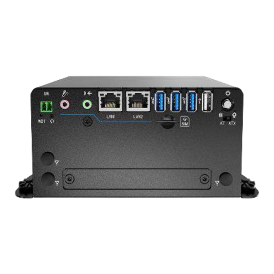
BCO-1000-EHL l User’s Manual Chapter 1: Product Introductions 1.3.2 BCO-1000-EHL-20 Front Panel • SIM card • ATX power on/off switch Used to insert a SIM card Press to power-on or power-off the system • AT/ATX mode select switch • LAN port Used to select AT or ATX power mode Used to connect the system to a local area network... - Page 17 BCO-1000-EHL l User’s Manual Chapter 1: Product Introductions 1.3.2 BCO-1000-EHL-20 Rear Panel • DC IN • Antenna hole Used to plug a DC power input with terminal Used to connect an antenna for optional block Mini-PCIe WiFi module • DisplayPort •...
-
Page 18: Bco-1000-Ehl-30
BCO-1000-EHL l User’s Manual Chapter 1: Product Introductions 1.3.3 BCO-1000-EHL-30 Front Panel • SIM card • ATX power on/off switch Used to insert a SIM card Press to power-on or power-off the system • AT/ATX mode select switch • LAN port Used to select AT or ATX power mode Used to connect the system to a local area network... - Page 19 BCO-1000-EHL l User’s Manual Chapter 1: Product Introductions 1.3.3 BCO-1000-EHL-30 Rear Panel • DC IN • Antenna hole Used to plug a DC power input with terminal Used to connect an antenna for optional block Mini-PCIe WiFi module • DisplayPort •...
-
Page 20: Mechanical Dimension
BCO-1000-EHL l User’s Manual Chapter 1: Product Introductions 1.4 Mechanical Dimensions 1.4.1 BCO-1000-EHL-10 Unit: mm... -
Page 21: Bco-1000-Ehl-20
BCO-1000-EHL l User’s Manual Chapter 1: Product Introductions 1.4.2 BCO-1000-EHL-20 Unit: mm... -
Page 22: Bco-1000-Ehl-30
BCO-1000-EHL l User’s Manual Chapter 1: Product Introductions 1.4.3 BCO-1000-EHL-30 Unit: mm... -
Page 23: Chapter 2 Switches And Connectors
Chapter 2 Switches and Connectors... -
Page 24: Switch And Connector Locations
BCO-1000-EHL l User’s Manual Chapter 2: Switches and Connectors 2.1 Switch and Connector Locations 2.1.1 Top View PWR_SW2 COM2 MIC_IN1 SODIMM1 LINE_OUT1 LAN1 COM1 LAN2 USB3_1 USB3_2 USB3_3 USB2_1 HDD_LED1 DC_IN1 PWR_SW1 PWR_LED1... -
Page 25: Bottom View
BCO-1000-EHL l User’s Manual Chapter 2: Switches and Connectors 2.1.2 Bottom View SATA1 AT_ATX1 BTB_FH1 MPCIE1 M.2_KB1 RESET1 RST_LED1 CAN1 CAN2... -
Page 26: Daughterboard View
BCO-1000-EHL l User’s Manual Chapter 2: Switches and Connectors 2.1.3 Daughter board view... -
Page 27: Connector / Switch Definition
BCO-1000-EHL l User’s Manual Chapter 2: Switches and Connectors 2.2 Connector / Switch Definition List of Connector / Switch Connector Location Definition DC_IN1 3-pin DC +9~36V Power Input Connector PWR_SW1 Power Switch PWR_SW2 Remote Power Switch DP1 - 2 Display Port COM1 - 2 RS232 / RS422 / RS485 Connector USB2_1... -
Page 28: Switch Definitions
BCO-1000-EHL l User’s Manual Chapter 2: Switches and Connectors 2.3 Switches Definitions 2.3.1 DC Power Input Connector (+9~36V) DC_IN1 Connector Type: Terminal Block 1X3 3-pin, 5.0mm pitch Switch Definition 9~36 VIN 2.3.2 Power Button PWR_SW1 Definition Definition Power Button 2.3.3 Remote Power Switch PWR_SW2 Connector Type: Terminal Block 1X2 2-pin, 3.5mm pitch Definition... - Page 29 BCO-1000-EHL l User’s Manual Chapter 2: Switches and Connectors 2.3.4 DisplayPort Connector DP1-2 Definition Definition DP_LANE0_P DP_LANE3_N DP_LANE0_N DP_LANE1_P DP_AUX_P DP_LANE1_N DP_LANE2_P DP_AUX_N DP_HPD DP_LANE2_N DP_LANE3_P DP_PWR...
- Page 30 BCO-1000-EHL l User’s Manual Chapter 2: Switches and Connectors 2.3.5 RS232 / RS422 / RS485 Connector COM1-2 Connector Type: 9-pin D-Sub RS422 / 485 Full Duplex RS485 Half Duplex RS232 Definition Definition Definition DCD2 TX2- DATA2- RxD2 TX2+ DATA2+ TxD2 RX2+ DTR2 RX2-...
- Page 31 BCO-1000-EHL l User’s Manual Chapter 2: Switches and Connectors 2.3.6 USB2.0 Connector, Type A USB2_1 Definition USB2_D2- USB2_D2+ 2.3.7 USB 3.2 Connector, Type A USB3_1-3 Definition Definition USB3_RX+ USB2_DATA1- USB2_DATA1+ USB3_TX- USB3_TX+ USB3_RX-...
- Page 32 BCO-1000-EHL l User’s Manual Chapter 2: Switches and Connectors 2.3.8 RJ45 with LEDs Port LAN1 Definition Definition LAN1_MDI0P LAN1_MDI2N LAN1_MDI0N LAN1_MDI1N LAN1_MDI1P LAN1_MDI3P LAN1_MDI2P LAN1_MDI3N Link LED Status Definition Act LED Status Definition Steady Orange 1Gbps Network Link Blinking Yellow Data Activity Steady Green 100Mbps Network Link...
- Page 33 BCO-1000-EHL l User’s Manual Chapter 2: Switches and Connectors 2.3.9 Microphone Jack (Pink) MIC_IN1 Connector Type: 5-pin Phone Jack Definition MIC_R MIC_L 2.3.10 Line-out Jack (Green) LINE_OUT1 Connector Type: 5-pin Phone Jack Definition OUT_R OUT_L PWR_LED1: Power LED Status RESET1 : Reset Button Definition Definition POWER LED+...
- Page 34 BCO-1000-EHL l User’s Manual Chapter 2: Switches and Connectors 2.3.11 AT / ATX Power Mode Switch AT_ATX1 Switch Definition 1-2 (Right) ATX Power Mode(Default) 2-3 (Left) AT Power Mode 2.3.12 SATA with Power Connector SATA1 Definition Definition SATA_TXP1 SATA_TXN1 SATA_RXN1 SATA_RXP1 +3.3V +3.3V...
- Page 35 BCO-1000-EHL l User’s Manual Chapter 2: Switches and Connectors 2.3.13 Smart FAN Connector Definition +12V FANIN FANCTL 2.3.14 CAN Bus Connector CAN 1-2 Definition CAN_H CAN_L...
- Page 36 BCO-1000-EHL l User’s Manual Chapter 2: Switches and Connectors 2.3.15 Mini PCI-Express / mSATA Socket MPCIE1 Definition Definition Definition WAKE# +3.3V +3.3V USB_DP1 +3.3V MINIPCIE RST# MINIPCIE_RXN1 +3.3V +1.5V +3.3V CLKREQ1# MINIPCIE_RXP1 USIM_VCC USIM_DATA +1.5V MINIPCIE_CLKN1 USIM_CLK SMB_CLK +1.5V MINIPCIE_CLKP1 MINIPCIE_TXN1 USIM_RST SMB_DATA...
- Page 37 BCO-1000-EHL l User’s Manual Chapter 2: Switches and Connectors 2.3.16 M.2 B Key Socket M2_KB1 Definition Definition +3.3V +3.3V +3.3V +1.8S USB2_D+ +3.3V USB2_D- +3.3V USB_RxN0 USB_RxP0 SIM_RST SIM_CLK USB_TxN0 SIM_DATA USB_TxP0 SIM_VDD PCIE_RxN0 PCIE_RxP0 PCIE_TxN0 PCIE_TxP0 PCIE_RST# REFCLK1- CLK_REQ# REFCLK1+ PCIE_WAKE# +3.3V...
- Page 38 BCO-1000-EHL l User’s Manual Chapter 2: Switches and Connectors 2.3.17 SIM Card Socket SIM1 - 2 Definition Definition UIM_PWR UIM_VPP UIM_RESET UIM_DATA UIM_CLK 2.3.18 Digital Input / Output Connector DIO1 Connector Type: Terminal Block 1X10 10-pin, 3.5mm pitch Definition Definition DC INPUT...
- Page 39 BCO-1000-EHL l User’s Manual Chapter 2: Switches and Connectors 2.3.19 RS232 / RS422 / RS485 Connector CN1 – 2 Connector Type: 9-pin D-Sub RS422 / 485 Full RS485 Half Duplex RS232 Definition Duplex Definition Definition DCD3 (DCD5) TX3- (TX5-) DATA3- (DATA5-) RxD3 (RxD5) TX3+ (TX5+) DATA3+ (DATA5+)
-
Page 40: Chapter 3 System Setup
Chapter 3 System Setup... -
Page 41: Torque Force To 3.5 Kgf Cm To Execute All The Screwing And
BCO-1000-EHL l User’s Manual Chapter 3: System Setup 3.1 Set torque force to 3.5 kgf-cm to execute all the screwing and unscrewing. In order to prevent electric shock or system damage, before removing the chassis cover, must turn off power and disconnect the unit from power source. 3.2 Removing chassis bottom cover 1. -
Page 42: Installing Sodimm
BCO-1000-EHL l User’s Manual Chapter 3: System Setup 3.3 Installing SODIMM 1. Unscrew five screws on the chassis: one screw on front panel, two screws on system left side, and two screws on system right side. 2. Hold the chassis top cover. Pull the system main body following the below direction so the top cover can be separated from it. - Page 43 BCO-1000-EHL l User’s Manual Chapter 3: System Setup 3. System main body and top cover separated. 4. Insert memory module from 45 degree direction. 5. Press the memory module vertically downward until you hear the “click” sound. Make sure the memory module is firmly in place.
-
Page 44: Installing Sata Hdd/Ssd
BCO-1000-EHL l User’s Manual Chapter 3: System Setup 3.4 Installing SATA HDD/SSD 1. Remove HDD bracket by unscrewing the four screws. 2. Lock the 2.5” HDD with HDD bracket using four screws. - Page 45 BCO-1000-EHL l User’s Manual Chapter 3: System Setup 3. Insert the entire bracket following the below direction so the SATA connector is firmly plugged into the HDD. 4. Fasten the four screws to lock the HDD bracket in place.
-
Page 46: Installing Mini Pcie Card / Msata
BCO-1000-EHL l User’s Manual Chapter 3: System Setup 3.5 Installing Mini PCIe card / mSATA 1. Place the system body upside down so you can see the 2x mini card socket. Mini PCIe 2 (CN3) can support mSATA. Mini PCIe 2 mSATA M.2 (B Key) 1. -
Page 47: Installing Antenna
BCO-1000-EHL l User’s Manual Chapter 3: System Setup 3.6 Installing antenna 1. Remove antenna hole cover on the system panel. 2. Have antenna jack penetrate through the hole. - Page 48 BCO-1000-EHL l User’s Manual Chapter 3: System Setup 3. Put on washer and fasten the nut with antenna jack. 4. Assemble the antenna and antenna jack together. 5. Attach the RF connector at the cable-end onto the communication module.
-
Page 49: Assemble Chassis Bottom Cover
BCO-1000-EHL l User’s Manual Chapter 3: System Setup 3.7 Assemble chassis bottom cover 1. Place the bottom cover according to the below direction. 2. Lock the bottom cover with the four screws. -
Page 50: Installing Sim Card
BCO-1000-EHL l User’s Manual Chapter 3: System Setup 3.8 Installing SIM card 1. SIM card socket is located on the front panel of the system. 2. Now you can insert SIM card into the socket. 3. To uninstall SIM card, simply press the installed SIM card and then the card will be pushed out. -
Page 51: Installing Din Rail Holder
BCO-1000-EHL l User’s Manual Chapter 3: System Setup 3.9 Installing DIN rail holder 1. Din rail holder is available for BCO-1000 series as optional accessories. 2. in rail holder on top of the bottom cover and lock it with two screws (M4x5L, Nylok). -
Page 52: Chapter 4 Bios Setup
Chapter 4 BIOS Setup... -
Page 53: Bios Introduction
BCO-1000-EHL l User’s Manual Chapter 4: BIOS Setup 4.1 BIOS Introduction The BIOS provides an interface to modify the configuration. When the battery is removed, all the parameters will be reset. BIOS Setup Power on the embedded system and by pressing <Del> immediately allows you to enter the setup screens. -
Page 54: Main Setup
BCO-1000-EHL l User’s Manual Chapter 4: BIOS Setup 4.2 Main Setup Press <Del> to enter BIOS CMOS Setup Utility. The Main setup screen is showed as following when the setup utility is entered. System Date/Time is set up in the Main Menu. ◼... -
Page 55: Advanced Setup
BCO-1000-EHL l User’s Manual Chapter 4: BIOS Setup 4.3 Advanced Setup... -
Page 56: Cpu Configuration
BCO-1000-EHL l User’s Manual Chapter 4: BIOS Setup 4.3.1 CPU Configuration Item Options Description When enabled, a VMM can utilize the Intel (VMX) Virtualization Disabled, additional hardware capabilities provided by Technology Enabled[Default] Virtualization Technology. All[Default] Number of cores to enable in each processor Active Processor Cores package. -
Page 57: Pch-Fw Configuration
BCO-1000-EHL l User’s Manual Chapter 4: BIOS Setup 4.3.2 PCH-FW Configuration... -
Page 58: Sata And Rst Configuration
BCO-1000-EHL l User’s Manual Chapter 4: BIOS Setup 4.3.3 SATA and RST Configuration Item Options Description Disabled, Port0 ~1 Enable or Disable SATA Port. Enabled[Default] Hard Disk Drive[Default] , Identify the SATA port is connected to Solid SATA Device Type Solid State Drive State Drive or Hard Disk Drive. -
Page 59: Trusted Computing
BCO-1000-EHL l User’s Manual Chapter 4: BIOS Setup 4.3.4 Trusted Computing Item Options Description Enable/Disable BIOS support for security device. O.S. will not show Security Enabled[Default] , Security Device Support Disabled, Device.TCG EFI protocol and INT1A interface will not be available. Schedule an Operation for the Security Device. -
Page 60: Acpi Settings
BCO-1000-EHL l User’s Manual Chapter 4: BIOS Setup 4.3.5 ACPI Settings Item Options Description Enables or Disables System ability to Disabled , Hibernate (OS/S4 Sleep State). This option Enable Hibernation Enabled[Default], may not be effective with some operating systems. Select the highest ACPI sleep state the Suspend Disabled, ACPI Sleep State system will enter when the SUSPEDN... -
Page 61: Super Io Configuration
BCO-1000-EHL l User’s Manual Chapter 4: BIOS Setup 4.3.6 Super IO Configuration This setting allows you to select options for the Super IO Configuration, and change the value of the selected option. Item Description Serial Port 1 Configuration Set Parameters of Serial Port 1 (COMA). Serial Port 2 Configuration Set Parameters of Serial Port 2 (COMB). - Page 62 BCO-1000-EHL l User’s Manual Chapter 4: BIOS Setup ◼ Serial Port 1 Configuration Item Options Description Disabled, Serial Port Enable or Disable Serial Port (COM). Enabled[Default] Auto[Default], IO=3F8h; IRQ=4; , IO=3F8h; IRQ=3,4,5,6,7,9,10,11,12; , This item allows you to change the address & Change Settings IO=2F8h;...
- Page 63 BCO-1000-EHL l User’s Manual Chapter 4: BIOS Setup ◼ Serial Port 2 Configuration Item Options Description Disabled, Serial Port Enable or Disable Serial Port (COM). Enabled[Default] Auto[Default], IO=2F8h; IRQ=3; , IO=3F8h; IRQ=3,4,5,6,7,9,10,11,12; , This item allows you to change the address & Change Settings IO=2F8h;...
- Page 64 BCO-1000-EHL l User’s Manual Chapter 4: BIOS Setup ◼ Serial Port 3 Configuration Item Options Description Disabled, Serial Port Enable or Disable Serial Port (COM). Enabled[Default] Auto[Default], IO=3E8h; IRQ=7; , IO=3E8h; IRQ=3,4,5,6,7,9,10,11,12; , This item allows you to change the address & Change Settings IO=2E8h;...
- Page 65 BCO-1000-EHL l User’s Manual Chapter 4: BIOS Setup ◼ Serial Port 4 Configuration Item Options Description Disabled, Serial Port Enable or Disable Serial Port (COM). Enabled[Default] Auto[Default], IO=2E8h; IRQ=7; , IO=3E8h; IRQ=3,4,5,6,7,9,10,11,12; , This item allows you to change the address & Change Settings IO=2E8h;...
- Page 66 BCO-1000-EHL l User’s Manual Chapter 4: BIOS Setup ◼ Serial Port 5 Configuration Item Options Description Disabled, Serial Port Enable or Disable Serial Port (COM). Enabled[Default] Auto[Default], IO=2F0h; IRQ=7; , IO=3E8h; IRQ=3,4,5,6,7,9,10,11,12; , This item allows you to change the address & Change Settings IO=2E8h;...
- Page 67 BCO-1000-EHL l User’s Manual Chapter 4: BIOS Setup ◼ Serial Port 6 Configuration Item Options Description Disabled, Serial Port Enable or Disable Serial Port (COM). Enabled[Default] Auto[Default], IO=2E0h; IRQ=7; , IO=3E8h; IRQ=3,4,5,6,7,9,10,11,12; , This item allows you to change the address & Change Settings IO=2E8h;...
-
Page 68: Hardware Monitor
BCO-1000-EHL l User’s Manual Chapter 4: BIOS Setup 4.3.7 Hardware Monitor These items display the current status of all monitored hardware devices/ components such as voltages and temperatures. Item Options Description Disabled[Default], Smart Fan Function Enabled or Disable Smart Fan Enabled... - Page 69 BCO-1000-EHL l User’s Manual Chapter 4: BIOS Setup ◼ Smart Fan Mode Configuration Item Options Description Manual Duty Mode, Fan1 SmartFan Control Smart Fan Mode Select Auto Duty-Cycle Mode[Default], Temperature 1~4 1~100 Auto fan speed control. SMART FAN IV 20~100 Duty Cycle 1~4 Auto fan speed control.
-
Page 70: Power Ign Mode
BCO-1000-EHL l User’s Manual Chapter 4: BIOS Setup 4.3.8 Power IGN Mode Item Options Description Bypass: BIOS will not control IGN Module, Bypass mode[Default] IGN Setting Write IGN: BIOS will write setting to IGN Write IGN module 10 Sec[Default] 20 Sec 30 Sec Power On Delay 40 Sec... -
Page 71: Serial Port Console Redirection
BCO-1000-EHL l User’s Manual Chapter 4: BIOS Setup 4.3.9 Serial Port Console Redirection Item Options Description Disabled[Default], These items allows you to enable or disable Console Redirection Enabled COM1 console redirection... -
Page 72: Usb Configuration
BCO-1000-EHL l User’s Manual Chapter 4: BIOS Setup 4.3.10 USB Configuration Item Options Description Enables Legacy USB support. AUTO option Enabled[Default] disables legacy support if no USB devices are Legacy USB Support Disabled connected. DISABLE option will keep USB Auto devices available only for EFI applications. -
Page 73: Network Stack Configuration
BCO-1000-EHL l User’s Manual Chapter 4: BIOS Setup 4.3.11 Network Stack Configuration Item Options Description Disabled[Default] , Network Stack Enable/Disable UEFI Network Stack. Enabled Enable/Disable IPv4 PXE boot support. If Disabled[Default] , IPv4 PXE Support disabled, IPv4 PXE boot support will not be Enabled available. -
Page 74: Chipset
BCO-1000-EHL l User’s Manual Chapter 4: BIOS Setup 4.4 Chipset This section allows you to configure and improve your system and allows you to set up some system features according to your preference. -
Page 75: System Agent (Sa) Configuration
BCO-1000-EHL l User’s Manual Chapter 4: BIOS Setup 4.4.1 System Agent (SA) Configuration Item Options Description Disabled, VT-d VT-d capability. Enabled [Default] Enable/Disable above 4GB MemoryMappedIO Above 4GB MMIO BIOS Enabled[Default] , BIOS assignment\n\nThis is enabled assignment Disabled automatically when Aperture Size is set to 2048MB. - Page 76 BCO-1000-EHL l User’s Manual Chapter 4: BIOS Setup ◼ Memory Configuration Item Options Description Dynamic[Default], 1GB, 1.25GB, Maximum Value of TOLUD. Dynamic 1.5 GB, assignment would adjust TOLUD Max TOLUD 1.75 GB, automatically based on largest MMIO length 2 GB, of installed graphic controller 2.25 GB, 2.5 GB,...
- Page 77 BCO-1000-EHL l User’s Manual Chapter 4: BIOS Setup ◼ Graphic Configuration Item Options Description GTT Size 2MB, Select the GTT Size . 4MB, 8MB[Default] Aperture Size 128MB, Select the Aperture Size. 256MB[Default] , Note : Above 4GB MMIO BIOS assignment is 512MB, automatically enabled when selecting 1024MB...
-
Page 78: Pch-Io Configuration
BCO-1000-EHL l User’s Manual Chapter 4: BIOS Setup 4.4.2 PCH-IO Configuration Item Options Description Power On, Restore AC Power Specify what state to go to when power is re- Power Off [Default] , Loss applied after a power failure (G3 state). Lase State... - Page 79 BCO-1000-EHL l User’s Manual Chapter 4: BIOS Setup ◼ PCI Express Configuration...
- Page 80 BCO-1000-EHL l User’s Manual Chapter 4: BIOS Setup ◼ PCI Express Root Port 3 /4 /5 /7 Item Options Description PCI Express Root Port Disabled, Control the PCI Express Root Port. Enabled [Default] 3 /4 /5 /7 Set the ASPM Level: Disabled [Default] , L0s, Force L0s - Force all links to L0s State,...
- Page 81 BCO-1000-EHL l User’s Manual Chapter 4: BIOS Setup ◼ USB Configuration Item Options Description Option to enable Compliance Mode. Default is XHCI Compliance Disabled [Default] , to disable Compliance Mode. Change to mode Enabled enabled for Compliance Mode testing.
- Page 82 BCO-1000-EHL l User’s Manual Chapter 4: BIOS Setup ◼ HD Audio Configuration Item Options Description Control Detection of the HD-Audio device. Disabled = HDA will be unconditionally Disabled, HD Audio disabled Enabled [Default] Enabled = HDA will be unconditionally enabled.
-
Page 83: Security
BCO-1000-EHL l User’s Manual Chapter 4: BIOS Setup 4.5 Security Security menu allow users to change administrator password and user password settings. ◼ Administrator Password This item allows you to set Administrator Password. ◼ User Password This item allows you to set User Password. - Page 84 BCO-1000-EHL l User’s Manual Chapter 4: BIOS Setup ◼ Security Boot Item Options Description Secure Boot feature is Active if Secure Boot is Enabled,Platform Key(PK) is enrolled and the Disabled [Default] , Secure Boot System is in User mode. Enabled The mode change requires platform reset Secure Boot mode options:Standard or Custom.
- Page 85 BCO-1000-EHL l User’s Manual Chapter 4: BIOS Setup ◼ Key Management Item Options Description Install factory default Secure Boot keys after Disabled [Default] , Factory Key Provision the platform reset and while the System is in Enabled Setup mode...
-
Page 86: Boot
BCO-1000-EHL l User’s Manual Chapter 4: BIOS Setup 4.6 Boot This menu allows you to setup the system boot options. Item Options Description Number of seconds to wait for setup Setup Prompt activation 1[Default] Timeout key. 65535(0xFFFF) means indefinite waiting. Bootup NumLock On[Default] , Select the Keyboard NumLock state. -
Page 87: Save & Exit
BCO-1000-EHL l User’s Manual Chapter 4: BIOS Setup 4.7 Save & Exit This setting allows users to configure the boot settings. ■ Save Changes and Reset This item allows user to reset the system after saving the changes. This item allows user to reset the system after saving the changes. -
Page 88: Appendix Wdt & Gpio
Appendix WDT & GPIO This appendix provides the sample codes of WDT (Watch Dog Timer) and GPIO (General Purpose Input/ Output). -
Page 89: Wdt Sample Code
BCO-1000-EHL l User’s Manual Appendix – WDT & GPIO WDT Sample Code WDT Setting Psuedo Code // IO Address 0xA16 is time value // IO Address 0xA15 is WDT enable and configuration Example, Set 0xA16=-0x03, 0xA15=0x31, it will reset after 3 seconds #define TimePort 0xA16 #define TimeEnablePort 0xA15... -
Page 90: Gpio Sample Code
BCO-1000-EHL l User’s Manual Appendix – WDT & GPIO GPIO Sample Code GPIO Setting IO_DO4 I/O 0xA02h Bit3 IO_DO3 I/O 0xA02h Bit2 IO_DO2 I/O 0xA02h Bit1 IO_DO1 I/O 0xA02h Bit0 IO_DI4 I/O 0xA03h Bit7 IO_DI3 I/O 0xA03h Bit6 IO_DI2 I/O 0xA03h Bit5 IO_DI1 I/O 0xA03h Bit4 The GPIO function is provided by SIO, and it can be accessed through its GPIO port. - Page 91 Premio Inc. All Rights Reserved www.premioinc.com...
Need help?
Do you have a question about the BCO-1000-EHL Series and is the answer not in the manual?
Questions and answers