Table of Contents
Advertisement
Quick Links
Models:
RED60
• Important operating
a n d m a i n t e n a n c e
instructions included.
WARNING: If the information in these
instructions is not followed exactly, a fire
or explosion may result causing property
damage, personal injury, or death.
• DO NOT store or use gasoline or other flam-
mable vapors and liquids in the vicinity of this
or any other appliance.
• What to do if you smell gas
- DO NOT try to light any appliance.
- DO NOT touch any electrical switch. DO
NOT use any phone in your building.
- Immediately call your gas supplier from a
neighbor's phone. Follow the gas supplier's
instructions.
- If you cannot reach your gas supplier, call
the fire department.
• Installation and service must be performed
by a qualified installer, service agency, or the
gas supplier.
This appliance may be installed as an OEM installation in
manufactured home (USA only) or mobile home and must be
installed in accordance with the manufacturer's instructions
and the manufactured home construction and safety standard,
Title 24 CFR, Part 3280 or Standard for Installation in Mobile
Homes, CAN/CSA Z240MH, in Canada.
This appliance is only for use with the type(s) of gas indicated
on the rating plate.
NOTICE
DO NOT DISCARD THIS MANUAL
• Read, understand and follow
these instructions for safe
installation and operation.
Heat & Glo • RED60 • 2159-900 Rev. R • 9/12
Owner's Manual
• Leave this manual with
party responsible for use
and operation.
WARNING
HOT SURFACES!
Glass and other surfaces are hot during
operation AND cool down.
Hot glass will cause burns.
• DO NOT touch glass until it is cooled
• NEVER allow children to touch glass
• Keep children away
• CAREFULLY SUPERVISE children in same room as
fireplace.
• Alert children and adults to hazards of high temperatures.
High temperatures may ignite clothing or other flammable
materials.
• Keep clothing, furniture, draperies and other flammable
materials away.
This appliance has been supplied with an integral barrier
to prevent direct contact with the fixed glass panel. DO
NOT operate the appliance with the barrier removed.
Contact your dealer or Hearth & Home Technologies if the
barrier is not present or help is needed to properly install one.
In the Commonwealth of Massachusetts installation must be
performed by a licensed plumber or gas fitter.
See Table of Contents for location of additional Commonwealth
of Massachusetts requirements.
Installation and service of this appliance should be
performed by qualified personnel. Hearth & Home
Technologies suggests NFI certified or factory trained
professionals, or technicians supervised by an NFI
certified professional.
Installation and Operation
1
Advertisement
Table of Contents
Troubleshooting

Subscribe to Our Youtube Channel
Related Manuals for Hearth & Home Heat & Glo RED60


Summary of Contents for Hearth & Home Heat & Glo RED60
- Page 1 Owner’s Manual Installation and Operation Models: RED60 NOTICE DO NOT DISCARD THIS MANUAL • Important operating • Read, understand and follow • Leave this manual with a n d m a i n t e n a n c e these instructions for safe party responsible for use instructions included.
-
Page 2: Congratulations
Read this manual before installing or operating this appliance. Please retain this owner’s manual for future reference. A. Congratulations This owner’s manual should be retained for future reference. We suggest that you keep it with your other Congratulations on selecting a Heat & Glo gas fireplace, an important documents and product manuals. -
Page 3: Table Of Contents
Safety Alert Key: • DANGER! Indicates a hazardous situation which, if not avoided will result in death or serious injury. • WARNING! Indicates a hazardous situation which, if not avoided could result in death or serious injury. • CAUTION! Indicates a hazardous situation which, if not avoided, could result in minor or moderate injury. •... - Page 4 E. Electrical Service and Repair ..... . 64 F. Junction Box Installation......64 G.
-
Page 5: Limited Lifetime Warranty
B. Limited Lifetime Warranty Hearth & Home Technologies Inc. LIMITED LIFETIME WARRANTY Hearth & Home Technologies Inc., on behalf of its hearth brands (”HHT”), extends the following warranty for HHT gas, wood, pellet, coal and electric hearth appliances that are purchased from an HHT authorized dealer. WARRANTY COVERAGE: HHT warrants to the original owner of the HHT appliance at the site of installation, and to any transferee taking ownership of the appliance at the site of installation within two years following the date of original purchase, that the HHT appliance... - Page 6 B. Limited Lifetime Warranty (continued) WARRANTY CONDITIONS: • This warranty only covers HHT appliances that are purchased through an HHT authorized dealer or distributor. A list of HHT authorized dealers is available on the HHT branded websites. • This warranty is only valid while the HHT appliance remains at the site of original installation. •...
-
Page 7: Listing And Code Approvals
Listing and Code Approvals A. Appliance Certification C. BTU Specifications Minimum Orifice Models Maximum MODEL: RED60 Input Size Input BTU/h (U.S. or Canada) BTU/h (DMS) LABORATORY: Underwriters Laboratories, Inc. (UL) TYPE: Vented Gas Fireplace Heater 44,000 31,000 (0-2000 FT) RED60 STANDARD: ANSI Z21.88b-2008 CSA 2.33a-2008 (NG) CANADA 39,500 28,000 Vented Gas Fireplace Heaters (2000-4500 FT) 43,000 35,000 This product is listed to ANSI standards for “Vented Gas (0-2000 FT) RED60 Fireplace Heaters”... -
Page 8: Requirements For The Commonwealth Of Massachusetts
Inspection Note: The following requirements reference various The state or local gas inspector of the side wall horizon- Massachusetts and national codes not contained in this tally vented gas fueled equipment shall not approve the document. installation unless, upon inspection, the inspector ob- serves carbon monoxide detectors and signage installed H. Requirements for the Commonwealth of in accordance with the provisions of 248 CMR 5.08(2)(a)1... -
Page 9: User Guide
User Guide Operating Instructions A. Gas Fireplace Safety • Install a switch lock or a wall/remote control with child protection lockout feature. WARNING • Never leave children alone near a hot fireplace, whether operating or cooling down. HOT SURFACES! Glass and other surfaces are hot during •... -
Page 10: Decorative Doors And Fronts
D. Decorative Doors and Fronts 5. Module Reset This module may lock-out under certain conditions. WARNING! Risk of Fire! Install ONLY doors or fronts When this occurs, the appliance will not ignite or approved by Hearth & Home Technologies. Unapproved respond to commands. The module will go into lock-out doors or fronts may cause fireplace to overheat. -
Page 11: For Your Safety Read Before Lighting
H. Lighting Instructions (IPI) FOR YOUR SAFETY LIGHTING READ BEFORE LIGHTING INSTRUCTIONS (IPI) WARNING: If you do not follow these instructions exactly, a fire or explosion 1. This appliance is equipped with an ignition may result causing property damage, personal injury or loss of life. device which automatically lights the burner. DO NOT try to light the burner by hand. -
Page 12: After Fireplace Is Lit
I. After Fireplace is Lit Initial Break-in Procedure • The fireplace should be run three to four hours continuously on high. • Turn the fireplace off and allow it to completely cool. • Remove fixed glass assembly. See Section 14.H. • Clean fixed glass assembly. See Section 3. •... -
Page 13: Maintenance And Service
Maintenance and Service Doors, Surrounds, Fronts Any safety screen or guard removed for servicing must be replaced prior to operating the fireplace. Frequency: Annually By: Homeowner When properly maintained, your fireplace will give you many years of trouble-free service. We recommend an- Tools needed: Protective gloves, stable work surface nual service by a qualified service technician. -
Page 14: Maintenance Tasks-Qualified Service Technician
Venting • Remove all foreign objects. Frequency: Seasonally • Verify unobstructed air circulation. Burner Ignition and Operation By: Homeowner Tools needed: Protective gloves and safety glasses. Frequency: Annually • Inspect venting and termination cap for blockage or By: Qualified Service Technician obstruction such plants, bird nests, leaves, snow, debris, Tools needed: Protective gloves, vacuum cleaner, whisk etc. -
Page 15: Installer Guide
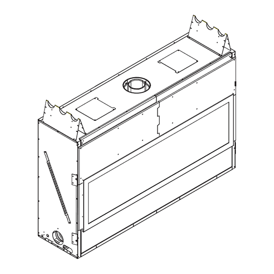
Installer Guide Getting Started A. Typical Appliance System NOTICE: Illustrations and photos reflect typical installations and are for design purposes only. Illustrations/diagrams are not drawn to scale. Actual product may vary from pictures in manual HORIZONTAL TERMINATION REFERENCES VERTICAL TERMINATION CAP (SECTION 10.H) WALL PENETRATION FRAMING (SECTION 8.B) -
Page 16: Design And Installation Considerations
B. Design and Installation Considerations D. Inspect Appliance and Components Heat & Glo direct vent gas appliances are designed to • Carefully remove the appliance and components from operate with all combustion air siphoned from outside of the packaging. the building and all exhaust gases expelled to the outside. •... -
Page 17: Framing And Clearances
Framing and Clearances A. Selecting Appliance Location NOTICE: Illustrations reflect typical installations and are FOR DESIGN PURPOSES ONLY. Illustrations/diagrams When selecting a location for the appliance it is important to are not drawn to scale. Actual installation may vary due to consider the required clearances to walls (see Figure 5.1). individual design preference. -
Page 18: Constructing The Appliance Chase
B. Constructing the Appliance Chase stuffed with unfaced insulation. If the appliance is being installed on a cement surface, a layer of plywood may be A chase is a vertical box-like structure built to enclose the placed underneath to prevent conducting cold up into the gas appliance and/or its vent system. -
Page 19: Mantel And Wall Projections
Note: For non-combustible fireplace finish material (marble, stone, etc) specifications refer to Section 13. Non-Combustible Mantels Note: All TO CEILING measurements in inches. MAX. NAILING TABS BOTH SIDES MIN. MEASUREMENTS FROM TOP EDGE OF THE FIRESCREEN DOOR ASSEMBLY Figure 5.3 Nailing Tab Locations D. Mantel and Wall Projections Figure 5.5 Minimum Vertical and Maximum Horizontal Dimensions of Non-Combustibles WARNING! Risk of Fire! Comply with all minimum clear-... -
Page 20: Termination Locations
Termination Locations A. Vent Termination Minimum Clearances 6 in. (minimum) up to 20 in. 18 in. minimum WARNING 152 mm/508 mm 457 mm 20 in. and over 0 in. minimum Fire Risk. Gas, Wood or Fuel Oil Maintain vent clearance to combustibles as Termination Cap specified. - Page 21 H or I Electrical Service = VENT TERMINAL = AIR SUPPLY INLET = AREA WHERE TERMINAL IS NOT PERMITTED = 12 inches....clearances above grade, veranda, Covered Alcove Applications porch, deck or balcony (Spaces open only on one side and with an overhang) = 9 inches....clearance to window or door that may = 6 inches ... non-vinyl sidewalls be opened, or to permanently closed 12 inches ..
-
Page 22: Vent Information And Diagrams
Vent Information and Diagrams A. Approved Pipe D. Measuring Standards This appliance is approved for use with Hearth & Home Vertical and horizontal measurements listed in the vent Technologies DVP venting systems. Refer to Section diagrams were made using the following standards. 16B for vent component information. •... -
Page 23: Installation Instructions And Venting In- Formation - Pvi-Dvp
F. Installation Instructions and Venting In- h. Clearances between the vent pipe and combustible ma- terials must be maintained at 3-inch top, 1-inch sides, formation - PVI-DVP and 1/2 inch bottom. These instructions are for appliances utilizing the PVI-DVP. i. All outer pipe joints must be sealed with high tempera- For appliances incorporating the PVK-80, see Section 7.J. -
Page 24: Framing Dimensions
Installation of Vent Pipe Framing and Clearances For information on standard procedures for venting the Note: The mounting brackets attached to the frame must appliance, refer to Section 10. be used to install the PVI-DVP. For the allowable pipe lengths and elbow combinations for Chassis Dimensions this appliance, consult Section 7.I. The PVI uses DVP pipe PVI-DVP Vertically Positioned as shown in Figure 7.4 and (8 inch) connections for both the inlet and outlet. - Page 25 If the PVI-DVP is being installed in a confined space (such Figures 7.7, 7.8, 7.9 and 7.10 show possible framing as a utility closet, mechanical room or attic space) with a techniques. total volume less than 720 cubic ft, an 8 inch by 16 inch WARNING! Risk of fire and burns! DO NOT install PVI- hole will be required directly in front of the access panel.
- Page 26 Note: AN 8 X 16 inch framed hole is required in front of the access panel. This hole may be covered with an open air louvered cover. CHASE 8 x 16 OPENING IN WALL DECORATIVE OPEN AIR COVER NOTE: COVER MUST BE AT LEAST 50% OPEN AIR.
- Page 27 SCREWS Figure 7.16 Wiring the PVI-DVP NOTICE: Electrical wiring must be done in accordance with national, provincial, and/or local electric codes. CAUTION: Risk of shock! Disconnect electrical power Figure 7.13 from fireplace/power vent before performing any mainte- The optional mounting brackets may come in handy when nance, repair, or electrical wiring.
- Page 28 INTERMITTENT PILOT IGNITOR APPLIANCE ON/OFF CONTROL SENSOR IGNITER WIRE WIRE HARNESS MALE/FEMALE WIRE ASSEMBLY HARNESS THERMO SNAP DISC HARNESS WHITE ORANGE 6VDC TRANSFORMER 8K1-PVI AUX300 MODULE WALL SWITCH JUMPER WIRE TO FAN OUTLET ON JUNCTION JUMPER ELECTRICAL ACCESS KNOCKOUT JUNCTION BOX ACCESSORY CABLE IPI WIRE...
-
Page 29: Operating Instructions
H. Maintenance CAUTION: Before performing any maintenance or repair to the power vent assembly, make sure electrical power ZIP TIE is disconnected to the fireplace. 1. Vent System: Inspect all components and connections annually. Replace, seal, or tighten pipe connections if necessary. 2. -
Page 30: Vent Diagrams
I. Vent Diagrams WARNING Fire Risk. Explosion Risk. Do NOT pack insulation or other combustibles between ceiling firestops. • ALWAYS maintain specified clearances around venting and firestop systems. • Install wall shield and ceiling firestops as specified. Failure to keep insulation or other material away from vent pipe may cause fire. Top Vent - Horizontal Termination Venting with 1 elbow Note: Must have 24 inches minimum... - Page 31 1. Top Vent - Horizontal Termination - (continued) Top Vent - Horizontal Termination Venting with 2 elbows Minimum + H Maximum Note: Must have 24 inches minimum Note: Use DVP Series vertical vent prior to attaching any 2 ft. 610 mm 50 ft. 15.2 m components only. elbow to the appliance. 3 ft. 914 mm 60 ft.
- Page 32 1. Top Vent - Horizontal Termination - (continued) Top Vent - Horizontal Termination Venting with 3 elbows Minimum Maximum Note: Use DVP Series Note: Must have 24 inches minimum components only. vertical vent prior to attaching any 2 ft. 610 mm 40 ft. 12.2 m elbow to the appliance. 3 ft. 914 mm 50 ft.
- Page 33 Top Vent - Vertical Termination No Elbows = 8 ft. Min. (2.4 m) = 50 ft. Max. (15.2 m) Figure 7.25 Vertical Vent Maximum Heat & Glo • RED60 • 2159-900 Rev. R • 9/12...
- Page 34 Top Vent - Vertical Termination Venting with 2 elbows Note: Must have 24 inches minimum Minimum + H Maximum vertical vent prior to attaching any 2 ft. 610 mm 50 ft. 15.2 m elbow to the appliance. 3 ft. 914 mm 60 ft. 18.3 m 4 ft. 1219 mm 70 ft.
- Page 35 Top Vent - Vertical Termination Venting with 3 elbows Minimum + H Maximum Note: Must have 24 inches minimum vertical vent prior to attaching any 2 ft. 610 mm 40 ft. 12.2 m elbow to the appliance. Note: Use DVP Series 3 ft. 914 mm 50 ft. 15.2 m components only.
- Page 36 Note: 1 ft. of vertical drop decreases horizontal length by 2 ft. MAXIMUM VERTICAL DROP NOTE: Maximum total vent run= Total vertical vent run + Total horizontal vent run DIRECT VENT WITH 2 FT. MINIMUM VERTICAL OFF TOP OF APPLIANCE MAX. ELBOWS MAX. TOTAL VENT RUN MAX. VERT. DROP (45° & 90°) Total V + Total H (FT.) (FT.) 26 ft. 7 ft. 16 ft. 7 ft. 16 ft.
- Page 37 Note: 1 ft. of vertical drop decreases horizontal length by 2 ft. MAXIMUM VERTICAL DROP NOTE: Maximum total vent run= Total vertical vent run + Total horizontal vent run DIRECT VENT WITH 2 FT. MINIMUM VERTICAL OFF TOP OF APPLIANCE MAX. ELBOWS MAX. TOTAL VENT RUN MAX. VERT. DROP (45° & 90°) Total V + Total H (FT.) (FT.) 34 ft. 7 ft. 22 ft. 7 ft. 22 ft.
-
Page 38: Installation Instructions And Venting Information - Pvk-80 For Red60 Model
J. Installation Instructions and Venting In- 6. CLEARANCES BETWEEN THE VENT PIPE AND COMBUSTIBLE MATERIALS MUST BE MAIN- formation - PVK-80 for RED60 Model TAINED AT 3-INCH TOP, 1-INCH SIDES, AND 1-INCH BOTTOM. These instructions are for appliances utilizing the PVK-80 for the RED60 model. For appliances incorporating the 7. - Page 39 NOTE: The PVK-80 Power Vent must terminate in a HORI- ZONTAL position. See Figure 7.31. 2. Install vent system components per planned vent run. Route the vent pipe from the fireplace to the Power Vent using the minimum number of elbows possible. 3.
-
Page 40: Installation Inspection
Note: The PVK-80 Power Vent includes a 6 1/2 foot 5-wire 8. Plug brown and red wire ends of harness routed in assembly wired into the vent cap blower motor. If this wire Step 3 onto the brown and red wires from the PVK-80 assembly will not reach the fireplace, the wires may need wiring harness. - Page 41 INTERMITTENT PILOT IGNITOR APPLIANCE ON/OFF CONTROL SENSOR IGNITER WIRE WIRE HARNESS MALE/FEMALE HARNESS WIRE ASSEMBLY THERMO SNAP DISC HARNESS WHITE ORANGE 6VDC TRANSFORMER 8K1-PVI AUX300 MODULE WALL SWITCH JUMPER WIRE TO FAN OUTLET ON JUNCTION JUMPER ELECTRICAL ACCESS KNOCKOUT JUNCTION BOX WIRE HARNESS (RED) (SHIPPED IN ACCESSORY BOX)
-
Page 42: Maintenance
OPERATING INSTRUCTIONS and carefully pull back the cable to remove the four (4) wires from the power vent assembly. After installation of the power vent, follow the operation D. With the cable loosened from the power vent assem- instructions of the fireplace. bly, remove the sheetmetal screws used to secure the 1. - Page 43 H. Slide the blower assembly out of the 10-1/2 in. diameter collar for maintenance or replacement. METAL GUIDE PLATE METAL GUIDE PLATE MUST BE IN POSITION AS SHOWN Figure 7.44 E. Secure the cap assembly to the last vent pipe section. Figure 7.42 Position the power vent assembly with the exhaust air directed downward to ensure proper operation.
- Page 44 WARNING Fire Risk. Explosion Risk. Do NOT pack insulation or other combustibles between ceiling firestops. • ALWAYS maintain specified clearances around venting and firestop systems. • Install wall shield and ceiling firestops as specified. Failure to keep insulation or other material away from vent pipe may cause fire. PVK-80 Top Vent - Horizontal Termination Venting with 1 elbow Note: Must have 24 inches minimum...
- Page 45 PVK-80 Top Vent - Horizontal Termination Venting with 2 elbows Note: Must have 24 inches minimum Minimum Maximum Note: Use DVP Series vertical vent prior to attaching any components only. 2 ft. 610 mm 20 ft. elbow to the appliance. 3 ft. 914 mm 30 ft. 9.1 m 4 ft.
- Page 46 PVK-80 Top Vent - Horizontal Termination Venting with 3 or more elbows 3 Elbows Note: Use DVP Series components only. Minimum Total V + Total H Maximum 2 ft. 610 mm 20 ft. 3 ft. 914 mm 30 ft. 9.1 m Note: Must have 24 inches minimum 4 ft. 1.2 m 40 ft. 12.1 m vertical vent prior to attaching any elbow to the appliance.
- Page 47 Note: 1 ft. of vertical drop decreases horizontal length by 2 ft. MAXIMUM VERTICAL DROP NOTE: Maximum total vent run= Total vertical vent run + Total horizontal vent run DIRECT VENT WITH 2 FT. MINIMUM VERTICAL (V ) OFF TOP OF APPLIANCE MAX. ELBOWS MAX. TOTAL VENT RUN (FT.) MAX. VERT. DROP (FT.) (45° & 90°) Total V + Total H 24 ft. 7 ft. 17 ft. 7 ft. DIRECT VENT WITH 3 FT. MINIMUM VERTICAL (V )OFF TOP OF APPLIANCE MAX. ELBOWS...
-
Page 48: Vent Clearances And Framing
Vent Clearances and Framing A. Pipe Clearances to Combustibles B. Wall Penetration Framing WARNING! Risk of Fire! Maintain air space clearance to Combustible Wall Penetration vent. DO NOT pack insulation or other combustibles: Whenever a combustible wall is penetrated, you must frame a hole for the wall shield firestop(s). The wall shield •... -
Page 49: Install The Ceiling Firestop
C. Install the Ceiling Firestop A ceiling firestop MUST be used between floors and attics. • DVP pipe only - Frame an opening 10 in. by 10 in. (254 mm by 254 mm) whenever the vent penetrates a ceiling/floor (see ATTIC ABOVE Figure 8.3). • Frame the area with the same sized lumber as used in ceiling/floor joist. -
Page 50: Install Attic Insulation Shield
D. Install Attic Insulation Shield BEND ALL TABS INWARD 90° WARNING! Fire Risk. DO NOT allow loose materials or TO MAINTAIN CLEARANCE insulation to touch vent. Hearth & Home Technologies AND PREVENT INSULATION FROM FALLING INSIDE Inc. requires the use of an attic shield. The National Fuel Gas Code ANSI Z223.1 and NFPA 54 requires an attic shield constructed of 26 gauge minimum metal that extends at least 2 in. -
Page 51: Appliance Preparation
Appliance Preparation A. Top Vent CAUTION! Risk of Cuts, Abrasions or Flying Debris. FIBERGLASS Wear protective gloves and safety glasses during instal- ROPE RING lation. Sheet metal edges are sharp. 1. Remove seal cap by lifting up and off of the starting collar. -
Page 52: Securing And Leveling The Appliance
B. Securing and Leveling the Appliance Setting the Fireplace into the Framing The left and right nailing tabs were designed as a means WARNING! Risk of Fire! Prevent contact with: to ensure the fireplace is mounted flush with the framing • Sagging or loose insulation materials. • Insulation backing or plastic Bend out all four nailing tabs. -
Page 53: Active Convection Technology
C. Active Convection Technology H1 MAX. = 8 FT. H1 + V1 + H2 = 8 FT. The fireplace appliance has been provided with an active MAX. = TWO 90° BENDS INLET CONVECTION AIR MAY BE VENTED IN convection blower. The blower is required to keep lower ANY DIRECTION,INCLUDING DOWNWARD. -
Page 54: Installing Vent Pipe (Dvp Pipe)
Installing Vent Pipe (DVP Pipe) A. Assemble Vent Sections To attach the first vent component to the starting collars of the appliance: • Lock the vent components into place by sliding the pipe section onto the collar. • Align the seam of the pipe and seam of collar to allow engagement. -
Page 55: Assemble Slip Sections
B. Assemble Slip Sections C. Secure The Vent Sections • Slide the inner flue of the slip section into the inner flue of • Vertical runs of pipe must be supported every 8 ft. (2.44 m). the pipe section and the outer flue of the slip section over •... -
Page 56: Disassemble Vent Sections
D. Disassemble Vent Sections • Level the support box both vertically and horizontally and temporarily tack it in place through the inside walls into • Rotate either section (see Figure 10.7) so the seams on the roof sheathing. both pipe sections are aligned as shown in Figure 10.8. •... -
Page 57: Install Metal Roof Flashing
F. Install Metal Roof Flashing • See minimum vent heights for various pitched roofs (Figure 10.11) to determine the length of pipe to extend CAULK through the roof. • Slide the roof flashing over the pipe sections extending through the roof as shown in Figure 10.12. HORIZONTAL OVERHANG 2 FT. -
Page 58: Install Vertical Termination Cap
H. Install Vertical Termination Cap maintaining sufficient length for a 1-1/2 in. (38 mm) overlap between heat shields. • Attach the vertical termination cap by sliding the inner • Attach the extended heat shield to either of the existing collar of the cap into the inner flue of the pipe section heat shields using the screws supplied with the extended while placing the outer collar of the cap over the outer heat shield. -
Page 59: Gas Information
Gas Information A. Fuel Conversion Note: Have the gas supply line installed in accordance with local codes, if any. If not, follow ANSI 223.1. Installation • Make sure the appliance is compatible with available gas should be done by a qualified installer approved and/or types. -
Page 60: Gas Connection
C. Gas Connection 2. Remove the base pan. It is attached with 14 screws to the interior firebox bottom and with 19 screws to the burner • Refer to Reference Section 16 for location of gas line assembly. If your appliance is a model that has the glass access in appliance. -
Page 61: Intellifire Plus Tm Ignition System Wiring
Electrical Information A. Wiring Requirements NOTICE: This appliance must be electrically wired and grounded in accordance with local codes or, in the absence of local codes, with National Electric Code ANSI/NFPA 70-latest edition or the Canadian Electric Code CSA C22.1. • Wire the appliance junction box to 110-120 VAC. This is required for proper operation of the appliance. - Page 62 INTERMITTENT PILOT IGNITOR APPLIANCE ON/OFF CONTROL SENSOR IGNITER WIRE WIRE HARNESS MALE/FEMALE WIRE ASSEMBLY HARNESS THERMO SNAP DISC HARNESS WHITE ORANGE 6VDC TRANSFORMER 8K1-PVI AUX300 MODULE WALL SWITCH JUMPER WIRE JUMPER ELECTRICAL ACCESS KNOCKOUT JUNCTION BOX TO POWER VENT IPI WIRE HARNESS HI LIMIT SWITCHES GROUND TO...
-
Page 63: Optional Led Lighting Circuit
D. Optional LED Lighting Circuit For models with LED lighting option only. LED LIGHTBAR ASSEMBLY 6 LEAD WALL CONTROL WIRE L.E.D CONTROL HARNESS LIGHT APPLIANCE CONTROL ON/OFF NOT USED FOR THIS MODEL CONTROL YELLOW ORANGE PLUG IN GREEN TO WIRE HARNESS POWER SUPPLY NOTE: The chart below show the colors produced when light control is wired and ori- entated as shown in this wiring diagram. -
Page 64: Electrical Service And Repair
E. Electrical Service and Repair G. Active Convection Blower Replacement WARNING! Risk of Shock! Label all wires prior to dis- WARNING! Risk of Shock! Label all wires prior to dis- connection when servicing controls. Wiring errors can connection when servicing controls. Wiring errors can cause improper and dangerous operation. Verify proper cause improper and dangerous operation. - Page 65 Figure 12.10 Remove Blower Figure 12.13 Removed Mounting Plate 8. Remove mounting plate from blower by removing the 10. To install new blower back into appliance, reverse the four screws that hold the blower to the plate. Save the removal procedure. Install blower assembly with the gasket for use with the new blower. See Figure 12.11 tab toward the rear of the appliance.
-
Page 66: Finishing
Finishing A. Splatter Guard The splatter guard is a piece of corrugated material used to protect the appliance during the installation process before finishing work on the whole hearth is complete. A splatter guard is factory installed on RED60 models. Splatter guards must be removed before appliance is fired. - Page 67 WARNING! Risk of Fire! Maintain specified air space Verify that the lower cover panel is installed correctly, clearances to combustibles. and that there are no screws used to attach drywall to the panel. Inadequate air space may cause overheating and fire. Ensure that the one inch back clearance and one inch side clearances are maintained.
-
Page 68: Mantel And Wall Projections
C. Mantel and Wall Projections Mantel Legs Or Wall Projections Extending Past The Face Of The Fireplace WARNING! Risk of Fire! Comply with all minimum clear- ances to combustibles as specified. Framing closer than the minimums listed must be constructed entirely of noncom- bustible materials (i.e., steel studs, concrete board, etc.) Note: For non-combustible fireplace finish material (marble, stone, etc) specifications refer to Figure 13.10 and Figure 13.11. - Page 69 WARNING! Risk of Fire! DO NOT apply combustible materials beyond the minimum clearances. Comply with all minimum clearances to combustibles as specified in 7 IN. this manual. Overlapping materials could ignite and will interfere with proper operation of doors and louvers. WARNING! Risk of Fire! DO NOT install drywall or 13-3/4 IN.
-
Page 70: Mesh Fronts
E. Mesh Fronts Ensure that no non-combustible finish materials are in- stalled within 1-11/16 inches of top and bottom and 1-3/8 WARNING! Risk of Burns! A decorative front is required inches from right and left sides of fireplace opening. This for this model. DO NOT operate this appliance without a will ensure adequate clearance for required mesh front. -
Page 71: Appliance Setup
Appliance Setup A. Remove Fixed Glass Assembly See Section 14.H. B. Remove the Shipping Materials Remove shipping materials from inside or underneath the firebox. Verify all components are with the fireplace. C. Clean the Appliance Figure 1. Selecting Flat Rocks for Pilot Cover that no rock media pieces end up in the burner lighting Clean/vacuum any sawdust that may have accumulated area. - Page 72 BURNER PORT SLOT MUST BE FREE OF ROCK MEDIA RIGHT CUT-OUT Figure 3. Place Rock Media DO NOT REMOVE CLEAR TAPE ROCK MEDIA PLACEMENT JIG Figure 6. Front Access Media Tray 7. Position the front tabs of the front access media tray toward the glass and then place in the groove of the glass frame.
-
Page 73: Porcelain Instructions
Replace side panels and secure in place by using clips on the side of the appliance. 10. The “Infinity” look of the media provides a perception that there is no glass on the appliance, while maintain- ing the sealed combustion of the appliance. Figure 1. Inner Back Panel. - Page 74 4. Place rear inside porcelain base piece. Place into bot- Installation tom of fireplace with tabs away from the burner. Center 1. Verify the correct base pan is in the appliance before from front to back. There will be a gap between the front proceeding with the porcelain installation.
-
Page 75: Service Parts
Place outside front trim base onto shelf. Place so the cutouts are in line with the outside edges of the glass frame. See Figure 14. TRIM BASE Figure 17. Outside Corner Trim Piece Installed. Service Parts Figure 14. Porcelain Trim Base Installed. 9. Install four retainer clips (included) as shown in Figure 15. Outside corner trim piece will be forced into clip on front of fireplace. - Page 76 RED60 Model With Media This kit contains the components necessary to install the porcelain on RED60 models that have media installed. Kit Contents: (1) Inner back panel. See Figure 1. (2) Inner side panels. See Figure 2. (2) Outside corner trim pieces. See Figure 3. (7) Angle tabs and (7) Sheet metal screws.
- Page 77 BEND TAB UP TAB BENT TO 90º ANGLE CLIP Figure 7. Bend Tabs Up to a 90 Degree Angle. Figure 10. Installing Outside Corner Trim Piece onto Clip. Figure 8. Bend Tabs Toward Panel 6. Install glass rocks in base of firebox according to glass media installation instructions. 7. Install glass frame assembly according to instructions in installation manual. 8. Install front media tray. 9. Install four retainer clips (included) as shown in Figure Figure 11. Installing Outside Corner Trim Piece onto Clip.
-
Page 78: Granite Instructions
Service Parts (2) Outside corner trim pieces. See Figure 3. (7) Securing tabs with (7) sheet metal screws. See Figure 4. (3) Inner front base pieces 19-3/8 inches long x 4-5/8 inches deep. See Figure 5. (3) Inner rear Base Pieces 19-3/8 inches long x 3-3/4 inches deep. - Page 79 Installation 1. Ensure fireplace is turned off and glass is cool to the touch before beginning installation. .Remove back row and sides of 1/4 inch sheet metal screws from base pan as shown in Figure 9. The screws will be located either on top of or underneath the mesh.
- Page 80 7. Place notched front base mesh granite support pieces between burner rail and front of appliance. The notched area of the granite support piece will be positioned over the pilot area and will sit securely on the base pan. Proper placement of mesh around pilot is critical to safe operation.
- Page 81 EQUAL GAP DEPTH ON GLASS FRAME TAB BOTH SIDES OF GRANITE. RETAINING TAB Figure 16. Installing Inner Front Granite Pieces. Figure 20. Attaching Retaining Tab to Glass Frame Tab. 10. Install the glass frame assembly. RETAINING TAB CONTACTS GRANITE 11. Position access panel so tabs are facing the glass as- sembly. Insert into glass frame. See Figure 17 and Figure 18. 12. Install outer front trim base onto shelf as shown in Figure 19.
- Page 82 RED60 Model With Media Tools Required: Cordless Drill This kit contains the components necessary to install the 1/4 inch hex head driver tip granite on single sided RED60 models that have media Pry Bar and Hammer for opening shipping crate. installed. Kit Contents: Installation (3) Back panel pieces 19-13/16 inches wide x 16-7/8 1.
- Page 83 GLASS FRAME TAB RETAINING TAB Figure 9. Attaching Retaining Tab to Glass Frame Tab. Figure 7. Fastening Angle Tabs to Secure Granite in Place. 4. Slide side pieces into place from the front and hold in RETAINING TAB CONTACTS GRANITE place while installing the angle tabs and screws pro- vided. Measure to be sure that the pieces are placed in the correct orientation. For the side pieces, the width is the 10 inch dimension.
-
Page 84: Sheet Metal Refractory Instructions
H. Sheet Metal Refractory Instructions 2. Install front inside base piece. Position piece into bot- tom of fireplace with tabs facing the outside edge of the A Sheet Metal Refractory Kit is available for use with the firebox. Center from front to back. There will be a gap RED60 models. - Page 85 TRIM BASE Figure 7. Outside Front Trim Base Installed. Figure 10. Outside Corner Trim Piece Installed. Service Parts 6. Install outside corner trim pieces. Outside corner trim pieces will be forced into clip on front of fireplace. See Figure 8, Figure 9 and Figure 10. CLIP Figure 8. Clip Location. Figure 11. Service Parts Diagram. ITEM DESCRIPTION COMMENTS PART NUMBER Metal Refractory Kit (RED60) SMR-60NL Panel Side No Lights 2159-237...
-
Page 86: Fixed Glass Assembly
I. Fixed Glass Assembly J. Install the Mesh WARNING! Risk of Asphyxiation! Handle fixed glass A mesh front is included with the RED60 appliance. assembly with care. Inspect the gasket to ensure it is For installation instructions, see section 13.E. undamaged and inspect the glass for cracks, chips or K. Air Shutter Setting scratches. -
Page 87: Troubleshooting
Troubleshooting With proper installation, operation, and maintenance your gas appliance will provide years of trouble-free service. If you do experience a problem, this troubleshooting guide will assist a qualified service technician in the diagnosis of a problem and the corrective action to be taken. This troubleshooting guide can only be used by a qualified service technician. Contact your dealer to arrange a service call by a qualified service technician. -
Page 88: Pvi-Dvp Troubleshooting
A. IntelliFire Plus™ Ignition System (continued) 4. (Continued) Pilot C. Module is not grounded. Verify module is securely grounded to metal chassis of appliance. lights but contin- Verify that wire harness is firmly connected to the module. ues to spark, and D. Damaged pilot assembly or con- Verify that ceramic insulator around the flame sensing rod is not main burner will not taminated flame sensing rod. -
Page 89: Reference Materials
Reference Materials A. Appliance Dimension Diagram Dimensions are actual appliance dimensions. Use for reference only. For framing dimensions and clearances refer to Section 5. STANDARD FAN DUCT ACCESS SCALE V (TYP) U (TYP) T (TYP) STANDARD GAS LINE STANDARD ACCESS HOLE ELECTRICAL ACCESS NOTE: GAS LINE ACCESS HOLE IS APPROXIMATELY 1-3/4 X 2-1/2 IN. -
Page 90: Vent Components Diagrams
B. Vent Components Diagrams Effective Length Pipe 10-1/2 in. Inches Millimeters (267 mm) 45 ° Effective DVP4 Height/Length DVP6 DVP12 4-7/8 in. DVP24 (124 mm) DVP36 10-7/8 in. (276 mm) DVP48 1219 DVP Pipe (see chart) DVP6A 3 to 6 76 to 152 DVP45 (45º... - Page 91 B. Vent Components Diagrams (continued) Note: Heat shields MUST overlap by a minimum of 1-1/2 in. (38 mm). The heat shield is designed to be used on a wall 4 in. to 7-1/4 in. (102 mm to 184 mm) thick. If wall thickness is less than 4 in. (102 mm) the existing heat shields must be field trimmed.
- Page 92 B. Vent Components Diagrams (continued) 31 in. (787 mm) 13-1/4 in. (337 mm) 24-5/8 in. (625 mm) 27-1/2 in. 24-5/8 in. (699 mm) (625 mm) 13-1/4 in. (337 mm) RF6M RF12M Roof Flashing Multi-pak Roof Flashing Multi-pak 5 in. 11-7/8 in. 5 in. 13-3/4 in.
- Page 93 B. Vent Components Diagrams (continued) 7-1/4 in. 12 in. (184 mm) 1 in. 305 mm (25 mm) 7-1/4 in. (184 mm) 12-1/2 in. (318 mm) 14 in. 5-1/4 in. (356 mm) (133 mm) DVP-TVHW VerticalTermination Cap (Highwind) 3/8 in. (10 mm) 1 in. (25 mm) 7-3/4 to 10-3/8 in.
-
Page 94: Service Parts
C. Service Parts Heat & Glo • RED60 • 2159-900 Rev. R • 9/12... - Page 95 C. Service Parts Heat & Glo • RED60 • 2159-900 Rev. R • 9/12...
- Page 96 C. Service Parts Heat & Glo • RED60 • 2159-900 Rev. R • 9/12...
- Page 97 C. Service Parts Heat & Glo • RED60 • 2159-900 Rev. R • 9/12...
-
Page 98: Contact Information
D. Contact Information Heat & Glo, a brand of Hearth & Home Technologies Inc. 7571 215th St, Lakeville, MN 55044 www.heatnglo.com Please contact your Heat & Glo dealer with any questions or concerns. For the location of your nearest Heat & Glo dealer, please visit www.heatnglo.com.
Need help?
Do you have a question about the Heat & Glo RED60 and is the answer not in the manual?
Questions and answers