Table of Contents
Advertisement
Quick Links
Advertisement
Table of Contents

Related Manuals for Supermicro AS-4124GS-TNR


Summary of Contents for Supermicro AS-4124GS-TNR
- Page 1 A+ Server AS -4124GS-TNR AS -4124GS-TNR+ USER’S MANUAL Revision 1.0c...
- Page 2 State of California, USA. The State of California, County of Santa Clara shall be the exclusive venue for the resolution of any such disputes. Supermicro's total liability for all claims will not exceed the price paid for the hardware product.
-
Page 3: About This Manual
If you have any questions, please contact our support team at: support@supermicro.com This manual may be periodically updated without notice. Please check the Supermicro website for possible updates to the manual revision level. Secure Data Deletion A secure data deletion tool designed to fully erase all data from storage devices can be found on our website: https://www.supermicro.com/about/policies/disclaimer.cfm?url=/wdl/utility/... -
Page 4: Table Of Contents
Preface Contents Chapter 1 Introduction 1.1 Overview ..........................8 1.2 Unpacking the System ......................8 1.3 System Features ........................9 1.4 Server Chassis Features ....................10 Control Panel ........................10 Front Features ........................11 Rear Features ........................12 1.5 Motherboard Layout ......................13 Quick Reference Table ......................14 Chapter 2 Server Installation 2.1 Overview ..........................17 2.2 Preparing for Setup ......................17 Choosing a Setup Location ....................17... - Page 5 A+ Server AS -4124GS-TNR/TNR+ User's Manual Memory Support and Installation ..................35 Memory Support ......................35 DIMM Module Population Sequence ................37 DIMM Installation ......................38 DIMM Removal .........................38 PCI Expansion Card Installation ..................39 Motherboard Battery ......................41 3.4 Chassis Components ......................42 Hard Drives ........................42 Hard Drive Carrier Indicators ..................44 Replacing Fans .........................45 Power Supply ........................46...
- Page 6 Preface 6.7 Boot Settings ........................95 6.8 Save & Exit .........................97 Appendix A Standardized Warning Statements for AC Systems Appendix B System Specifications...
-
Page 7: Contacting Supermicro
San Jose, CA 95131 U.S.A. Tel: +1 (408) 503-8000 Fax: +1 (408) 503-8008 Email: marketing@supermicro.com (General Information) Sales-USA@supermicro.com (Sales Inquiries) Government_Sales-USA@supermicro.com (Gov. Sales Inquiries) support@supermicro.com (Technical Support) RMA@supermicro.com (RMA Support) Webmaster@supermicro.com (Webmaster) Website: www.supermicro.com Europe Address: Super Micro Computer B.V. -
Page 8: Overview
A+ Server AS -4124GS-TNR/TNR+ User's Manual Chapter 1 Introduction 1.1 Overview This chapter provides a brief outline of the functions and features of the AS -4124GS-TNR/TNR+. The AS -4124GS-TNR/TNR+ is based on the H12DSG-O-CPU motherboard and the SC418G2TS-R4016BP chassis. Main Parts List Description Part Number Quantity... -
Page 9: System Features
Chapter 1: Introduction 1.3 System Features The following table provides you with an overview of the main features of the AS -4124GS-TNR/TNR+. Please refer to Appendix C for additional specifications. System Features Motherboard H12DSG-O-CPU Chassis SC418G2TS-R4016BP Dual AMD EPYC™ 7003 or 7002 Series processors Socket Type SP3 socket Memory... -
Page 10: Server Chassis Features
A+ Server AS -4124GS-TNR/TNR+ User's Manual 1.4 Server Chassis Features Control Panel There are two buttons located on the front of the chassis: a power on/off button and a reset button. In addition there are six LEDs. The locations of these buttons and LEDs on the control panel are described below. -
Page 11: Front Features
Chapter 1: Introduction Universal Information LED Status Description Continuously on and red An overheat condition has occurred (this may be caused by cable congestion). Blinking red (1 Hz) Fan failure: check for an inoperative fan. Blinking red (0.25 Hz) Power failure: check for an inoperative power supply. Solid blue Local UID has been activated. -
Page 12: Rear Features
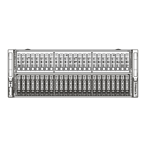
A+ Server AS -4124GS-TNR/TNR+ User's Manual Figure 1-3. Chassis Front View (AS -4124GS-TNR+) Front Chassis Features Item Feature Description Hot-swap drive bays Drive bays for hot-swap 2.5" SATA/SAS drives Hybrid hot-swap drive bays These four HDD slots are hybrid and can support SATA/SAS/NVMe drives Control panel for the server. -
Page 13: Motherboard Layout
Chapter 1: Introduction 1.5 Motherboard Layout Below is a layout of the H12DSG-O-CPU with jumper, connector and LED locations shown. See the table on the following page for descriptions. For detailed descriptions, pinout information and jumper settings, refer to Chapter 4. AIOM GPU-PWR1 ~ GPU-PWR5 JSLOT1... -
Page 14: Quick Reference Table
Solid Green: Power On Connector Description JIPMB1 4-pin External I C Header (for an IPMI card) Onboard Battery AIOM Supermicro Advanced I/O Module JOH1 Overheat LED header JSLIM-RA1/JSLIM-RA2 AIOM Input. Connection to any JSA/JSB. USB3/4 (2.0) USB3/4 (2.0) Front Side Pin Header P1-PCIE1A P1-PCIE1B Processor 1 PCIe 4.0 x8... - Page 15 Chapter 1: Introduction Connector Description JCPLD1 Complex-Programmable Logical Device (CPLD) Header Front Control Panel Header 1 I-SATA0~I-SATA3 SATA 3.0 Ports JNCSI1 NCSI Chassis Intrusion Header JPW1~JPW4 Serverboard Main Power Supply Connector GPU PWR1~10 12V 8-pin Power Connector for Riser Card GPU BP PWR1~3 12V and 5V 8-pin Power Connector for Backplane JTPM1...
- Page 16 A+ Server AS -4124GS-TNR/TNR+ User's Manual H12DSG-O-CPU AMD SP3 JS1A JS1B Micro SD NCSI CPU0 P0 [15:0] JS2A JS2B NVMe DDR4 NCSI OCP 3.0 CPU0 P1 [15:0] GMII NVMe AST2500 BMC ROM JS3A JS3B P59. 32MB VGA/COM1 IO RISER MPLINK WAKE CPU0 P2 [15:0] CPU0 USB2 [1_2]...
-
Page 17: Chapter 2 Server Installation
Chapter 2: Server Installation Chapter 2 Server Installation 2.1 Overview This chapter provides advice and instructions for mounting your system in a server rack. If your system is not already fully integrated with processors, system memory etc., refer to Chapter 4 for details on installing those specific components. Caution: Electrostatic Discharge (ESD) can damage electronic components. -
Page 18: Server Precautions
A+ Server AS -4124GS-TNR/TNR+ User's Manual • In single rack installations, stabilizers should be attached to the rack. In multiple rack in- stallations, the racks should be coupled together. • Always make sure the rack is stable before extending a server or other component from the rack. -
Page 19: Circuit Overloading
Chapter 2: Server Installation Circuit Overloading Consideration should be given to the connection of the equipment to the power supply circuitry and the effect that any possible overloading of circuits might have on overcurrent protection and power supply wiring. Appropriate consideration of equipment nameplate ratings should be used when addressing this concern. -
Page 20: Procedure For Rack Mounting
A+ Server AS -4124GS-TNR/TNR+ User's Manual 2.3 Procedure for Rack Mounting This section provides information on installing a 4U chassis into a rack unit with the rails provided. There are a variety of rack units on the market, so the assembly procedure may differ slightly. -
Page 21: Installing The Inner Rails On The Chassis
Chapter 2: Server Installation Warning: do not pick up the server with the front handles. They are designed to pull the system from a rack only. Figure 2-2. Installing the Inner Rails Note: The figure above is for illustrative purposes only. Always install servers at the bottom of the rack first. -
Page 22: Installing The Outer Rails Onto The Rack
A+ Server AS -4124GS-TNR/TNR+ User's Manual Warning: Stability hazard. The rack stabilizing mechanism must be in place, or the rack must be bolted to the floor before you slide the unit out for servicing. Failure to stabilize the rack can cause the rack to tip over. Installing the Outer Rails onto the Rack Installing the Outer Rails 1. -
Page 23: Installing The Chassis Into A Rack
Chapter 2: Server Installation Figure 2-4. Installing the Chassis into a Rack Note: Figures are for illustrative purposes only. Always install servers into racks in the lower positions first. Installing the Chassis into a Rack Installing the Chassis into a Rack: 1. -
Page 24: Removing The Chassis From The Rack
A+ Server AS -4124GS-TNR/TNR+ User's Manual Removing the Chassis from the Rack Caution! It is dangerous for a single person to off-load the heavy chassis from the rack without assistance. Be sure to have sufficient assistance supporting the chassis when removing it from the rack. -
Page 25: Chapter 3 Maintenance And Component Installation
A+ Server AS -4124GS-TNR/TNR+ User's Manual Chapter 3 Maintenance and Component Installation This chapter provides instructions on installing and replacing main system components. To prevent compatibility issues, only use components that match the specifications and/or part numbers given. Installation or replacement of most components require that power first be removed from the system. - Page 26 Chapter 3: Maintenance and Component Installation Figure 3-1. Accessing the Inside of the System Caution: Except for short periods of time, do not operate the server without the cover in place. The chassis cover must be in place to allow proper airflow and prevent overheating.
-
Page 27: Motherboard Componnets
CPU socket cap is in place and none of the socket pins are bent; otherwise, contact your retailer immediately. • Refer to the Supermicro website for updates on CPU support. Installing the Processor and Heatsink 1. Unscrew the screws holding down Force Frame in the sequence of 3-2-1. The screws are numbered on the Force Frame next to each screw hole. - Page 28 Chapter 3: Maintenance and Component Installation 2. The spring-loaded Force Frame will raise up after the last screw securing it (#1) is removed. Gently allow it to lift up to its stopping position. 3. Lift the Rail Frame up by gripping the lift tabs near the front end of the rail frame. While keeping a secure grip of the Rail Frame, lift it to a position so you can do the next step of removing the External Cap.
- Page 29 A+ Server AS -4124GS-TNR/TNR+ User's Manual 4. Remove the External Cap from the Rail Frame by pulling it upwards through the rail guides on the Rail Frame. External Cap PnP Cover Cap 5. The CPU Package is shipped from the factory with the Carrier Frame pre-assembled. Grip the handle of the Carrier Frame/CPU Package assembly from its shipping tray, and while doing so, align the flanges of the Carrier Frame onto the rails of the Rail Frame so its pins will be at the bottom when the Rail Frame is lowered later.
- Page 30 Chapter 3: Maintenance and Component Installation Note: You can only install the CPU inside the socket in one direction with the handle at the top. Make sure that it is properly inserted into the CPU socket before closing the Rail Frame plate.
- Page 31 A+ Server AS -4124GS-TNR/TNR+ User's Manual 8. Gently lower the Rail Frame down onto the socket until the latches on the Rail Frame engage with the Socket housing. and it rests in place. DO NOT force it into place!
- Page 32 Chapter 3: Maintenance and Component Installation 9. Gently lower the Force Frame down onto the Rail Frame and hold it in place until it is seated in the Socket housing. Note that the Force Frame is spring loaded and has to be held in place before it is secured.
- Page 33 A+ Server AS -4124GS-TNR/TNR+ User's Manual 11. After the Force Frame is secured and the CPU package is in place, now you must install the heatsink to the frame. Lower the heatsink down till it rests securely over the four screw holes on CPU Package on the socket frame. 12.
- Page 34 Chapter 3: Maintenance and Component Installation Un-installing the Processor and Heatsink 1. Remove the heatsink attached to the top of the CPU Package by reversing the installation procedure. 2. Clean the Thermal grease left by the heatsink on the CPU package lid to limit the risk of it contaminating the CPU package land pads or contacts in the socket housing.
-
Page 35: Memory Support And Installation
A+ Server AS -4124GS-TNR/TNR+ User's Manual Memory Support and Installation Note: Check the Supermicro website for recommended memory modules. Important: Exercise extreme care when installing or removing DIMM modules to prevent any possible damage. Memory Support The H12DSG-O-CPU supports up to 8TB of 3DS ECC DDR4-3200 RDIMM/LRDIMM memory in 32 DIMM slots. - Page 36 Chapter 3: Maintenance and Component Installation Processors and their Corresponding Memory Modules Channel Channel Channel Channel Channel Channel Channel Channel CPU# 2 DIMMS (not recommended) CPU1 CPU2 4 DIMMS (not recommended) CPU1 CPU2 8 DIMMS (not recommended) CPU1 CPU2 12 DIMMS (for 7003 CPUs only) CPU1 CPU2 16 DIMMS...
-
Page 37: Dimm Module Population Sequence
A+ Server AS -4124GS-TNR/TNR+ User's Manual DIMM Module Population Sequence When installing memory, the DIMM slots should be populated in the order shown in the table on the previous page. • The blue slots must be populated first. • Always use DDR4 DIMM modules of the same type, size and speed. •... -
Page 38: Dimm Installation
Chapter 3: Maintenance and Component Installation DIMM Installation 1. Insert the desired number of DIMMs into the memory slots in the order given on the previous page. For best performance, please use the memory modules of the same type and speed. 2. -
Page 39: Pci Expansion Card Installation
A+ Server AS -4124GS-TNR/TNR+ User's Manual PCI Expansion Card Installation The system includes a daughterboard for GPU/PCIe expansion capabilities. See Figure 3-2 for an example of the daughterboard in the system. See Figures 3-3 and 3-4 for topology for the daughterboards in AS -4124GS-TNR/TNR+ systems. Installing Expansion Cards 1. - Page 40 Chapter 3: Maintenance and Component Installation AOM-PCIE4-418N-1 XXXXXX REV:1.00 REV:1.XX DESIGNED IN USA Figure 3-4. AOM-PCIE4-418N-1-P Daughter Board...
-
Page 41: Motherboard Battery
A+ Server AS -4124GS-TNR/TNR+ User's Manual Motherboard Battery The motherboard uses non-volatile memory to retain system information when system power is removed. This memory is powered by a lithium battery residing on the motherboard. Replacing the Battery Begin by removing power from the system as described in section 3.1. 1. -
Page 42: Chassis Components
Chapter 3: Maintenance and Component Installation 3.4 Chassis Components Hard Drives The SC418G supports a total of 24 hard disk drives, which are mounted in drive carriers and reside within the hard drive bays. These drives are hot-swappable and can be removed or replaced without powering down the chassis. - Page 43 Note: Refer to the following FTP site for RAID setup guidelines: <ftp://ftp.supermicro.com/ driver/SAS/LSI/LSI_SAS_EmbMRAID_SWUG.pdf> and Supermicro’s web site for additional information < http://www.supermicro.com/support/manuals/>. Note: Enterprise level hard disk drives are recommended for use in Supermicro chassis and servers. For information on recommended HDDs, visit the Supermicro website at http://www. supermicro.com/products/nfo/files/storage/SBB-HDDCompList.pdf...
-
Page 44: Hard Drive Carrier Indicators
Chapter 3: Maintenance and Component Installation Caution: Use caution when working around the hard drive backplane. Do not touch the backplane with any metal objects and make sure no ribbon cables touch the backplane or obstruct the holes, which aid in proper airflow. Caution: Regardless of how many hard drives are installed, all drive carriers must remain in the drive bays to maintain proper airflow. -
Page 45: Replacing Fans
A+ Server AS -4124GS-TNR/TNR+ User's Manual Replacing Fans The chassis contains eight 9-cm system fans that provide cooling for the system. All fans are hot-swappable, so there is no need to power down the system when switching fans. Fan speed is controlled by a system temperature setting in IPMI. If a fan fails, the remaining fans will ramp up to full speed. -
Page 46: Power Supply
The failed power module can be replaced without powering-down the system. Replace with the same model. Replacement modules can be ordered directly from Supermicro. An amber light on the power supply is illuminated when the power is switched off. An green light indicates that the power supply is operating. -
Page 47: Chapter 4 Motherboard Connections
Chapter 4: Motherboard Connections Chapter 4 Motherboard Connections This section describes the connections on the motherboard and provides pinout definitions. Note that depending on how the system is configured, not all connections are required. The LEDs on the motherboard are also described here. A serverboard layout indicating component locations may be found in Chapter 1. -
Page 48: Front Control Panel
JF1 contains header pins for various buttons and indicators that are normally located on a control panel at the front of the chassis. These connectors are designed specifically for use with Supermicro chassis. See the figure below for the descriptions of the front control panel buttons and LED indicators. -
Page 49: Reset Button
Note: UID can also be triggered via IPMI on the serverboard. For more information on IPMI, please refer to the IPMI User's Guide posted on our website at http://www.supermicro.com. UID LED Pin Definitions (JF1) - Page 50 A+ Server AS -4124GS-TNR/TNR+ User's Manual NIC1/NIC2 (LAN1/LAN2) The NIC (Network Interface Controller) LED connection for LAN port 1 is located on pins 11 and 12 of JF1, and the LED connection for LAN Port 2 is on Pins 9 and 10. Attach the NIC LED cables here to display network activity.
-
Page 51: Ports, Connectors And Headers
Chapter 4: Motherboard Connections 4.3 Ports, Connectors and Headers Rear I/O Ports See the figure below for the locations and descriptions of the various I/O ports on the rear of the motherboard. Figure 4-2. Rear I/O Ports Rear I/O Ports Pin# Definition Pin# Definition... -
Page 52: Universal Serial Bus (Usb) Ports
(Note: UID can also be triggered via IPMI on the motherboard. For more information, please refer to the IPMI User's Guide posted on our website at http://www.supermicro.com.) UID Switch Pin Definitions... -
Page 53: Chassis Intrusion
It enables the motherboard to deny access if the TPM associated with the hard drive is not installed in the system. Please go to the following link for more information on TPM: http://www.supermicro.com/ manuals/other/TPM.pdf. Trusted Platform Module Header... - Page 54 A+ Server AS -4124GS-TNR/TNR+ User's Manual Fan Headers There are eight fan headers on the motherboard. These are 4-pin fan headers; pins 1-3 are backward compatible with traditional 3-pin fans. The onboard fan speeds are controlled by Fan Mode in the BMC. When using Fan Mode setting, please use all 4-pin fans. Fan Header Pin Definitions Pin#...
-
Page 55: Jumpers
Chapter 4: Motherboard Connections 4.4 Jumpers Explanation of Jumpers To modify the operation of the motherboard, jumpers are used to choose between optional settings. Jumpers create shorts between two pins to change the function associated with it. Pin 1 is identified with a square solder pad on the printed circuit board. See the motherboard layout page for jumper locations. -
Page 56: Led Indicators
A+ Server AS -4124GS-TNR/TNR+ User's Manual Watch Dog JWD1 controls the Watch Dog function. Watch Dog is a monitor that can reboot the system when a software application hangs. Jumping pins 1-2 will cause Watch Dog to reset the system if an application hangs. Jumping pins 2-3 will generate a non-maskable interrupt signal for the application that hangs. - Page 57 Chapter 4: Motherboard Connections BMC Heartbeat LED A BMC Heartbeat LED is located at LED2 on the serverboard. When LED2 is blinking, BMC functions normally. See the table below for more information. BMC Heartbeat LED States Color State Definition Green Solid On BMC is not ready.
-
Page 58: Chapter 5 Software
If you will be using RAID, you must configure RAID settings before installing the Windows OS and the RAID driver. Refer to the RAID Configuration User Guides posted on our website at www.supermicro.com/support/manuals. Installing the OS 1. Create a method to access the MS Windows installation ISO file. That might be a DVD, perhaps using a USB flash or media drive, or the IPMI KVM console. - Page 59 Chapter 5: Software Figure 5-2. Load Driver Link To load the driver, browse the USB flash drive for the proper driver files. • For RAID, choose the SATA/sSATA RAID driver indicated then choose the storage drive on which you want to install it. •...
-
Page 60: Driver Installation
The Supermicro website contains drivers and utilities for your system at https://www. supermicro.com/wftp/driver. Some of these must be installed, such as the chipset driver. After accessing the website, go into the CDR_Images (in the parent directory of the above link) and locate the ISO file for your motherboard. Download this file to to a USB flash or media drive. -
Page 61: Superdoctor ® 5
5.3 SuperDoctor ® The Supermicro SuperDoctor 5 is a program that functions in a command-line or web-based interface for Windows and Linux operating systems. The program monitors such system health information as CPU temperature, system voltages, system power consumption, fan speed, and provides alerts via email or Simple Network Management Protocol (SNMP). -
Page 62: Ipmi
The H12DSG-O-CPU supports the Intelligent Platform Management Interface (IPMI). IPMI is used to provide remote access, monitoring and management. There are several BIOS settings that are related to IPMI. For general documentation and information on IPMI, please visit our website at: http://www.supermicro.com/products/nfo/IPMI.cfm. -
Page 63: Appendix A: Warning Statements
Supermicro's Technical Support department for assistance. Only certified technicians should attempt to install or configure components. Read this appendix in its entirety before installing or configuring components in the Supermicro chassis. These warnings may also be found on our website at http://www.supermicro.com/about/... -
Page 64: Main Setup
Appendix A: Warning Statements Warnung WICHTIGE SICHERHEITSHINWEISE Dieses Warnsymbol bedeutet Gefahr. Sie befinden sich in einer Situation, die zu Verletzungen führen kann. Machen Sie sich vor der Arbeit mit Geräten mit den Gefahren elektrischer Schaltungen und den üblichen Verfahren zur Vorbeugung vor Unfällen vertraut. Suchen Sie mit der am Ende jeder Warnung angegebenen Anweisungsnummer nach der jeweiligen Übersetzung in den übersetzten Sicherheitshinweisen, die zusammen mit diesem Gerät ausgeliefert wurden. -
Page 65: Installation Instructions
Appendix A: Warning Statements . ٌ ا ك ً ف حالة و ٌ يك أى تتسبب ف اصابة جسذ ة ٌ هذا الزهز ع ٌ خطز !تحذ ز قبل أى تعول عىل أي هعذات،يك عىل علن بالوخاطز ال ا ٌجوة عي الذوائز ٍ... -
Page 66: Advanced
Appendix A: Warning Statements Warnung Vor dem Anschließen des Systems an die Stromquelle die Installationsanweisungen lesen. ¡Advertencia! Lea las instrucciones de instalación antes de conectar el sistema a la red de alimentación. Attention Avant de brancher le système sur la source d'alimentation, consulter les directives d'installation. .יש... - Page 67 Appendix A: Warning Statements Warnung Dieses Produkt ist darauf angewiesen, dass im Gebäude ein Kurzschluss- bzw. Überstromschutz installiert ist. Stellen Sie sicher, dass der Nennwert der Schutzvorrichtung nicht mehr als: 250 V, 20 A beträgt. ¡Advertencia! Este equipo utiliza el sistema de protección contra cortocircuitos (o sobrecorrientes) del edificio.
- Page 68 Appendix A: Warning Statements Power Disconnection Warning Warning! The system must be disconnected from all sources of power and the power cord removed from the power supply module(s) before accessing the chassis interior to install or remove system components (except for hot-swap components). 電源切断の警告...
-
Page 69: Equipment Installation
Appendix A: Warning Statements אזהרה מפני ניתוק חשמלי !אזהרה יש לנתק את המערכת מכל מקורות החשמל ויש להסיר את כבל החשמלי מהספק .לפני גישה לחלק הפנימי של המארז לצורך התקנת או הסרת רכיבים يجب فصم اننظاو من جميع مصادر انطاقت وإ ز انت سهك انكهرباء من وحدة امداد انطاقت... - Page 70 Appendix A: Warning Statements Attention Seul le personnel autorisé et le personnel de maintenance qualifié doivent être autorisés à installer, remplacer ou entretenir cet équipement.. !אזהרה .יש לאפשר רק צוות מורשה ואנשי שירות מוסמכים להתקין, להחליף או לטפל בציוד זה .ينبغي...
- Page 71 Appendix A: Warning Statements Warnung Diese Einheit ist zur Installation in Bereichen mit beschränktem Zutritt vorgesehen. Der Zutritt zu derartigen Bereichen ist nur mit einem Spezialwerkzeug, Schloss und Schlüssel oder einer sonstigen Sicherheitsvorkehrung möglich. ¡Advertencia! Esta unidad ha sido diseñada para instalación en áreas de acceso restringido. Sólo puede obtenerse acceso a una de estas áreas mediante la utilización de una herramienta especial, cerradura con llave u otro medio de seguridad.
-
Page 72: Battery Handling
Appendix A: Warning Statements Battery Handling CAUTION: There is risk of explosion if the battery is replaced by an incorrect type. Replace the battery only with the same or equivalent type recommended by the manu- facturer. Dispose of used batteries according to the manufacturer's instructions 電池の取り扱い... - Page 73 Appendix A: Warning Statements .هناك خطر االنفجار إذا تم استبدال البطارية بنوع غري صحيح اسحبذال البطارية فقط بنفس النىع أو ما يعادلها مام أوصث به الرشمة املصنعة جخلص من البطاريات املسحعملة وفقا لحعليامت الرشمة الصانعة 경고! 배터리를 잘못된 종류로 교체하면 폭발의 위험이 있습니다. 기존 배터리와 동일하거나 제조 사에서...
- Page 74 Appendix A: Warning Statements ¡Advertencia! Puede que esta unidad tenga más de una conexión para fuentes de alimentación. Para cortar por completo el suministro de energía, deben desconectarse todas las conexiones. Attention Cette unité peut avoir plus d'une connexion d'alimentation. Pour supprimer toute tension et tout courant électrique de l'unité, toutes les connexions d'alimentation doivent être débranchées.
- Page 75 Appendix A: Warning Statements Backplane Voltage Warning! Hazardous voltage or energy is present on the backplane when the system is operating. Use caution when servicing. バックプレーンの電圧 システムの稼働中は危険な電圧または電力が、 バックプレーン上にかかっています。 修理する際には注意く ださい。 警告 当系统正在进行时,背板上有很危险的电压或能量,进行维修时务必小心。 警告 當系統正在進行時,背板上有危險的電壓或能量,進行維修時務必小心。 Warnung Wenn das System in Betrieb ist, treten auf der Rückwandplatine gefährliche Spannungen oder Energien auf.
- Page 76 Appendix A: Warning Statements هناك خطز مه التيار الكهزبايئ أوالطاقة املىجىدة عىل اللىحة عندما يكىن النظام يعمل كه حذ ر ا عند خدمة هذا الجهاس 경고! 시스템이 동작 중일 때 후면판 (Backplane)에는 위험한 전압이나 에너지가 발생 합니다. 서비스 작업 시 주의하십시오. Waarschuwing Een gevaarlijke spanning of energie is aanwezig op de backplane wanneer het systeem in gebruik is.
-
Page 77: Product Disposal
Appendix A: Warning Statements תיאום חוקי החשמל הארצי !אזהרה .התקנת הציוד חייבת להיות תואמת לחוקי החשמל המקומיים והארציים تركيب املعدات الكهربائية يجب أن ميتثل للقىاويه املحلية والىطىية املتعلقة بالكهرباء 경고! 현 지역 및 국가의 전기 규정에 따라 장비를 설치해야 합니다. Waarschuwing Bij installatie van de apparatuur moet worden voldaan aan de lokale en nationale elektriciteitsvoorschriften. - Page 78 Appendix A: Warning Statements Attention La mise au rebut ou le recyclage de ce produit sont généralement soumis à des lois et/ou directives de respect de l'environnement. Renseignez-vous auprès de l'organisme compétent. סילוק המוצר !אזהרה .סילוק סופי של מוצר זה חייב להיות בהתאם להנחיות וחוקי המדינה التخلص...
- Page 79 Appendix A: Warning Statements Warnung Gefährlich Bewegende Teile. Von den bewegenden Lüfterblätter fern halten. Die Lüfter drehen sich u. U. noch, wenn die Lüfterbaugruppe aus dem Chassis genommen wird. Halten Sie Finger, Schraubendreher und andere Gegenstände von den Öffnungen des Lüftergehäuses entfernt.
- Page 80 Verbindungskabeln, Stromkabeln und/oder Adapater, die Ihre örtlichen Sicherheitsstandards einhalten. Der Gebrauch von anderen Kabeln und Adapter können Fehlfunktionen oder Feuer verursachen. Die Richtlinien untersagen das Nutzen von UL oder CAS zertifizierten Kabeln (mit UL/CSA gekennzeichnet), an Geräten oder Produkten die nicht mit Supermicro gekennzeichnet sind.
- Page 81 .قيرح وأ لطع يف ببستي دق ىرخأ تالوحمو تالباك يأ مادختسا .ميلسلا سباقلاو لصوملا مجح لبق نم ةدمتعملا تالباكلا مادختسا تادعملاو ةيئابرهكلا ةزهجألل ةمالسلا نوناق رظحيUL وأCSA ( ةمالع لمحت يتلاوUL/CSA) لبق نم ةددحملاو ةينعملا تاجتنملا ريغ ىرخأ تادعم يأ عمSupermicro.
- Page 82 사항을 준수하여 제공되거나 지정된 연결 혹은 구매 케이블, 전원 케이블 및 AC 어댑터를 사용하십시오. 다른 케이블이나 어댑터를 사용하면 오작동이나 화재가 발생할 수 있습니다. 전기 용품 안전법은 UL 또는 CSA 인증 케이블 (코드에 UL / CSA가 표시된 케이블)을 Supermicro 가 지정한 제품 이외의 전기 장치에 사용하는 것을 금지합니다. Stroomkabel en AC-Adapter...
- Page 83 Supermicro's Technical Support department for assistance. Only certified technicians should attempt to install or configure components. Read this appendix in its entirety before installing or configuring components in the Supermicro chassis. These warnings may also be found on our website at http://www.supermicro.com/about/...
- Page 84 Appendix A: Standardized Warning Statements Warnung WICHTIGE SICHERHEITSHINWEISE Dieses Warnsymbol bedeutet Gefahr. Sie befinden sich in einer Situation, die zu Verletzungen führen kann. Machen Sie sich vor der Arbeit mit Geräten mit den Gefahren elektrischer Schaltungen und den üblichen Verfahren zur Vorbeugung vor Unfällen vertraut. Suchen Sie mit der am Ende jeder Warnung angegebenen Anweisungsnummer nach der jeweiligen Übersetzung in den übersetzten Sicherheitshinweisen, die zusammen mit diesem Gerät ausgeliefert wurden.
- Page 85 A+ Server AS -4124GS-TNR/TNR+ User's Manual . ٌ ا ك ً ف حالة و ٌ يك أى تتسبب ف اصابة جسذ ة ٌ هذا الزهز ع ٌ خطز !تحذ ز قبل أى تعول عىل أي هعذات،يك عىل علن بالوخاطز ال ا ٌجوة عي الذوائز ٍ...
- Page 86 Appendix A: Standardized Warning Statements Warnung Vor dem Anschließen des Systems an die Stromquelle die Installationsanweisungen lesen. ¡Advertencia! Lea las instrucciones de instalación antes de conectar el sistema a la red de alimentación. Attention Avant de brancher le système sur la source d'alimentation, consulter les directives d'installation. .יש...
-
Page 87: Ipmi
A+ Server AS -4124GS-TNR/TNR+ User's Manual Warnung Dieses Produkt ist darauf angewiesen, dass im Gebäude ein Kurzschluss- bzw. Überstromschutz installiert ist. Stellen Sie sicher, dass der Nennwert der Schutzvorrichtung nicht mehr als: 250 V, 20 A beträgt. ¡Advertencia! Este equipo utiliza el sistema de protección contra cortocircuitos (o sobrecorrientes) del edificio. - Page 88 Appendix A: Standardized Warning Statements Power Disconnection Warning Warning! The system must be disconnected from all sources of power and the power cord removed from the power supply module(s) before accessing the chassis interior to install or remove system components. 電源切断の警告...
-
Page 89: Event Logs
A+ Server AS -4124GS-TNR/TNR+ User's Manual אזהרה מפני ניתוק חשמלי !אזהרה יש לנתק את המערכת מכל מקורות החשמל ויש להסיר את כבל החשמלי מהספק .לפני גישה לחלק הפנימי של המארז לצורך התקנת או הסרת רכיבים يجب فصم اننظاو من جميع مصادر انطاقت وإ ز انت سهك انكهرباء من وحدة امداد انطاقت... - Page 90 Appendix A: Standardized Warning Statements Attention Il est vivement recommandé de confier l'installation, le remplacement et la maintenance de ces équipements à des personnels qualifiés et expérimentés. !אזהרה .צוות מוסמך בלבד רשאי להתקין, להחליף את הציוד או לתת שירות עבור הציוד واملدربيه...
-
Page 91: Security Settings
A+ Server AS -4124GS-TNR/TNR+ User's Manual Warnung Diese Einheit ist zur Installation in Bereichen mit beschränktem Zutritt vorgesehen. Der Zutritt zu derartigen Bereichen ist nur mit einem Spezialwerkzeug, Schloss und Schlüssel oder einer sonstigen Sicherheitsvorkehrung möglich. ¡Advertencia! Esta unidad ha sido diseñada para instalación en áreas de acceso restringido. Sólo puede obtenerse acceso a una de estas áreas mediante la utilización de una herramienta especial, cerradura con llave u otro medio de seguridad. - Page 92 Appendix A: Standardized Warning Statements Battery Handling Warning! There is the danger of explosion if the battery is replaced incorrectly. Replace the battery only with the same or equivalent type recommended by the manufacturer. Dispose of used batteries according to the manufacturer's instructions 電池の取り扱い...
- Page 93 A+ Server AS -4124GS-TNR/TNR+ User's Manual هناك خطر من انفجار يف حالة اسحبذال البطارية بطريقة غري صحيحة فعليل اسحبذال البطارية فقط بنفس النىع أو ما يعادلها مام أوصث به الرشمة املصنعة جخلص من البطاريات املسحعملة وفقا لحعليامت الرشمة الصانعة 경고! 배터리가...
- Page 94 Appendix A: Standardized Warning Statements ¡Advertencia! Puede que esta unidad tenga más de una conexión para fuentes de alimentación. Para cortar por completo el suministro de energía, deben desconectarse todas las conexiones. Attention Cette unité peut avoir plus d'une connexion d'alimentation. Pour supprimer toute tension et tout courant électrique de l'unité, toutes les connexions d'alimentation doivent être débranchées.
- Page 95 A+ Server AS -4124GS-TNR/TNR+ User's Manual Backplane Voltage Warning! Hazardous voltage or energy is present on the backplane when the system is operating. Use caution when servicing. バックプレーンの電圧 システムの稼働中は危険な電圧または電力が、 バックプレーン上にかかっています。 修理する際には注意く ださい。 警告 当系统正在进行时,背板上有很危险的电压或能量,进行维修时务必小心。 警告 當系統正在進行時,背板上有危險的電壓或能量,進行維修時務必小心。 Warnung Wenn das System in Betrieb ist, treten auf der Rückwandplatine gefährliche Spannungen oder Energien auf.
- Page 96 Appendix A: Standardized Warning Statements هناك خطز مه التيار الكهزبايئ أوالطاقة املىجىدة عىل اللىحة عندما يكىن النظام يعمل كه حذ ر ا عند خدمة هذا الجهاس 경고! 시스템이 동작 중일 때 후면판 (Backplane)에는 위험한 전압이나 에너지가 발생 합니다. 서비스 작업 시 주의하십시오. Waarschuwing Een gevaarlijke spanning of energie is aanwezig op de backplane wanneer het systeem in gebruik is.
- Page 97 A+ Server AS -4124GS-TNR/TNR+ User's Manual תיאום חוקי החשמל הארצי !אזהרה .התקנת הציוד חייבת להיות תואמת לחוקי החשמל המקומיים והארציים تركيب املعدات الكهربائية يجب أن ميتثل للقىاويه املحلية والىطىية املتعلقة بالكهرباء 경고! 현 지역 및 국가의 전기 규정에 따라 장비를 설치해야 합니다. Waarschuwing Bij installatie van de apparatuur moet worden voldaan aan de lokale en nationale elektriciteitsvoorschriften.
-
Page 98: Hot Swap Fan Warning
Appendix A: Standardized Warning Statements Attention La mise au rebut ou le recyclage de ce produit sont généralement soumis à des lois et/ou directives de respect de l'environnement. Renseignez-vous auprès de l'organisme compétent. סילוק המוצר !אזהרה .סילוק סופי של מוצר זה חייב להיות בהתאם להנחיות וחוקי המדינה التخلص... - Page 99 A+ Server AS -4124GS-TNR/TNR+ User's Manual Warnung Gefährlich Bewegende Teile. Von den bewegenden Lüfterblätter fern halten. Die Lüfter drehen sich u. U. noch, wenn die Lüfterbaugruppe aus dem Chassis genommen wird. Halten Sie Finger, Schraubendreher und andere Gegenstände von den Öffnungen des Lüftergehäuses entfernt.
-
Page 100: Power Cable And Ac Adapter
Verbindungskabeln, Stromkabeln und/oder Adapater, die Ihre örtlichen Sicherheitsstandards einhalten. Der Gebrauch von anderen Kabeln und Adapter können Fehlfunktionen oder Feuer verursachen. Die Richtlinien untersagen das Nutzen von UL oder CAS zertifizierten Kabeln (mit UL/CSA gekennzeichnet), an Geräten oder Produkten die nicht mit Supermicro gekennzeichnet sind. - Page 101 .قيرح وأ لطع يف ببستي دق ىرخأ تالوحمو تالباك يأ مادختسا .ميلسلا سباقلاو لصوملا مجح لبق نم ةدمتعملا تالباكلا مادختسا تادعملاو ةيئابرهكلا ةزهجألل ةمالسلا نوناق رظحيUL وأCSA ( ةمالع لمحت يتلاوUL/CSA) لبق نم ةددحملاو ةينعملا تاجتنملا ريغ ىرخأ تادعم يأ عمSupermicro.
- Page 102 사항을 준수하여 제공되거나 지정된 연결 혹은 구매 케이블, 전원 케이블 및 AC 어댑터를 사용하십시오. 다른 케이블이나 어댑터를 사용하면 오작동이나 화재가 발생할 수 있습니다. 전기 용품 안전법은 UL 또는 CSA 인증 케이블 (코드에 UL / CSA가 표시된 케이블)을 Supermicro 가 지정한 제품 이외의 전기 장치에 사용하는 것을 금지합니다. Stroomkabel en AC-Adapter...
-
Page 103: System Specifications
Appendix B: System Specifications Appendix B System Specifications Processors Dual AMD EPYC™ 7003 or 7002 Series processors in SP3 sockets Note: Please refer to the motherboard specifications pages on our website for updates to supported processors. Chipset BIOS AMI 32Mb SPI Flash ROM Memory Up to 8TB of 3DS ECC DDR4-3200 RDIMM/LRDIMM memory in 32 DIMM slots. - Page 104 A+ Server AS -4124GS-TNR/TNR+ User's Manual Operating Environment Operating Temperature: 10º to 35º C (50º to 95º F) Non-operating Temperature: -40º to 60º C (-40º to 140º F) Operating Relative Humidity: 8% to 90% (non-condensing) Non-operating Relative Humidity: 5 to 95% (non-condensing) Regulatory Compliance Electromagnetic Emissions: FCC Class A, EN 55032 Class A, EN 61000-3-2/3-3, CISPR 32 Class A Electromagnetic Immunity: EN 55024/CISPR 24, (EN 61000-4-2, EN 61000-4-3, EN 61000-4-4, EN 61000-4-5, EN 61000-4-6,...
Need help?
Do you have a question about the AS-4124GS-TNR and is the answer not in the manual?
Questions and answers