Table of Contents
Advertisement
Quick Links
Advertisement
Table of Contents

Related Manuals for Supermicro AS-2025HS-TNR


Summary of Contents for Supermicro AS-2025HS-TNR
- Page 1 WEEE DISASSEMBLY INSTRUCTIONS SUPERMICRO AS -2025HS-TNR ENCLOSURE Abstract This document provides clear guidance for end-of-life recyclers on how to identify and disassemble reportable materials in compliance with the Waste Electrical and Electronic Equipment (WEEE) directive.
-
Page 2: Table Of Contents
Table of Contents Product Views ............................3 Reportable Materials on AS -2025HS-TNR ....................4 Disassemble Instructions .......................... 5 3.3 Step-by-Step Disassembly Instructions ....................8 Removing Cable and Chassis Top Cover ..................8 Removing Hard Disk Drive (HDD) / Solid State Drive (SDD) ............9 Removing Power Supply ...................... -
Page 3: Product Views
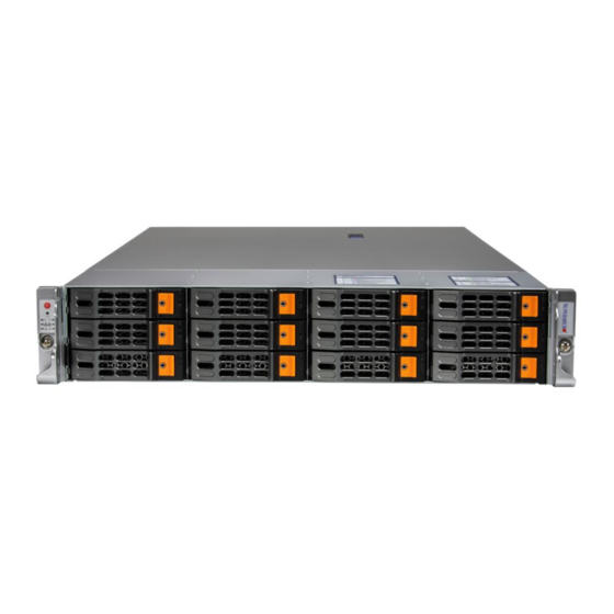
1. Product Views Front view Rear view Product construct view... -
Page 4: Reportable Materials On As -2025Hs-Tnr
2. Reportable Materials on AS -2025HS-TNR According to Article 8(2) and Annex VII of WEEE directive 2012/19/EU, Below materials and components should be selectively treated. Description Notes Quantity Printed Circuit Boards (PCB) or 2.4,3.5,4.1,6.2,7.2,8.1,9.1, With a surface greater than 10 sq cm Printed Circuit Assemblies (PCA) 10.1,10.2,10.3,11.1,12.2 All types, including standard alkaline... -
Page 5: Disassemble Instructions
3. Disassemble Instructions The intent of this document is to provide guidance to recyclers on the presence of materials and components at the product / family level, as required by the EU WEEE Directive 2012/10/EU. This document should also help direct recyclers to proper methods for removing parts and general product disassembly instructions. - Page 6 Chassis Backplane Plastics Cover Screw Motherboard Cable Battery Power Supply Power Enclosure*2 Screw *2 Set Power Supply Module*2...
- Page 7 Storage Card and CPU Heat Sink *2 Processor *2 SSD *2set DIMM *2set Power Cable M.2 *2 AIOM, Add-on Card...
-
Page 8: Step-By-Step Disassembly Instructions
3.3 Step-by-Step Disassembly Instructions 1. Removing Cable and Chassis Top Cover 1. Use the operating system to power down the system. 2. After the system has completely shut-down, disconnect the power cords from the power supply modules. 3. Remove all cables/ unit from the server IO port. 4. -
Page 9: Removing Hard Disk Drive (Hdd) / Solid State Drive (Sdd)
2. Removing Hard Disk Drive (HDD) / Solid State Drive (SDD) 1. Press the release button on the drive carrier, which will extend the drive carrier handle. 2. Use the drive carrier handle to pull the drive out of the chassis. 3. -
Page 10: Removing Power Supply
5. Use a cross screwdriver to remove drive enclosure 6. Use a cross screwdriver to remove screws and lift off the PCB Description Dummy Tray HDD/ SSD Hard Drive Enclosure Hard Drive PCB 3. Removing Power Supply 1. Press the release tab on the power supply. 2. -
Page 11: Removing Backplane
Remove the screw from the enclosure 5. Disconnected to the fan and lift the main board from the chassis by hand Use a flathead screwdriver to cut the capacitor adhesive and pin solder. Description Power Supply Power Enclosure Fan Cable Power Module PCB Capacitor 4. -
Page 12: Removing Fan
5. Removing Fan 1. Disconnect the chassis fan from the motherboard fan connectors and lift fans out of chassis. Description Cooling Fans 6. Removing the Air shroud, Riser, and the Riser Bracket 1. Lift the air shroud out of the chassis by hand 2. -
Page 13: Removing Processor
Riser Cards Riser Bracket Removing Processor 1. Remove the heatsink attached to the top of the CPU package by reversing the installation procedure. 2. Clean the thermal grease left by the heatsink on the CPU package lid to limit the risk of it contaminating the CPU package land pads or contacts in the socket housing. -
Page 14: Removing Dimm
Heat Sink Processor 8. Removing DIMM 1. Hand press both release tabs on the ends of the DIMM module to unlock it 2. Once the DIMM module is loose, remove it from the memory slot Description DIMM 9. Removing the M.2 1. -
Page 15: Removing Motherboard
10.1 3. Remove add on module sliding into keyhole standoffs *2 (red), unscrew with thumbscrew (yellow). 10.2 4. Find the motherboard JTPM1 connector and pull up the TPM 10.3 Description 10.1 AIOM PCB 10.2 Add-On Module 10.3 11. Removing Motherboard... - Page 16 1. Remove screws, lift out motherboard 2. Push aside the small clamp that covers the edge of the battery. When the battery is released, lift it out of the holder. 3. When the motherboard is removed, the node enclosure can be recycled 11.2 11.1 Description...
Need help?
Do you have a question about the AS-2025HS-TNR and is the answer not in the manual?
Questions and answers