Advertisement
Quick Links
A
B
5
6
1
2
7
8
E
E.2
E.1
o
R 0,5 mm
max. 15
EN – ATTENTION: Read and understand this user manual before using this equipment. Work requiring the use
of this equipment is dangerous. The user is obliged to follow this manual and is responsible for the correct use of
the equipment. Misuse of the equipment can lead to injury or death. If you have any problems understanding this
manual, please contact the equipment manufacturer.
A. DESCRIPTION. The LINOSTOPII ED guided type fall arrester with flexible guide is a component of personal
protective equipment against falls from a height. The equipment is compliant with EN 353-2. The equipment
uses a polyester anchor line (working line) with a diameter of 12 mm. The LINOSTOPII ED device is a ready-to-
use component of personal protective equipment. The line mechanism is permanently attached to the working
line line and cannot be removed from the line under any circumstances. The LINOSTOPII ED device is designed
to protect one worker with a maximum weight of 120 kg. The LINOSTOPII ED guided type fall arrester has been
successfully tested in accordance with PPE-R/11.075 (which is not covered by CE marking regulations) for use
horizontally when a fall over an edge may occur. During testing, a steel profile with a radius of r=0.5 mm was
used, with no sharp edges or burrs. This testing has proved that the equipment is suitable for use on similar
edges, e.g. rolled steel profiles, wooden beams or rounded roof parapets. The device comes in different lengths,
from 5 m to 100 m.
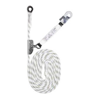
B. COMPONENTS. 1. Steel travelling grip device; 2. Energy absorber made of polyester; 3. Feature of the
device; 4. Connector of the energy absorber; 5. The upper end of a work line fitted with a thimble; 6. Working line
feature; 7. 12 mm diameter polyester core working line; 8. Lower end of the working line in the form of a safety
loop; 9. Maximum permissible length of shock absorber with the connector = 32 cm.
C. FIXING THE WORKING LINE TO A STRUCTURAL ANCHOR POINT The anchor line (working line) must be
fixed to a structural anchor point using a connector or anchoring device complying with EN 362 (C.1 and C.2) or
EN 795 (C.3). The static strength of the structural anchor point must be at least 12 kN. The shape and design of
the structural anchor point must protect against the spontaneous disengagement of the device (C.4, C.5, C.6).
The use of certified and approved anchor points complying with EN 795 is recommended.
D. CONNECTING THE TRAVELLING GRIP DEVICE TO THE FULL BODY HARNESS. The connector of the
device must be connected to the attachment point of the full body harness, marked with a capital "A". The use of
a front attachment point is recommended. The full body harness must comply with EN361.
E. KEY PRINCIPLES WHEN WORKING WITH THE LINOSTOP DEVICE II ED. E.1 Ensure safe fall arrester
action by providing a minimum required free space 'H' of at least 2.17 m below the user. When working with an
anchor line in excess of 20 m, the free space below the user must be increased by 5% of the device length. If the
anchor line is fixed to an anchor point located directly above the position of the user, the maximum permissible
bending angle of this anchor line with respect to the vertical is 15° relative to the line of the structural anchor point
during the user's sideways movement. E.2 The device has been tested in accordance with the requirements of
PPE-R/11.075. The scope of application covers works involving the user moving horizontally on sites that
present a risk of falling over the edge (e.g. on flat roofs). The minimum edge radius must be 0.5 mm. If the edge is
sharp or poses a high risk of damage to the line, e.g. there are burrs on its surface, install suitable edge
protection. The minimum free space ensuring safe fall arrest, calculated from the edge through which a fall may
occur, must be 3.29 m. E.3 The anchor line (working line) is not located below user's feet's level. E.4 Ensure the
EN353-2:2002
0082
+ PPE-R/11.075
9
3
4
ł
C
C.1
C.4
E.3
E.5
Krawędź
Krawędź
max. 1,5 m
max. 1,5 m
bending angle of the anchor line on the edge when the line is to stop a fall is at least 90°. E.5 When working with
the guided type fall arrester, ensure you handle the anchor line so that it is not too loose. The user can adjust the
length of the fall arrester (by sliding the travelling grip device over the anchor line) only when the user is not
moving towards the edge that he/she can fall over. To avoid the risk of the 'pendulum effect' during a fall, ensure
that you move no farther than 1.5 m horizontally with respect to the vertical axis of the anchor point, in either
direction. If this is not the case, an anchoring device complying with EN795 Type C or Type D should be used
instead of a structural anchor point. When a horizontal anchor line complying with EN 795 Type C is used, its
possible deflection should be taken into account, which will affect the amount of free space "H" below the
workstation. Read and consider all information contained in the instructions manuals of horizontal anchor lines.
When the equipment is stopping a fall over the edge, the user can sustain injuries from impact against parts of
the building or other structures. Ensure you prepare and practise special rescue procedures in case of such
occurrences. NOTE: When climbing and lowering in the first 2 metres above ground level, the user may not be
properly protected from collision with the ground during a fall, so extreme caution is required when working at
such heights.
F. DESCRIPTION OF MARKINGS. a) type of device; b) model; c) number and year of issue of the European
standards applicable to the device; d) CE marking and number of the notified body supervising the
manufacturing process; e) read the instructions for use carefully before use; f) length of the anchor line (work
line); g) approved for horizontal use/to prevent falling over the edge as required by PPE-R/11.075; h) anchor line
(work line) shall not be stressed on sharp edges; i) maximum rated load; j) diameter and part number of the
anchor line (work line) to be used with the LINOSTOPII ED guided type fall arrester; k) month and year of
manufacture; l) serial number of the guided type fall arrester; m) manufacturer's designation
G. SCHEDULED INSPECTION The equipment is subject to scheduled maintenance inspections every 12
months from the date of first use. The scheduled inspections must be carried out by a qualified professional only,
with knowledge and skills required to carry out scheduled inspections of PPE. Depending on the type of work
and working site environment, the equipment may need maintenance work more frequently than every 12
months. After 5 years of use, we recommend a periodic inspection by a company or person authorised by the
device manufacturer. Ensure you record each scheduled inspection in the equipment's operation sheet.
H. MAXIMUM SERVICE LIFE OF THE EQUIPMENT The maximum service life of the appliance is 10 years from
the date of manufacture.
H. WITHDRAWAL FROM USE The equipment must be taken out of service and subsequently disposed of
immediately after it arrested a fall or it is found to be unfit for further use on the basis of an inspection or if any
doubts as to its good working condition arise.
NOTE: The maximum service life of the equipment depends on the intensity of use and environmental
conditions. Using the equipment in harsh conditions, marine environment, on sharp edges, when exposed to
high temperatures or aggressive substances, etc., can mean that the equipment must be withdrawn from use
even after one use.
I. ESSENTIAL RULES FOR THE USERS OF PERSONAL PROTECTIVE EQUIPMENT AGAINST FALLS
FROM A HEIGHT
EN Guided type fall arrester with anchor line
D
C.2
C.3
C.5
C.6
E.4
F
a
Guided type fall arrester
b
LINOSTOPII ED
EN 353-2:2002
c
d
e
Length: xx m
f
g
PPE-R/11.075
h
i
max
max. 1,5 m
max. 1,5 m
120 kg
j
Date of manufacture:
k
l
m
LINOSTOPII ED
Ref. AC061ED
A
0082
Ø12 mm
Ref. AC061ED
Serial number:
MM.YYYY
XXXXXXXXXXX
Advertisement

Related Manuals for Protekt LINOSTOPII ED


Summary of Contents for Protekt LINOSTOPII ED
- Page 1 When a horizontal anchor line complying with EN 795 Type C is used, its uses a polyester anchor line (working line) with a diameter of 12 mm. The LINOSTOPII ED device is a ready-to- possible deflection should be taken into account, which will affect the amount of free space "H"...
- Page 2 It is prohibited to combine the equipment components where the safe operation of one component affects Manufacturer: PROTEKT – Starorudzka 9 – 93-403 Łódź – Poland or interferes with the safe operation of another. Before each use of PPE, it is mandatory to carry out an initial check of the equipment for proper operation to This device meets the requirements of Regulation (EU) 2016/425 on personal protective equipment.
Need help?
Do you have a question about the LINOSTOPII ED and is the answer not in the manual?
Questions and answers