Advertisement
Quick Links
If you have any questions regarding assembly or if parts are missing, DO NOT return this item to the
store where it was purchased. Please call our toll-free customer service number and have your
instructions and parts list ready to provide the model name, part name or factory number:
Pacific Standard Time: 8:30 a.m. - 4:30 p.m., Monday - Friday
Or visit our website 24 hours a day, 7 days a week for product assistance at
THIS INSTRUCTION BOOKLET CONTAINS IMPORTANT SAFETY INFORMATION.
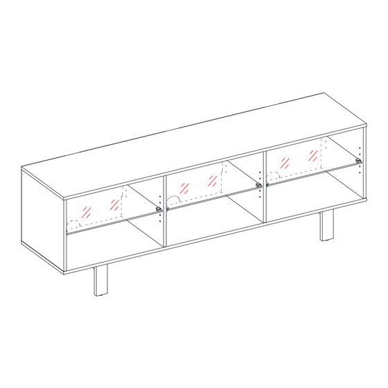
Illumina 65" TV Stand
Model # ARAVCM65-6BK
ADULT ASSEMBLY REQUIRED
1-866-942-5362
www.whalenfurniture.com
Or e-mail your request to: parts@whalenfurniture.com
PLEASE READ AND KEEP FOR FUTURE REFERENCE.
Date 2024-08-19
LOT NUMBER:
DATE PURCHASED: /
Rev. 0001-A
/
Advertisement

Related Manuals for Whalen Illumina ARAVCM65-6BK


Summary of Contents for Whalen Illumina ARAVCM65-6BK
- Page 1 LOT NUMBER: DATE PURCHASED: / Illumina 65” TV Stand Model # ARAVCM65-6BK ADULT ASSEMBLY REQUIRED If you have any questions regarding assembly or if parts are missing, DO NOT return this item to the store where it was purchased. Please call our toll-free customer service number and have your instructions and parts list ready to provide the model name, part name or factory number: 1-866-942-5362 Pacific Standard Time: 8:30 a.m.
- Page 2 IMPORTANT Before you begin: Open, identify and count all parts prior to assembly. Lay out parts on a flat and non-abrasive surface. You will need the parts identified on page 4 and 5 of this instruction manual. NOTE: IT IS VERY IMPORTANT TO USE GLUE WITH THE DOWELS. EXCESS GLUE CAN BE WIPED OFF WITH A DAMP CLOTH.
-
Page 3: Important Safety Instructions
Carefully Read all Instructions Installing and Operating Fixture IF YOU HAVE ANY QUESTIONS REGARDING THE PROPER INSTALLATION CONSULT A QUALIFIED ELECTRICIAN TO REDUCE THE RISK OF FIRE, ELECTRICAL SHOCK OR INJURY TO PERSONS, PLEASE FOLLOW THE NEXT: Use only insulated staples or plastic ties to secure the cords. ... - Page 4 Parts and Hardware List Please read completely through the instructions and verify that all listed parts and hardware are present before beginning assembly. A- Top Panel (Qty. 1) B- Bottom Panel (Qty. 1) C- Left Side Panel (Qty. 1) D- Partition Panel (Qty. 2) E- Right Side Panel (Qty.
- Page 5 Parts and Hardware List Please read completely through the instructions and verify that all listed parts and hardware are present before beginning assembly. (1) 1/4” x 15mm Bolt (2) Lock Washer (3) Flat Washer (Qty. 4+1 extra) (Qty. 4+1 extra) (Qty.
- Page 6 Assembly Instructions NOTE: Please do not fully tighten all bolts until you finish assembling all parts. Once assembled, go back and fully tighten all bolts. This will make the assembly easier. 1. Unpack the unit and confirm that you have all the hardware and required parts. Assemble the unit on a carpeted floor or the empty carton to avoid any scratch.
- Page 7 Assembly Instructions 4. Glue the Wood Dowels (6) into the inner holes on both Side Panels (C and E) and Partition Panels (D) as shown. NOTE: It is very important to use a small amount of glue on both ends of dowels and wipe away the excess glue immediately.
- Page 8 Assembly Instructions The cam screw holes face inward. 6. Attach the Side Panels (C and E) to the Top Panel (A) by engaging four Cam Locks (4). 7. Orient and place the Bottom Panel (B) onto the vertical panels (C, D and E) properly and fasten it into place with eight 50mm Screws (8).
- Page 9 Assembly Instructions H/ I 8. Attach the assembled base to the Bottom Panel (B) with ten 50mm Screws (8). 9. Route the cables of Rocker Switch (K) through the round hole on the Right Side Panel (E) and snugly fit into place.
- Page 10 Assembly Instructions 10. Firmly fit and center the LED lighting (J) containment barrier onto each Glass Shelf (G). male male connector connector C/D/E 11. Ask for assistance to turn the assembled unit on its front edges. 12. Insert the Shelf Supports (9) into the holes at the desired height inside each compartment. Make sure you place four clips at the same level.
- Page 11 Assembly Instructions The two side round holes run against the right side panel (E). 14. Now, go back and securely tighten all the Cam Locks and Screws. Make sure all the parts are tight and there are no gaps between the parts. This will help keep the unit square. 15.
- Page 12 Assembly Instructions 17. Combine the LED lighting set 2-pin male connectors with the female connectors as shown and plug the AC to DC Adapter (L) to the power transformer. 18. Ask for assistance to lift the assembly unit upright and position it near the final location. 19.
- Page 13 Assembly Instructions Wall Wooden stud Metal bracket Wall Long screw Short screw Connector Floor leveler Steel cable Tools required: Phillips screwdriver, stud finder, tape measure, pencil, power drill and 1/8” drill bit. 20. Ask for assistance to position the assembled unit at the desired location against a wall. If necessary, adjust the pre-attached Floor Levelers at the bottom of the base frame to level the unit.
- Page 14 Care and Maintenance Use a soft, clean cloth that will not scratch the surface when dusting. Use of furniture polishes is not necessary. Should you choose to use polishes, test first in an inconspicuous area. Using solvents of any kind on your furniture may damage the finish. ...
-
Page 15: Quality Guarantee
Should this product be defective in workmanship or materials or fail under normal use, we will repair or replace it for up to one (1) year from date of purchase. Every Whalen Furniture product is designed to meet your highest expectations. We guarantee that you will immediately see the value of our fine furniture.
Need help?
Do you have a question about the Illumina ARAVCM65-6BK and is the answer not in the manual?
Questions and answers