
Related Manuals for Linde 388-01 Series


Summary of Contents for Linde 388-01 Series
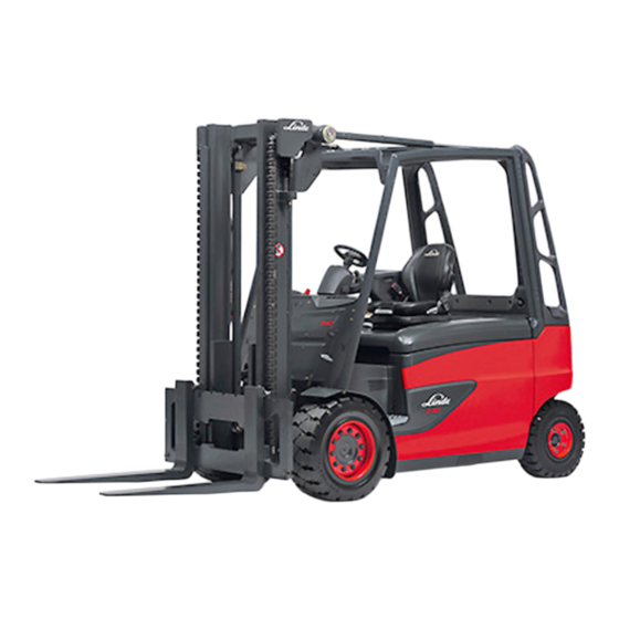
- Page 1 Electric forklift trucks Original instructions Series 388-01 E35 / 40 / 45 / 50 3888011701 EN – 12/2017...
- Page 3 Preface Linde − Your Partner With over 100,000 fork lift trucks and ware- Your local Linde partner can offer you a house machines sold annually, Linde is one of complete package from a single source; the world's leading manufacturers of material ranging from expert advice on all aspects handling equipment.
- Page 4 Internet address and QR code By entering the address www.linde-mh.com/VDMA in a web browser or by scanning the QR code, information can be accessed at any time. Operating Instructions – 3888011701 EN – 12/2017...
-
Page 5: Table Of Contents
Table of contents Introduction Your industrial truck ........... 2 Intended use . - Page 6 Table of contents Truck numbers and identification plates ........35 Truck configuration .
- Page 7 Linde Safety Pilot (LSP) assistance system ....... . . 147...
- Page 8 Table of contents Transporting the truck using a lorry or flat-bed trailer ......202 Crane loading ............204 Service work Safety information regarding servicing work .
- Page 9 Table of contents Hydraulic system: Checking for leak tightness ....... 248 Cleaning the radiator .
-
Page 11: Introduction
Introduction... -
Page 12: Your Industrial Truck
Introduction Your industrial truck Your industrial truck offers optimum economic efficiency, safety Industrial truck model: and driving comfort. It is primarily down to Production number / you to maintain these characteristics for a year of manufacture: long time and take advantage of the resulting Handover date: benefits. -
Page 13: Intended Use
Introduction Intended use Intended use Driving routes The industrial truck may only be used as permitted. Driving routes shall be sufficiently paved, The industrial truck is used for moving and level and free of objects. Drain channels and lifting the loads indicated on the capacity rating railways crossings, etc., shall be levelled and, plate. -
Page 14: Impermissible Use
Introduction Impermissible use Attachments The permissible carrying capacity of the attachments and the permitted load of the Attachments shall only be used as permitted. industrial truck (carrying capacity and load The driver shall be instructed in the handling moment) combined with the attachments shall of attachments. -
Page 15: Description Of Use And Climatic Conditions
Introduction Description of use and climatic conditions Description of use and climatic conditions Normal use Special use (partly with special mea- sures) • Indoor and outdoor use • Ambient temperature in tropical regions to • Ambient temperature in tropical and Nordic 40 °C regions ranging from -10 °C to 40 °C •... -
Page 16: Technical Description
Introduction Technical description Technical description The electric trucks from series 388 enable Thanks to the twin pedal system, forwards and loading and palletising for loads of up to reverse travel is controlled steplessly via the 3.5 tonnes with the E 35, up to 4 tonnes with digital controller. -
Page 17: Electrical System
Electrical system • The electric regenerative brake, or LBC The well-protected electrical system is posi- (Linde Brake Control) for energy recovery, tioned at the front, under the right-hand truck which is automatically actuated when the console. accelerator pedal is released or when the drive direction is changed. -
Page 18: Receiving The Industrial Truck
Introduction Receiving the industrial truck Receiving the industrial truck Before the industrial truck leaves our factory, CAUTION it undergoes a thorough inspection process in Risk of overload on battery female connector. order to guarantee that it is in perfect condition For trucks that are supplied from the factory without and that it contains all of the equipment batteries, a battery female connector is also requi-... -
Page 19: Legal Requirements For Marketing
Introduction Legal requirements for marketing Legal requirements for marketing Declaration Linde Material Handling GmbH Carl-von-Linde-Platz D-63743 Aschaffenburg, Germany We declare that the machine according to these operating instructions Industrial truck according to these operating instructions Model complies with the most recent version of machinery directive 2006/42/EC. -
Page 20: Disposing Of Components And Batteries
Introduction Disposing of components and batteries Disposing of components and batteries The truck is composed of different materials. If NOTE components or batteries need to be replaced The documentation provided by the battery and disposed of, the national regulations must manufacturer must be observed when dispo- be observed with regard to: sing of batteries. -
Page 21: Safety
Safety... -
Page 22: Safety Guidelines
Safety Safety guidelines Safety guidelines The operating company or the person it has commissioned must ensure that the driver understands all safety information and that all guidelines and safety regulations are observed. During training, drivers must familiarise themselves with the following: •... - Page 23 Safety Safety guidelines DANGER Any additional bores or welding on the overhead guard will compromise its rigidity. It is therefore strictly prohibited to drill holes in the overhead guard or to perform welding work on it. CAUTION Risk of overloading the battery female connector. This means that only the embedded battery female connector (MRC socket) that has been approved by the manufacturer may be used.
- Page 24 Safety Safety guidelines WARNING Depending on the duration of use and the operating time, components carrying exhaust air may become hot. Protective equipment must therefore be worn. WARNING The truck working area must be sufficiently lit. If it is not sufficiently lit, working spotlights must be installed to ensure that the driver can see properly.
-
Page 25: Safety Guidelines For The Load-Dependant Assistance System
Safety Residual risks Safety guidelines for the load-dependant assistance system (load weight indicator "plus") Hazard assessment The load-dependant assistance system reduces the risk of tipping and increases the The load-dependant assistance system stability of the truck. changes the driving characteristics and op- •... -
Page 26: Stability
Safety Stability Even beyond the narrow danger areas of the • Escape of consumables due to leakages or industrial truck itself, a residual risk cannot the rupture of lines, hoses or containers, be excluded. Persons in the area around the •... -
Page 27: Handling Consumables
Safety Handling consumables Handling consumables • Comply with the statutory provisions. ENVIRONMENT NOTE • Before performing greasing, filter changes Consumables must be handled properly or any work on the hydraulic system, and in accordance with the manufacturer's carefully clean the area around the part instructions. -
Page 28: Fit Attachments
Safety Fit attachments be carried out by competent personnel, in or- der to ensure proper condition. There is a recommendation setting out the scope of the periodic safety inspection —FEM 4.004 of the European Industrial Truck Asso- ciation— which defines a test log to document the current safety inspection and an inspection sticker for the next safety inspection. -
Page 29: Hydraulic Connection
Safety Fit attachments Load Load Class capacity centre Design As per Truck of gravity ISO 2328 400 and 0 - 999 1000 - 500 and 2500 2501 - 500 and 21.5 4999 5000 - 25.5 8000 8001 - 10999 Integrated attachments are made to match the installed lift mast. - Page 30 Safety Fit attachments When the pressure is reduced, hydraulic oil escapes. Disconnect hydraulic lines. Connect hydraulic lines to attachment. With depressurisation: (special equipment) Depressurise the hydraulic lines as de- scribed in section "Depressurisation". Disconnect hydraulic lines. ...
-
Page 31: Emergency Exit With Attached Rear Window
Safety Emergency exit with attached rear window Emergency exit with attached rear window NOTE Industrial trucks with a built-in front window and rear window: If an industrial truck breaks down in a narrow aisle, it may no longer be possible to exit the truck at the side. -
Page 32: Emergency Lowering
Safety Emergency lowering Emergency lowering If there is a malfunction, the fork carriage can be lowered manually. The control valve (3), which is located under the bottom plate for the pedals on the right- hand side of the truck, is equipped with an emergency lowering screw (1). -
Page 33: Emergency Lowering For Trucks With An Elevated Driver's Compartment
Safety Emergency lowering for trucks with an elevated driver's compartment After lowering, turn the emergency lowering screw (1) in a clockwise direction (tightening torque 10 Nm). Otherwise it will not be possible to operate the fork carriage lift function using the joystick ... - Page 34 Safety Emergency lowering for trucks with an elevated driver's compartment Turn the knurled nut (4) under the support bracket (3) downwards by about 20 mm. Remove the bottom plate. DANGER Risk of accident when lowering the fork carriage. People must not stand near the fork arms when they are being lowered.
-
Page 35: Towing
Safety Towing Towing If the truck ever has to be towed in an emer- gency, the multi-disc brake on the drive axle can be released for this purpose. WARNING Risk of accident and risk of fatal injury! When the multi-disc brake is released, the truck can no longer be braked. - Page 36 Safety Towing Releasing the multi-disc brake The brake valve (1) is located under the bottom plate. Remove the bottom plate. Tighten the screw (2) clockwise to the stop. e3871500 Remove the lever (see arrow) from the bottom plate. e3871444 Operating Instructions –...
-
Page 37: After Towing
Safety Towing Insert the lever (5) into the opening (4) provided in the front wall and place the lever on the tappet (3). Move the lever downwards approx. 20 times (pump the lever). This results in a build-up of pressure and releases the multi-disc brake. - Page 38 Safety Towing Restoring braking readiness Once the towing procedure has been per- formed, braking readiness must be restored. Unscrew the screw (2) again, rotating it in an anti-clockwise direction to the stop. Pull out the lever (5) from the opening (4) again and place the lever back in the bottom plate.
-
Page 39: Overview
Overview... -
Page 40: Truck Overview
Overview Truck overview Truck overview e3871101 Lift mast Counterweight Tilt cylinder Step Overhead guard Pedal group/reverse accelerator pedal Load capacity diagram Left wheel gear (on the inside of the overhead guard) Fork carriage Display unit Sideshift Rear-view mirror Fork arms Switch panel Lift mast chain Toggle switch for special equipment... -
Page 41: Operating Devices
Overview Operating devices Operating devices e3871502 Steering wheel Joystick for working hydraulics Steering column adjusting knob Armrest Turn indicator switch Horn signal button Parking brake switch Forward travel accelerator pedal Key switch Stop pedal Emergency off switch Lever for adjusting the driver's seat Control panel for the heating system (special Reverse travel accelerator pedal equipment) -
Page 42: Switch Panel
Overview Switch panel Switch panel e3861458a Clipboard light and interior lighting Roof panel wiper - intermittent mode or Standard lighting or higher lighting continuous operation on/off (the washer Working spotlight, position 1/2 system is always activated) Working spotlight, position 3/4 or working Hazard warning light spotlight, position 5/6 Rotating beacon, flashing beacon or... -
Page 43: Labelling
Overview Labelling Labelling nameplate Type-Modele-Typ /Serial no.-No. de serie-Serien-Nr. / year-annes-Baujahr Rated capacity Unladen mass Capaciti nominale Masse a vide Nenn-Tragfähigkeit Leergewicht max. Battery voltage Tension batterie Batteriespannung min. Rated drive power Paissance metr. nom. Nenn-Antriebsleistung see Operatig instructions voir Mode d' emplol siehe Betriebsanleitung 000 938 54 07 Type-Modele-Typ... - Page 44 Overview Labelling NOTE The CE mark confirms compliance with the EC machinery directive and with all regulations applicable to the truck. e3871100 Nameplate Manufacturer Model / Production no. / Year of manufac- ture Tare weight Max. battery weight / min. battery weight Ballast weight Placeholder for data matrix code CE mark...
-
Page 45: Truck Numbers And Identification Plates
Overview Labelling Truck numbers and identification plates Serial number (stamped) Lift mast number (adhesive label) Identification plate for the drive axle e3871637 Serial number stamp location The stamp location for the serial number is being moved from the right-hand mudguard to the footwell. - Page 46 Overview Labelling Additional lift mast number Additional label for the lift mast number (from 05/2017) e3871638 "Truck configuration" label "Truck configuration" label (for a description, see "Truck configuration label") e3871639 Operating Instructions – 3888011701 EN – 12/2017...
- Page 47 Overview Labelling Identification plate for the steering axle Identification plate for the steering axle e12790085 Operating Instructions – 3888011701 EN – 12/2017...
-
Page 48: Truck Configuration
Overview Labelling Truck configuration "Truck configuration" sign NOTE If attachments and conversions are required, please contact your service partner. A new "truck configuration" label must then be created and attached to the truck by the service partner. Chassis serial number Identification plate designation for lift mast with: Lift mast series –... - Page 49 Overview Labelling Operating Instructions – 3888011701 EN – 12/2017...
-
Page 50: Display Unit
Overview Display unit Display unit 10:30 03.03.2015 4 20 Display_e0001d Operating Instructions – 3888011701 EN – 12/2017... - Page 51 Overview Display unit Display unit Control buttons Indicator light for direction indicator sys- "Confirm" button tem/hazard warning system (green) "Down" button Motor temperature at upper limit (red) "Up" button Neutral warning light (red) "Back" button Error in electrical controllers or integrated battery charger (red) Display Forwards drive direction (single-pedal...
-
Page 52: Display Unit: Symbols On The Display
Overview Display unit: Symbols on the display Display unit: Symbols on the display Display_e0002 Symbol Function Status display menu Displays the status Favourites display menu Displays favourites Displays settings Settings menu Malfunctions menu Displays malfunctions Time/date Time and date display. Steering angle Bar display of current steering angle (central position ≙... - Page 53 Overview Display unit: Symbols on the display Symbol Function 17 Units Displays units. Setting: metric (ISO) units (kg | km/h | m) or imperial units (lbs | mph | ft). 18 Date format Date format and 12/24-hour format selection. Setting: mm/dd/yyyy/12-hr or dd/mm/yyyy/24-hr Clock display: am = morning/pm = afternoon.
-
Page 54: Display Unit: Menu Structure On The Display
Overview Display unit: Menu structure on the display Display unit: Menu structure on the display Status display menu 10:30 10:30 03.03.2015 03.03.2015 4 20 4 20 km/h 1.10 Display_e0003c Operating Instructions – 3888011701 EN – 12/2017... - Page 55 Overview Display unit: Menu structure on the display Status display menu Time/date (factory setting) Steering angle Driving speed Steering angle/driving speed Operating hours Remaining travel time (factory setting) Consumption/average consumption Drive unit temperature Pump motor temperature Tilt angle/load weight (special equipment) 1.10 Favourites display menu Settings menu...
- Page 56 Overview Display unit: Menu structure on the display Favourites display menu 10:30 03.03.2015 4 20 km/h km/h Display_e0004c Operating Instructions – 3888011701 EN – 12/2017...
- Page 57 Overview Display unit: Menu structure on the display Status display menu Favourites display menu Steering angle/time/operating hours Steering angle/time/driving speed Driving speed/steering angle Steering angle/tilt angle (factory setting)/load weight (special equipment) Tilt angle (factory setting)/load weight (special equipment) Settings menu Malfunctions menu NOTE The Favourites display saves the last dis-...
-
Page 58: Settings Menu
Overview Display unit: Menu structure on the display Settings menu 10:30 03.03.2015 4 20 km/h 3.10 3.11 3.12 Display_e0005c Operating Instructions – 3888011701 EN – 12/2017... - Page 59 Overview Display unit: Menu structure on the display Status display menu Favourites display menu Settings menu Language Units Date format and "12/24-hour format" Date Time Brightness Resetting consumption Restoring factory settings System information 3.10 Drive mode Speed limit 3.11 3.12 Mast vertical Malfunctions menu Operating Instructions –...
- Page 60 Overview Display unit: Menu structure on the display Malfunctions menu 10:30 03.03.2015 4 20 km/h Display_e0006c Operating Instructions – 3888011701 EN – 12/2017...
- Page 61 Overview Display unit: Menu structure on the display Status display menu Favourites display menu Settings menu Malfunctions menu Error codes Error lights QR code NOTE The "malfunctions" symbol (5) is displayed in the following colours depending on the status of the truck: "Yellow"...
- Page 62 Overview Display unit: Menu structure on the display Operating Instructions – 3888011701 EN – 12/2017...
-
Page 63: Operation
Operation... -
Page 64: Service Plan Before Initial Commissioning
Operation Service plan before initial commissioning Service plan before initial commissioning Gearboxes Check the oil level in the planetary transmission and check for leaks. Chassis frame Check the wheel fastenings and tighten. Check the tyre pressure. Check the brake system. Check the steering system. -
Page 65: Pre-Shift Checks
Operation Pre-shift checks Pre-shift checks Chassis, bodywork and fittings Check that the adjusting mechanism on the steering column is secure. Driver's seat and seat belt: check condition (visual inspection). Check the container in the washer system. Roof panel (special equipment): check condition (visual inspection). Chassis frame Check the tyres and rims (tread, external damage, air pressure). -
Page 66: Driver's Compartment
Operation Driver's compartment Driver's compartment Entering and exiting the truck WARNING Entering and exiting the truck can result in injuries to the feet or back. Always face the truck when climbing in and out. NOTE Do not use the steering wheel or the joysticks as an aid to get in or out of the cab. -
Page 67: Minimum Distance Between Head And Overhead Guard
Operation Driver's compartment Minimum distance between head and overhead guard Certain versions (e.g. those with a rotary seat or container roof) have a reduced clearance between the seat and overhead guard. WARNING Risk of head injuries. The truck may only be used by persons whose normal operating posture is such that there is a minimum distance of 30 mm between their head and the overhead guard. -
Page 68: Adjusting The Seat Backrest
Operation Driver's compartment Longitudinal adjustment WARNING There is a risk of crushing if the lever is grasped fully. Only grasp the lever by the trough provided for this purpose. Pull the lever (1) upwards. Choose the most comfortable position in rela- tion to the steering wheel and the accelerator pedals. - Page 69 Operation Driver's compartment Adjusting the lumbar support (only on a comfort driver's seat) NOTE The lumbar support enables the seat backrest contour to be optimally adapted to the driver's body. Turn the knob (5) to the left or right. The extent to which the lower and upper areas of the backrest are curved is adjusted individually.
-
Page 70: Adjusting The Driver's Seat With Rotating Device
Operation Driver's compartment Adjusting the driver's seat with rotating device CAUTION The driver's seat must not swivel while the industrial truck is in use. It should therefore be ensured that the rotating device is locked. The driver's seat with rotating device offers better rear visibility during reverse travel over long distances. -
Page 71: Comfort Driver's Seat With Air Suspension
Operation Driver's compartment Comfort driver's seat with air suspension WARNING If the seat is not adjusted correctly, this may cause injury to the driver's back. The setting devices for the driver's seat must not be used during operation of the truck. Before commissioning the truck each time and whenever changing drivers, adjust the seat to correspond to the driver's weight and make sure... - Page 72 Operation Driver's compartment Setting the driver's weight NOTE The individual driver's weight must be set when the driver's seat is under load. Check the weight adjustment in the inspec- tion window (4). The correct driver's weight has been selected when the arrow is in the middle of the inspec- tion window (4).
- Page 73 Operation Driver's compartment Adjusting the lumbar support NOTE The lumbar support enables the seat backrest contour to be optimally adapted to the driver's body. Turn the knob (5) to the left or right. The extent to which the lower and upper areas of the backrest are curved is adjusted individually.
-
Page 74: Luxury Driver's Seat With Manual Weight Setting
Operation Driver's compartment Luxury driver's seat with manual weight setting WARNING If the seat is not adjusted correctly, this may cause injury to the driver's back. The setting devices for the driver's seat must not be used during operation of the truck. Before commissioning the truck each time and whenever changing drivers, adjust the seat to correspond to the driver's weight and make sure... - Page 75 Operation Driver's compartment Setting the driver's weight NOTE The individual driver's weight must be set when the driver's seat is under load. Check the weight adjustment in the inspec- tion window (4). The correct driver's weight has been selected when the arrow is in the middle of the inspec- tion window (4).
- Page 76 Operation Driver's compartment Adjusting the seat angle Pull the lever (5) upwards. The seat base is moved to the desired position by applying pressure to the seat base or removing pressure from it. Adjusting the seat depth Pull the lever (6) upwards. Move the seat base to the desired position by simultaneously sliding the seat base forwards or backwards.
-
Page 77: Luxury Driver's Seat With Automatic Weight Setting
Operation Driver's compartment Luxury active driver's seat with manual weight setting The luxury active driver's seat is operated in the same way as the luxury driver's seat. The only difference is the way in which the seat heater is activated. Activating the seat heater (luxury active driver's seat) ... - Page 78 Operation Driver's compartment Longitudinal adjustment Pull the lever (1) upwards. Choose the most comfortable position in rela- tion to the steering wheel and the accelerator pedals. Move the driver's seat forwards or back- wards in the rails. Allow the lever (1) to snap into place. Adjusting the seat backrest ...
- Page 79 Operation Driver's compartment Adjusting the lumbar support NOTE The lumbar support enables the seat backrest contour to be optimally adapted to the driver's body. Press button (6). The extent to which the upper area of the backrest is curved is adjusted individually. ...
-
Page 80: Adjusting The Driver's Seat Armrest
Operation Driver's compartment Push the switch (9) to the centre position to deactivate the seat air conditioning. NOTE The maximum temperature is predefined. Adjusting the driver's seat armrest Sit on the driver's seat and release clamping screw (1). ... -
Page 81: Adjusting The Steering Column
Operation Driver's compartment Adjusting the steering column DANGER It is not possible to drive safely when the clamping screw is open. Only adjust the steering column when the truck is stationary. Before attempting to drive the truck, ensure that the steering column is locked. -
Page 82: Seat Belt
Operation Driver's compartment Seat belt Fastening the seat belt DANGER There is a risk to life if the driver leaves the vehicle in an uncontrolled manner. For this reason, the seat belt must always be worn when operating the truck! The seat belt should only be worn by one person. -
Page 83: Unfastening The Seat Belt
Operation Driver's compartment Pull the seat belt (3) smoothly out of the belt retractor (1) to the left. Position belt over the lap, not over the stomach. Allow the latch plate (2) to snap into place in the buckle (4). -
Page 84: Horn
Operation Driver's compartment Horn The horn is used as a warning signal, e.g. at blind spots and junctions. The horn knob is easily accessible in the armrest area. Push in the horn knob on the armrest (see arrow) to sound the horn. e3871151 Operating Instructions –... -
Page 85: Lighting
Operation Driver's compartment Lighting NOTE The arrangement of the individual switches on the overhead console may vary depending on the version. Observe the switch symbols. Switching on the clipboard light Move the toggle switch (1) to the centre position (setting 1). Switching on the interior lighting ... - Page 86 Operation Driver's compartment The upper front working spotlights are switched on. Switching on the rear working spotlights Press the toggle switch (5) to the end position (setting 2). The rear working spotlights are switched on. Switching on the working spotlights for reverse travel ...
- Page 87 Operation Driver's compartment Switching on the rotating beacon/flash- ing beacon Depending on the equipment there are three different versions. Version 1: Press the toggle switch (7). Set the toggle switch (7): • Setting 0: light "OFF" • Setting 1: light "ON" for reverse travel •...
- Page 88 Operation Driver's compartment Switch the flasher unit (1) on the steering wheel downwards. The direction indicators on the truck flash on the left. The left-hand indicator light on the display unit (see arrow) flashes. Rear lights NOTE The two rear light clusters contain the stop light, the rear light and the direction indicator.
-
Page 89: Bluespot Tm
Operation Driver's compartment BlueSpot The BlueSpot comprises a visual warning unit that enables the early detection of indust- rial trucks in driving areas with low visibility (such as drive lanes and high racks), as well as at blind junctions. e3871479 The BlueSpot is mounted on a support on top of the overhead guard and projects a high-... - Page 90 Operation Driver's compartment Switching on the BlueSpot Depending on the equipment fitted, there are three different ways to activate the BlueSpot. Variant 1: Press the toggle switch (7). Switch settings for the toggle switch: • Level 0: BlueSpot "OFF" •...
-
Page 91: Windscreen Wipers
Operation Driver's compartment Windscreen wipers NOTE Depending on what has been preselected using the toggle switches (7, 8), the various wiper functions can be switched on and off using the central multifunction lever (6). The wiper functions differ for forwards and reverse travel. - Page 92 Operation Driver's compartment Turning on the rear windscreen wiper Truck in reverse travel: Switch toggle switches (7) and (8) to the zero position. Pull the multifunction lever (6) on the steering wheel upwards (3) from the centre position. The rear window wiper remains in intermittent mode as long as the lever is actuated.
- Page 93 Operation Driver's compartment Press the multifunction lever (6) on the steering wheel downwards (4) from the centre position. The front windscreen wiper is in intermittent mode and the rear window wiper is in continu- ous mode. Truck at a standstill or in forwards or reverse travel: ...
- Page 94 Operation Driver's compartment Pull the multifunction lever (6) on the steering wheel upwards (3) from the centre position. As long as the lever is actuated, the front windscreen wiper remains in intermittent mode and the roof panel wiper remains in continuous mode.
-
Page 95: Window Heater
Operation Driver's compartment Window heater Switching on the rear window heating Press push button (1). Dummy (2) test. Dummy (1) test. The rear window heating is switched off. Dummy (1) test. The rear window heating is in operation for a further 15 minutes. -
Page 96: Heating System
Operation Driver's compartment Heating system Heating system operating devices e3871134a Rotary switch for adjusting the temperature Rotary switch for adjusting the flap positions Rotary switch for adjusting the blower for windscreen defrosting/footwell ventila- positions tion Cab air nozzles Switching on the heating system ... -
Page 97: Radio
Operation Driver's compartment Radio NOTE You will find the description for the radio in the attached manufacturer's operating instructions. Buckle monitoring on seat belt DANGER There is a risk of fatal injury if the truck is vacated in an uncontrolled manner. The seat belt must always be fastened when operating the truck! The seat belt must only be worn by one person. - Page 98 Operation Driver's compartment in use, but also the actuation sequence of the seat switch and belt buckle. Sit on the driver's seat. The seat switch is actuated. Pull the seat belt (2) smoothly out of the retractor to the left. ...
-
Page 99: Overhead Guard With Optimised Visibility
Operation Driver's compartment Settings The following settings can be configured by your service partner: • Truck response: movement prevented or travel at creep speed • Switch off buckle monitoring Contact your service partner. Overhead guard with optimised visibility On overhead guards with optimised visibility, bracing struts as protection for a falling load are not fitted across the viewing range in the roof panel. -
Page 100: Display Unit
Operation Display unit Display unit Starting up the system Switching on the display unit After the electrical system is switched on, the display unit (1) performs the following actions: • Self-testing of the lights: All displays (2) light up for approx. 2 seconds. •... -
Page 101: "Service Interval" Indicator
Operation Display unit "Service interval" indicator When a service is imminent, the symbol (8) flashes for about 10 seconds after the electrical system is switched on. After this time the symbol (8) lights up. "Service interval exceeded" message If the "Service required" message (9) is displayed, the preset service interval has been exceeded. -
Page 102: Control Buttons
Operation Display unit Control buttons The display unit has four control buttons. Back button (1) Briefly press the "Back" button to perform the following action: • Move back one level. Press and hold down the "Back button" to perform the following action: •... -
Page 103: Status Display Menu
Operation Display unit Status display menu NOTE The status display menu can be individually configured. Press the button. Use the buttons to select the 1600 desired display area (1) or (2). 10,2 ° Press the button to confirm. ... -
Page 104: Favourites Display Menu
Operation Display unit Favourites display menu Press the button. Use the buttons to select the desired favourites display (1). Press the button to confirm. km/h The following favourites can be selected: • Steering angle/time/operating hours • Steering angle/time/driving speed •... -
Page 105: Settings Menu
Operation Display unit Settings menu Setting the language Press the button. The "Language"(1) menu item is selected. Press the button. NOTE The "Language" symbol appears at the bottom left of the display. Display_e0013a Use the buttons to select the desired language. - Page 106 Operation Display unit Use the buttons to select the desired units. Press the button to confirm. To return to the top level, press the button. Display_e0016a Setting the date format and hour format Press the button then press the button to select the "Date format"...
-
Page 107: Adjusting The Time
Operation Display unit Setting the date Press the button then press the button to access the "Date" (1) menu item. Press the button. NOTE The "Date" symbol appears at the bottom left of the display. Use the buttons to select the desired day. -
Page 108: Setting The Display Brightness
Operation Display unit Press the button. Use the buttons to select the desired minutes. Press the button to confirm. 02:30 To return to the top level, press the button. NOTE To toggle between minutes and hours, press button. -
Page 109: Restoring Factory Settings
Operation Display unit Resetting consumption Press the button then press the button to select the "Reset consumption" (1) menu item. Press the button. NOTE The "Reset consumption" symbol appears at the bottom left of the display. Display_e0025b Use the buttons to choose between "Reset consumption"... -
Page 110: System Information
Operation Display unit Use the buttons to choose between "Reset factory settings" or "Back" (cancel the process). Press the button to confirm your selec- tion. To return to the top level, press the button. NOTE The "Factory settings" are: Units: kg | km/h | m •... -
Page 111: Drive Mode
Operation Display unit Drive mode Press the button then press the button to select the "Drive mode" (3) menu item. Press the button. NOTE The "Drive mode" symbol appears at the bottom left of the display. The "Drive mode" menu item displays the following information: •... - Page 112 Operation Display unit Mast vertical position (special equip- ment) NOTE This menu item can only be selected in con- junction with the load-dependent assistance system (special equipment). Press the button then press the button to select the "Mast vertical" (1) menu item. ...
- Page 113 Operation Display unit After calibration has been performed, "Cali- bration successful" appears in the display (6). The calibrated value (7) is displayed. NOTE If calibration was not successful, repeat. To finish, press the button. To return to the top level, press the button.
-
Page 114: Malfunctions Menu
Operation Display unit Malfunctions menu Press the button. Select the desired menu item using the buttons. The following menu items can be selected: • Error code (1) • Error lights (2) • QR code (3) NOTE The symbol for the selected menu item is shown at the bottom left of the display. -
Page 115: Operation
Operation Operation Operation Switching the truck on and off Switching on the truck Sit on the driver's seat (5). Fasten the seat belt. NOTE Accelerator pedals and joysticks must be in the neutral position. Pull the emergency off switch (3) if neces- sary. - Page 116 Operation Operation Switching off the truck Take your feet off accelerator pedals (4) and (6). Turn the switch key (2) anti-clockwise to the zero position. The electrical system is switched off. The automatic brake is activated. e3871541 Operating Instructions – 3888011701 EN – 12/2017...
-
Page 117: Access System Connect: (Lfm)
Operation Operation Access system connect: (LFM) The access system connect: enables the truck to be commissioned via the input unit (keypad or transponder) and monitors operating statuses and usage. Keypad input The input device (1) is located in the armrest console (3) and has a 12-digit keypad (2). - Page 118 Operation Operation Enter PIN (factory setting = 0 0 0 0 0 LED (5) and LED (6) both illuminate green and the truck is switched on. NOTE If an incorrect PIN is entered, LED (5) and LED (6) flash red. After a delay time, the input unit reverts to login mode and both LEDs alternately flash green.
- Page 119 Operation Operation Activating the power supply: Press and hold the button (7) for Log IN/OUT longer than 2 seconds. LED (5) lights up yellow and LED (6) flashes green. NOTE Depending on the software version, the colours of LEDs (5) and (6) may vary. The power supply remains switched on for approx.
- Page 120 Operation Operation Log in and switch on the truck: Actuate the parking brake. Fold up the armrest support (4). Place a valid transponder on the reading area (2). Data is read in, and LED (5) and LED (6) both illuminate green.
- Page 121 Operation Operation NOTE If the driver leaves the driver's seat, the truck is switched off after a delay time. If the seat switch is activated during the delay time, the truck can be operated without having to re-enter the PIN. The fleet manager can change the delay time.
- Page 122 Operation Operation LED (5) LED (6) Function: Transition to standby mode Illuminates green once Illuminates red once Data read-out required - memory 90% full Illuminates green Flashes red Data read-out required - memory 100% Illuminates green Illuminates red full Power supply active for 60 seconds *) Illuminates yellow Flashes green *) Depending on the software version, the colours of the LEDs may vary.
-
Page 123: Emergency Off Switch
Operation Operation Emergency off switch The emergency off switch is used to bring the truck into a safe condition in the event of a malfunction or a dangerous situation. Emergency off switch in normal opera- tion Pull the actuation knob of the emergency off switch (1) upwards. -
Page 124: Driving - Single-Pedal Operation
Operation Operation Driving - Single-pedal operation WARNING It is generally not permitted to drive on longer gra- dients greater than 15% due to the specified mini- mum braking distance and stability values. Please contact your service partner before negotiating steeper gradients. The climbing capability values given in the type sheet have been determined from the tractive force and only apply when overcoming obstacles on the roadway and for small height diffe-... -
Page 125: Forward Travel
Operation Operation Pull the emergency off switch (3) if neces- sary. Switch on the truck. Raise the fork arms slightly and tilt the lift mast backwards. NOTE If the red LED in the switch (1) lights up, the manual parking brake is actuated. - Page 126 Operation Operation The truck will be electrically braked until it comes to a standstill and then accelerated in the drive direction specified. Operating Instructions – 3888011701 EN – 12/2017...
-
Page 127: Driving - Dual-Pedal Operation
Operation Operation Driving - Dual-pedal operation WARNING It is generally not permitted to drive on long inclines with a gradient greater than 15% due to the speci- fied minimum braking and stability values. Please contact your service partner before negotiating steeper gradients. - Page 128 Operation Operation Pull the emergency off switch (3) if neces- sary. Switch on the truck. Lift the fork arms slightly. Tilt the lift mast backwards. NOTE If the red LED in the switch (1) lights up, the manual parking brake is actuated.
-
Page 129: Briefly Leaving The Truck
Operation Operation Briefly leaving the truck If you briefly leave the truck when it is switched on in order to carry out minor jobs in the direct vicinity, e.g. picking work, opening doors or coupling trailers, the following must be observed: ... - Page 130 Operation Operation DANGER Risk of accident! If a camera position is changed or if a camera is damaged, the circumferential view is no longer guaranteed. The driver must always verify the area shown on the monitor by making direct visual contact. WARNING Operating error! The monitor cover protects the system against ope-...
- Page 131 Operation Operation Camera d3961270 Front camera Front field of vision Right-hand camera Right-hand field of vision Left-hand camera Left-hand field of vision Rear camera Rear field of vision Operating Instructions – 3888011701 EN – 12/2017...
- Page 132 Operation Operation Monitor Monitor d3961271 Display during forward travel Front field of vision Right-hand field of vision Left-hand field of vision Rear field of vision d3961272 Operating Instructions – 3888011701 EN – 12/2017...
- Page 133 Operation Operation Display during forward travel with the left-hand turn indicator activated Front field of vision Left-hand field of vision Rear field of vision d3961273 Display during forward travel with the right- hand turn indicator activated Front field of vision Right-hand field of vision Rear field of vision d3961274...
-
Page 134: Steering System
Operation Operation Display "1" during reverse travel Right-hand field of vision Left-hand field of vision Rear field of vision The preset display "1" can be switched to display "2". Contact your service partner. d3961275 Display "2" during reverse travel Rear field of vision d3961276 Steering system... -
Page 135: Brake System
Operation Operation Brake system DANGER Risk of accident or death if the brake system is faulty. Your industrial truck must not be used under any circumstances if the brake system is faulty. If you notice any defects on the brake system, please contact your service partner immediately. - Page 136 Operation Operation Electrical reverse current braking Slowly or quickly releasing the accelerator pedals to the neutral position allows the braking effect to be sensitively controlled, from gentle to hard braking. Allow the accelerator pedals (1) or (3) to move to the neutral position. The LBC electronics brake the truck.
- Page 137 Operation Operation Activating the parking brake manually The parking brake can be activated manually using the switch (1) when the truck is switched NOTE In safety-critical situations (e.g. when a worker is in a raised workshop hoist), the parking brake must be activated manually using the switch (1).
- Page 138 Operation Operation Switching off the manual parking brake Actuate the switch (1). The red LED (2) in the switch (1) goes out. e3871503a The "Parking brake activated" symbol (see arrow) flashes in the display unit (automatic 10:30 brake active). 03.03.2015 The manual parking brake is deactivated.
-
Page 139: Joystick -Central-Lever Operation
Operation Operation Joystick — Central-lever operation WARNING There is a risk of becoming trapped between parts due to the moving lift mast or the attachment. Therefore, never reach into or enter the lift mast or the area between the lift mast and the truck. - Page 140 Operation Operation Lifting the fork carriage DANGER When lifting the fork arms, there is an increased risk of falling and crushing. For this reason, it is not permitted to step onto the raised fork arms. Push joystick (1) to the right. Lowering the fork carriage ...
- Page 141 Operation Operation Take note of the switching symbols with arrows. e3861474a Operating the sideshift NOTE In order to prevent damage, do not activate the sideshift when the fork arms are on the ground. Push joystick (2) to the left. Sideshift moves to the left.
-
Page 142: Operating The Rotator
Operation Operation Operating the fork positioner NOTE In order to prevent damage, do not activate the fork prong positioner with a load, or with the fork arms on the ground. Do not use the fork prong positioner as a clamp. ... - Page 143 Operation Operation Push joystick (2) to the left. The rotator moves anti-clockwise. Push joystick (2) to the right. The rotator moves clockwise. e3861476a Operating the clamp DANGER Increased risk of accident from a falling load. For attachments that hold a load by exerting pres- sure on it (e.g.
- Page 144 Operation Operation Electronically locked Push joystick (2) forwards by at least 40% and then move to the zero position. e3861476a The joystick is unlocked for approximately one second and the display (1) lights up in green in the display unit. NOTE If the joystick is not moved forwards within this time period, it is locked again.
-
Page 145: Joystick - Single-Lever Operation
Operation Operation Joystick — Single-lever operation WARNING There is a risk of becoming trapped between parts due to the moving lift mast or the attachment. Therefore, never reach into or enter the lift mast or the area between the lift mast and the truck. - Page 146 Operation Operation Lifting the fork carriage DANGER When lifting the fork arms, there is an increased risk of falling and crushing. For this reason, do not step onto the raised fork arms. Pull the joystick (1) backwards. Lowering the fork carriage ...
- Page 147 Operation Operation Take note of the switching symbols with arrows. e3861480a Operating the sideshift NOTE In order to prevent damage, do not activate the sideshift when the fork arms are on the ground. Push the joystick (3) forwards. Sideshift moves to the left.
- Page 148 Operation Operation Operating the fork prong positioner NOTE In order to prevent damage, do not activate the fork prong positioner with a load, or with the fork arms on the ground. Do not use the fork prong positioner as a clamp. ...
- Page 149 Operation Operation Push the joystick (5) forwards. The rotator moves anti-clockwise. Pull the joystick (5) backwards. The rotator moves clockwise. e3861545a Operating the clamp DANGER Increased risk of accident from a falling load. For attachments that hold a load by exerting pres- sure on it (e.g.
-
Page 150: Load-Dependent Assistance System (Load Weight Indicator "Plus")
Operation Operation Electronically locked Push the joystick (4) forwards by at least 40% (depending on the configuration) and then move it to the zero position. e3861546a The joystick is unlocked for approximately one second and the display (6) lights up in green in the display unit. - Page 151 Operation Operation DANGER Risk of tipping. After the warning light of the assistance system (3) has been triggered, leave the critical area. NOTE Assistance systems are only designed to offer a supporting function and do not guarantee safety. The responsibility for operating the truck in a safe manner always lies with the driver.
- Page 152 Operation Operation "Load weight indicator" assistance function The weight of the load being carried is shown on the display unit. To ensure an accurate measurement, the following requirements must be met: • The truck must be on a flat, level surface and must be at a standstill •...
- Page 153 Operation Operation The load weight (example: ) is shown 450 kg for a duration of five seconds on the display 10:30 (2). 03.03.2015 NOTE ° Reliable display of the load weight cannot be guaranteed for light loads of less than 100 kg. Zero adjustment: Using the zero adjustment feature, the cur- rently determined load weight can be set to...
- Page 154 Operation Operation lift mast so that an excessive load cannot be raised beyond this first stage. During the intervention, the red warning light for the assistance system (3) flashes. In addition, the buzzer sounds. The intervention will persist until the load is reduced.
- Page 155 Operation Operation without any load to above the preset lift height or to above the first stage of the lift mast. Effect on the truck: To prevent the truck from tipping over, the assistance function intervenes in the lifting and tilting speed if the load is too great.
- Page 156 Operation Operation Operation after triggering: After the assistance function has been trig- gered, leave the critical area: Move the joystick to the neutral position. The buzzer is silenced. The warning light for the assistance system (3) continues to flash. ...
-
Page 157: Linde Safety Pilot (Lsp) Assistance System
Contact your service partner. Malfunctions Possible malfunctions are described in the section entitled "Malfunction displays for the load-dependant assistance system". Linde Safety Pilot (LSP) assistance system NOTE The description of the assistance system can be found in the separate accompanying operating instructions. -
Page 158: Reducingthe Driving Speed
Operation Operation Reducing the driving speed Reducing the driving speed helps the driver to handle the industrial truck. In the event of a potential malfunction, the driver must have full control of the industrial truck at all times. The responsibility for operating the industrial truck in a safe manner always lies with the driver. - Page 159 Operation Operation Reducing the driving speed using a lift sensor The reduction in the driving speed is linked to a defined lift height. When the preset lift height is exceeded, the driving speed is limited by the lift sensor (1) to a set value. In such instances, the green indicator light with the tortoise symbol illuminates in the display unit.
- Page 160 Operation Operation Contact your service partner. The following parameters can be program- med: • Range of the sensor between 2 m and 24 m • Sensitivity of the sensor: At a higher sensitivity, smaller objects are detected. • Delay time (entry: up to 3 s; exit: up to 0.75 ...
- Page 161 Operation Operation Regular maintenance Before starting each shift, check the sensor housing. Remove contamination and deposits. Have the sensor replaced if damaged. Contact your service partner. OUTPUT 2 OUTPUT 1 Check the radar sensor for correct function: SIGNAL POWER When driving from an outdoor area into an indoor area, the driving speed must be...
-
Page 162: Depressurisation
Operation Operation Depressurisation When changing hydraulic components or connecting operating equipment to the quick- release couplings of the working hydraulics, the hydraulic system must be depressurised. Depressurisation takes place via a push button in the overhead console. This releases the pressure from the hydraulic system without activating the pump motor. - Page 163 Operation Operation NOTE In trucks with quick-release couplings for the auxiliary hydraulics, the depressurisation push button is installed in the truck as a standard feature. Depressurisation via the truck diagnostics is also possible. Contact your service partner. Operating Instructions – 3888011701 EN – 12/2017...
-
Page 164: Working With A Load
Operation Working with a load Working with a load Load capacity diagram Before picking up the load, observe the load capacity diagram. Maximum weight of permissible loads 2000 kg 1800 kg 1700 kg in kg 1600 kg 1500 kg 1400 kg 1300 kg 4700 mm Lift height in mm... - Page 165 Operation Working with a load Working with loads with a large centre of • gravity distance Transporting loads in a wind force of 6 or • more In the case of conversions, the new load capacity of the truck must be determined and the load capacity diagram must be changed as necessary.
-
Page 166: Adjusting The Fork Arm Distance
Operation Working with a load Adjusting the fork arm distance WARNING Risk of injury from heavy fork arms. Use supporting equipment. NOTE The load centre of gravity must be midway between the fork arms. Raise the fork quick-release levers(1). ... -
Page 167: Load Pick Up
Operation Working with a load Load pick up DANGER DANGER Risk of falling and crushing. Risk of tipping Never lift persons on the forks or using Before picking up the load, observe the load ca- a pallet on the forks. pacity diagram (for a description, see the section entitled "Load capacity diagram". -
Page 168: Setting Down Loads
Operation Working with a load Setting down loads DANGER Danger caused by a falling load Never park the truck and leave it with a raised load. Carefully drive the industrial truck up to the load storage area. Position the lift mast vertically (load hori- zontal). -
Page 169: Mast Positioning
Operation Working with a load Mast positioning When the symbol (1) on the display unit lights up, the mast positioning function can 10:30 be activated. 03.03.2015 ° Display_e0056c Programming The tilt angle sensor system allows a specific lift mast tilt to be programmed. ... - Page 170 Operation Working with a load Operation NOTE The mast positioning function is designed to aid the driver and is purely a comfort feature. The responsibility and control for activating the required lift mast position always lie with the driver. Briefly press the push button (4). The green LED (5) lights up continuously.
-
Page 171: Steering Angle Display
Operation Working with a load Steering angle display ° The steering angle display must be activated using the diagnostic program. Contact your service partner. When this function is enabled, the symbol (1) lights up in the display unit. The steering angle is shown as a bar display across segments in the second line of the text display (2). -
Page 172: Push-Pull Function
Operation Working with a load Push-pull function NOTE Observe the operating instructions from the attachment manufacturer. When using the "push-pull"(1) attachment, a pushing mechanism (2) pushes the load off a plate (3) or off the load fork of the industrial truck for storage. -
Page 173: Leaving The Truck
Operation Leaving the truck Leaving the truck DANGER Risk of fatal injury. Parking and leaving the truck with a raised load or with a raised lifting accessory poses a risk of fatal injury and is strictly forbidden. Set down the load and lower the fork carriage. -
Page 174: Drive Batteries
Operation Drive batteries Drive batteries Checking the charging state of the battery General The battery's discharge status is shown by an LED bar display (2) in the display unit (1). The seven green LEDs go out one after another as the battery discharges. When the battery is 75% discharged, the red LED (3) with the battery symbol illuminates. -
Page 175: Battery Hood Opening - Closing
Operation Drive batteries Battery hood Opening - Closing The battery hood must be opened in the following circumstances: • Replace the battery • Performing battery maintenance • Opening the hinged battery door • Changing fuses CAUTION Possible damage to the joysticks in the battery hood end position. - Page 176 Operation Drive batteries Actuate the release lever (2) on the right- hand truck console. e3871504 Open the battery hood (4) slowly until it reaches the stop in position "1" (approx. 45° position). WARNING Risk of injury and crushing. In this position, the battery hood falls shut if it is released.
- Page 177 Operation Drive batteries Push the lever (3) towards the gas spring and open the battery hood (4) further until it engages in position (2). In this position, the battery hood is held open securely. To fully open the battery hood, push the lever (3) towards the gas spring again and open the battery hood further.
- Page 178 Operation Drive batteries Lock for battery hood (2) e3871128a Operating Instructions – 3888011701 EN – 12/2017...
-
Page 179: Charging The Battery Using An External Battery Charger
Operation Drive batteries Charging the battery using an external battery charger When using external battery chargers, certain requirements must be observed without fail: • Only use battery chargers and battery charger characteristic curves that are permitted for the battery size. •... -
Page 180: Interrupting Charging
Operation Drive batteries Disconnect the battery female connector (see arrow) and the battery male connector. Attach the connector plug on the external battery charger to the battery female connector. Switch on the external battery charger. Interrupting charging External factors may make it necessary to interrupt the charging process. -
Page 181: Charging The Battery At The Rear"With Active Ventilation"(Version Up To 07/2017)
Operation Drive batteries Charging the battery at the rear "with active ventilation" (Version up to 07/2017) Active ventilationVersion up to 7/2017 "Active ventilation" option: The drive battery can be charged using an external battery charger even when the battery hood is closed, via a battery female connector (1) and a venting device (2) fitted in the rear area. - Page 182 Operation Drive batteries On trucks with "active ventilation", the position of the rear cover (1) is monitored by a sensor (3) on the hinge (2). If the rear cover is opened, driving functions and lifting functions are deactivated. This prevents the truck from being put into operation during the charging process.
-
Page 183: Starting The Charging Process
Operation Drive batteries Starting the charging process CAUTION Damage to components. The charging current of 180 A must not be excee- ded under any circumstances. Observe the opera- ting instructions for the battery charger. NOTE Charging the battery via the battery female connector (1) in the rear is only possible when the emergency off switch is actuated. - Page 184 Operation Drive batteries Interruption of charging In the event of a fan malfunction or defect, any charging process that is currently underway is interrupted. CAUTION The battery still releases gas following an interrup- tion of charging. Open the battery hood to allow the battery gases to escape from the battery compartment.
-
Page 185: Charging The Battery At The Rearwith Active Ventilation(Version From 08/2017)
Operation Drive batteries Charging the battery at the rear with active ventilation (version from 08/2017) Active ventilation Active ventilation ensures that the gases produced during the charging process when the battery hood is closed are extracted from the truck. DANGER Risk of explosion! The escaping gases are flamma- ble. - Page 186 Operation Drive batteries On trucks with active ventilation, a sensor (4) on the hinge of the rear cover (5) monitors the position of the rear cover. If the rear cover (5) is opened, all driving functions and lifting functions are deactivated. This prevents the truck from being put into operation during the charging process.
-
Page 187: Ending The Charging Process
Operation Drive batteries Start of charging CAUTION Damage to components. The charging current of 180 A must not be excee- ded under any circumstances. Observe the opera- ting instructions for the battery charger. NOTE Charging the battery via the battery female connector (2) in the rear of the truck is only possible when the emergency off switch is depressed. - Page 188 Operation Drive batteries truck. During the run-on time, the green LED in the push button (1) flashes. Interrupting charging DANGER Disconnecting the battery from the battery charger during an ongoing charging process poses the risk of serious personal injury and severe damage to property.
-
Page 189: Battery Replacement
Operation Drive batteries Battery replacement WARNING Risk of the truck tipping if the battery is replaced while the truck is carrying a load. Battery replacement is prohibited whilst the truck is carrying a load. The load must be set down. The fork arms must be resting fully on the ground. - Page 190 Operation Drive batteries Unlock the battery hood using the lever (1) on the right-hand truck console and open the battery hood Secure the battery hood to prevent it from being accidentally closed. e3871127 Disconnect the battery female connector (1) and the battery male connector.
- Page 191 Operation Drive batteries The side stop (see arrow) is used to protect the battery. Check the battery for damage and acid leaks. WARNING Risk of crushing and risk of accident when inserting the battery into the battery compartment. Ensure that there is no-one in the area surrounding the battery compartment when inserting the battery.
- Page 192 Operation Drive batteries Insert the four hooks into the appropriate openings (2) in the battery tray. Lift the battery (1). Drive out of the battery compartment. Set down the battery in a suitable place. Replacing the battery with the truck and a battery removal tool WARNING Risk of accident...
- Page 193 Operation Drive batteries Replacing the battery with the truck and a battery support (special equipment) The battery support remains in the truck underneath the battery tray. Four covers are fitted (see arrows) to protect the floor area when replacing the battery. CAUTION The truck floor may be damaged if the fork arms are not correctly positioned on the covers provided.
- Page 194 Operation Drive batteries Drive the truck until the fork arms are positioned underneath the battery support (1). Raise the battery until the battery support feet are off the floor. Drive out of the battery compartment to remove the battery. ...
-
Page 195: Inserting The Battery
Operation Drive batteries Ejecting the battery Move the steering axle to the straight-ahead position. Activate the battery carrier using a push button (1), which is located on the exterior of the truck console on the right-hand side. Press the push button (1) so the push button is in the "eject"... - Page 196 Operation Drive batteries Close the battery hood. Checking the oil level of the hydraulic power unit ENVIRONMENT NOTE Observe information regarding working with consumables. NOTE Only check the oil level when the battery is retracted. WARNING Risk of crushing fingers and hands. Before opening the battery hood, always slide the driver's seat and armrest all the way back.
-
Page 197: Replacing The Battery On A Truck With An Elevated Driver's Compartment
Operation Drive batteries Replacing the battery on a truck with an elevated driver's compartment For trucks with an elevated driver's compart- ment, when replacing a battery using a truck and a battery removal tool, the left-hand side door (1) on the truck must also be opened so that the hooks of the removal tool can be hooked into the corresponding openings (see arrows) in the battery tray. - Page 198 Operation Drive batteries On trucks with an elevated driver's compart- ment, the position of the right-hand battery door (1) is monitored by a microswitch (2). If the battery door is opened, driving functi- ons and lifting functions are deactivated. This means that the truck cannot be operated if the battery door is not properly closed.
-
Page 199: Integrated Charger (Linde Power Source)
Operation Drive batteries Integrated charger (Linde Power Source) The integrated charger (1) is mounted to the counterweight behind the battery compart- ment and is used to charge the truck battery. To protect the battery charger, there is an output fuse for the battery charging current located under the cover (2). - Page 200 Operation Drive batteries A 400 V/16 A CEE plug (1), a fan (2) and a push button (3) are located under the rear cover. The battery charger directly activates the charging indicator lights in the display unit. A further component of the integrated charger system is a temperature sensor in the battery tray.
- Page 201 Operation Drive batteries The yellow "Rear cover monitoring" indicator light in the display unit (see arrow) signals an "open rear cover". Display_e0044a Active ventilation "Active ventilation" enables the drive battery to be charged even when the battery hood is closed. Active ventilation ensures that the gases produced during the charging process when the battery hood is closed are extracted from...
- Page 202 Operation Drive batteries DANGER Risk of explosion! The escaping gases are flamma- ble. Only charge the battery in well-ventilated areas. There must be no objects or obstructions in close proximity to the fan's ventilation area. During char- ging, ensure sufficient ventilation for the charge gases to escape.
- Page 203 Operation Drive batteries NOTE Observe the following procedure, otherwise, in some circumstances, error codes may be registered in the display unit. Switch off the truck. Push the emergency off switch. Open the rear cover. Insert the mains-line CEE coupling into the plug (1) of the battery charger.
- Page 204 Operation Drive batteries Starting the charging process The charging process starts automatically only if: • The emergency off switch has been actu- ated. • The battery terminals are correctly con- nected to the integrated battery charger. • The system voltage is present and the battery voltage is at least 1.6 V/cell.
- Page 205 Operation Drive batteries End of charging The charging process is automatically ended when: • The charging program is complete and the battery has been charged After charging has finished, the green "battery symbol" indicator light in the display unit lights up.
-
Page 206: Charge Indicators
Operation Drive batteries socket (wait at least 20 seconds) and the emergency off switch is actuated. NOTE During normal operation, do not terminate the charging process before it is automatically switched off. Early switch-off during charging results in the battery being insufficiently char- ged. - Page 207 Operation Drive batteries Description State Charging Yellow Charge start, equalising charge and recharging phase Flashing yellow Charging ended Green Maintenance charging Flashing green Battery is deeply discharged; charging can be started manually by pressing Flashing red the charge start/charging interruption push button Operating Instructions –...
-
Page 208: Electrolyte Circulation
Operation Drive batteries Electrolyte circulation Charging batteries with an electrolyte circulation pump Using batteries equipped with electrolyte circulation offers a number of key advantages: • Shorter charging time • Reduction in energy costs of approxi- mately 15% • Reduction in water consumption of up to •... -
Page 209: Pressure Monitoring
Operation Drive batteries On the display unit, the yellow (plug symbol) and red (lightning bolt symbol) indicator lights flash alternately for the charging process. In operating mode (towards the end of the main charging phase), the pump initially runs for 2 minutes and then switches to a pause mode for a duration of 13 minutes. -
Page 210: Battery Discharged
Operation Drive batteries Battery discharged It is recommended to recharge the battery when all green LEDs of the discharge indicator (2) are extinguished on the display unit (1) and the red LED (3) lights up (battery discharged by 80%). If the red LED flashes (residual battery ca- pacity <... -
Page 211: Loading / Transporting
Operation Loading / transporting Loading / transporting Removing/attaching the lift mast WARNING A special tool and specialist knowledge is required for this work. Contact your service partner. Driving without the lift mast NOTE Driving the truck without a lift mast is permis- sible only for transfer purposes and the speed must be adjusted as appropriate. -
Page 212: Transporting The Truck Using A Lorry Or Flat-Bed Trailer
Operation Loading / transporting Transporting the truck using a lorry or flat-bed trailer Requirements for loading: NOTE • The loading surface of the transport vehicle • The driver is responsible for his means of must be dry and swept clean transport, the transportation safety device •... - Page 213 Operation Loading / transporting Lashing ≥ 1m ≥ 1m e3871642 Requirements for lashing: Lash the truck securely on the right-hand and left-hand side as shown in the image. • The transport vehicle must be equipped Use edge and surface protection. with lashing points with a load capacity of at least 2000 daN ...
-
Page 214: Crane Loading
Operation Loading / transporting DANGER The truck may slip if the lashing straps slip! The truck must be lashed securely so that it cannot move during transportation. Make sure that the lashing straps are tightened securely and that the pads cannot slip off. Crane loading NOTE Crane loading operations may be performed... - Page 215 Operation Loading / transporting Crane loading with lifting eyes DANGER Risk of accident or danger to life due to the lifting eyes breaking off! Crane loading using lifting eyes (1, 7) may be carried out only using the appropriate lifting gear (3), whereby the chains (2, 6) lead up vertically from the lifting eyes (1, 7).
- Page 216 Operation Loading / transporting Operating Instructions – 3888011701 EN – 12/2017...
-
Page 217: Service Work
Service work... -
Page 218: Safety Information Regarding Servicing Work
Service work Safety information regarding servicing work Safety information regarding servicing work The industrial truck will only remain ready WARNING for operation at all times if the servicing and Any side doors fitted could fall shut during servicing inspection tasks are performed at regular in- work and trap personnel. -
Page 219: Inspection Data And Maintenance Data
Planetary transmission Gearbox oil Twin tyres Initial filling: 1.4 l Oil change: 1.25 l Lubricating grease Steering axle As required Guide for the lift mast and Linde chain spray As required chain guide Operating Instructions – 3888011701 EN – 12/2017... -
Page 220: Consumables
(multigrade oil). Linde low-temperature grease AeroShell ISO-L-HV 46 as per ISO 6743-4 Linde spare part no., refer to the spare parts or ISO VG46-HVLP as per DIN 51524-3 catalogue Bio-hydraulic oil Molycote paste Linde spare part no., refer to the spare parts catalogue Operating Instructions –... - Page 221 Chain spray for leaf chains securing and sealing screws − yellow. Contact your service partner. Linde standard chain spray Lubricant A167 Linde spare part no., refer to the spare parts Battery grease catalogue Acid-free lubricating grease (battery Linde cold-store chain spray Synthesco grease) Linde spare part no., refer to the spare parts...
-
Page 222: Service Plan
Service work Service plan Service plan Note regarding servicing work Specialist knowledge and special tools are required for servicing work. Contact your service partner. Preparatory tasks Clean the truck. Check that the labelling is complete and legible. Read out and clear the error memory. Calibrate the drive potentiometer and the joysticks. - Page 223 Service work Service plan Regular service, at least every 12 months Clean the integrated charger and check that the integrated charger is working correctly (the charg- ing process starts). Check the filter for the electrolyte circulation pump for the integrated charger and replace the filter as required.
- Page 224 Service work Service plan Servicing work every 1000 hours, but as a minimum every 3 years (exceptions in brackets) Lubricate the steering axle. Check the steering axle mountings (Check once after 1000 hours, again at 3000 hours and then every 3000 hours) Operating devices Check that the brake system (service brake, parking brake) is working correctly Check and lubricate the pedal group.
- Page 225 Service work Service plan Servicing work every 1000 hours, but as a minimum every 3 years (exceptions in brackets) Check the condition, the mounting and the function of the lift mast, the lift mast chain, the lift cylinders and the end stops (once after 1000 hours, again at 3000 hours and then every 3000 hours).
- Page 226 Service work Service plan Additional servicing work every 3000 hours, but as a minimum every 3 years (exceptions in brackets) Gearbox Check the mounting of the planetary transmission (only once after 3000 hours). Change the gearbox oil in the planetary transmission. Check the bearings of the drive axle for wear.
- Page 227 Service work Service plan Final tasks Carry out a functional test, including a test drive. Attach the servicing adhesive label. Operating Instructions – 3888011701 EN – 12/2017...
-
Page 228: Gearbox
Service work Gearbox Gearbox Checking the oil level in the planetary transmission Position the truck so that the checking screw (1) is between the 5 o'clock position and the 6 o'clock position. Switch off the truck. Clean area around the filler plug (3). ... -
Page 229: Checking The Planetary Transmission For Leak Tightness
Service work Gearbox Checking the planetary transmission for leak tightness e3871433c The planetary transmission is checked for leak Check for leaks between the planetary trans- tightness when the drive wheels are removed. mission and the motor: Remove the drive wheels. ... -
Page 230: Chassis, Bodywork And Fittings
Service work Chassis, bodywork and fittings Chassis, bodywork and fittings Cleaning the industrial truck The frequency with which cleaning is required When cleaning with compressed air, remove depends on the application of the industrial stubborn contamination with a cold cleaning truck. -
Page 231: Battery Door And Battery Hood: Lubricating The Bolts, Hinges And Interlocks
Service work Chassis, bodywork and fittings Battery door and battery hood: Lubricating the bolts, hinges and interlocks Lubricate the bolts, the hinges and the ENVIRONMENT NOTE interlocks on the battery hood and the Observe information regarding the use of battery door. -
Page 232: Battery Door And Battery Hood Checking And Adjusting The Interlocks
Service work Chassis, bodywork and fittings Battery door and battery hood Checking and adjusting the inter- locks In all cases, the truck must only be started up when the battery hood and battery door are closed. When closing the battery hood and battery door, the hood and door must audibly engage. - Page 233 Service work Chassis, bodywork and fittings Lock (2) for the battery hood. Unlocking mechanism (3) for the side battery door. e3871510 Lock (see arrow) for the battery door. Check that the interlocks for the battery door and the battery hood are functioning correctly.
-
Page 234: Battery Compartment: Checking The Battery Side Stop
Service work Chassis, bodywork and fittings Battery compartment: Checking the battery side stop Switch off the truck. Open the battery hood. Disconnect the battery male connector and the battery female connector. Unlock the battery door. Open the battery door to the stop and secure the battery door to prevent it from swinging back. - Page 235 Service work Chassis, bodywork and fittings NOTE In extreme conditions, the function and condition of the restraint system must be checked on a daily basis prior to starting up the truck. Pull out the belt (1) completely and check for fraying and torn stitching.
-
Page 236: Maintaining The Heating System (Special Equipment)
Service work Chassis, bodywork and fittings Maintaining the heating system (special equipment) The exterior air filter for the heating system is located on the outside of the truck console on the right-hand side. Switch off the truck. Open the right-hand driver's door fully and prevent it from closing. -
Page 237: Chassis Frame
Service work Chassis frame Chassis frame Wheel change DANGER Risk of tipping. All tyres on any one axle must be of the same dimensions, from the same manufacturer and of the same type and profile. WARNING Observe the tare weight of the truck. Only use hydraulic jacks with a load capacity of at least 5000 kg. -
Page 238: Tightening The Wheel Fastenings
Service work Chassis frame Tighten the wheel fastenings. Tightening torque: Front 425 Nm Rear 460 Nm NOTE Tighten the wheel fastenings after no more than 100 operating hours. Tightening the wheel fastenings The wheel fastenings must be tightened before initial commissioning and whenever wheels are changed or repairs are made. -
Page 239: Checking The Wheels For Damage, Foreign Objects And Wear
Service work Chassis frame Checking the wheels for damage, foreign objects and wear Secure the truck to prevent it from rolling away. Place a wheel chock under a wheel that will not be lifted. Lift the truck using a hydraulic jack until the wheels are off the ground. -
Page 240: Checking The Condition Of The Antistatic Belt
Service work Chassis frame Checking the condition of the antistatic belt a spark passes from the truck to an earthed DANGER part (e.g. a metal shelf) Risk of fire and explosion possible with electrostatic With standard types of tyre (black pneuma- •... -
Page 241: Lubricating The Steering Axle
Service work Chassis frame Lubricating the steering axle To lubricate the steering axle, the axle stubs and the track rods each have two lubricating nipples (see arrows). ENVIRONMENT NOTE Observe information regarding the use of consumables. NOTE It is better to apply a little grease to the bearing points frequently than to apply a lot of grease infrequently. -
Page 242: Operating Devices
Contact your service partner. e3871121a Checking the LBC (Linde Brake Control) for correct function Release the accelerator pedal (2) or (4) while the truck is in motion. - Page 243 Service work Operating devices Checking the automatic brake for correct function 10:30 03.03.2015 In the quiescent state, the truck is braked by the automatic brake. As an indication that the 4 20 truck has been braked by the automatic brake, the "Parking brake activated"...
-
Page 244: Checking And Lubricating The Pedal Group And Linkage
Service work Operating devices The "Parking brake activated" symbol (see arrow) flashes in the display unit (automatic 10:30 brake active). 03.03.2015 The manual parking brake is deactivated and 4 20 the truck is ready for travel. Display_e0053b Checking and lubricating the pedal group and linkage ... -
Page 245: Electrical Enclosure
Service work Electrical enclosure Electrical enclosure Checking the condition of the electric cables and connections Switch off the truck. securely attached and check for oxidation residues. Open the battery hood. NOTE Disconnect the battery male connector and the battery female connector. -
Page 246: Checking The Cables And The Plugs On The Drive Battery
Service work Electrical enclosure Checking the cables and the plugs on the drive battery Open the battery hood fully and secure to prevent it from being accidentally closed. Disconnect the battery male connector and the battery female connector. ... -
Page 247: Checking The Heat Sinks On The Power Modules For Contamination And Cleaning The Heat Sinks
Service work Electrical enclosure Checking the heat sinks on the power modules for contamination and cleaning the heat sinks DANGER When working in the area of the lift mast, there is a risk of becoming trapped and/or the lift mast accidentally lowering. - Page 248 Service work Electrical enclosure Connect the chain over the cross beam of the outer mast (1) and under the cross beam of the inner mast (2). Lower the inner mast to the chain stop. Switch off the truck. ...
- Page 249 Service work Electrical enclosure Cleaning the heat sink on the power module for the pump motor The power module (2) for the pump motor is located in the control compartment on the left-hand side of the truck. Remove the bottom plate. ...
-
Page 250: Cleaning The Fans
Service work Electrical enclosure Cleaning the fans Description Depending on the equipment fitted, there are several fans located in the truck: • Two fans on the drive axle for cooling the power module for the traction motors and the drive axle •... - Page 251 Service work Electrical enclosure Cleaning the fans for the traction-motors power module The fans for cooling the power module for the traction motors and the drive axle are located under the cover (1) at the front of the control compartment. ...
- Page 252 Service work Electrical enclosure Cleaning the fan for the control compart- ment The fan for the control compartment is mounted on the front right-hand side pan- elling (see arrow). e3871135 Unlock and fully open the battery hood. Disconnect the battery female connector (1) and the battery male connector.
- Page 253 Service work Electrical enclosure Place the side panelling to one side and disconnect the plug connection (see arrow) to the fan. Clean the fan with compressed air and/or cold cleaning solvent. e3871138 Cleaning the fan on the oil cooler The fan (1) on the oil cooler (and the associ- ated air duct (2)) is located beneath the con- tactor carrier (3) behind the front right-hand...
- Page 254 Service work Electrical enclosure Clean the fan, air hose and orifice (see arrows) with compressed air and/or cold cleaning solvent. e3881111a Cleaning the fan for "active ventilation" On trucks with the special equipment in the form of "charging the battery at the rear" or an "integrated charger", an additional fan for extracting the charge gases is located under the rear cover.
- Page 255 Service work Electrical enclosure Fan for "active ventilation" (see arrow): integrated charger. Open the rear cover. Clean the fan with compressed air and/or cold cleaning solvent. e3871524 Operating Instructions – 3888011701 EN – 12/2017...
-
Page 256: Electrolyte Circulation Pump (Special Equipment) - Checking The Filter
Service work Electrical enclosure Electrolyte circulation pump (special equipment) - Checking the filter The electrolyte circulation pump is fitted in conjunction with the integrated charger (special equipment); both are fitted behind the rear cover on the counterweight. Pump Hose 7-pin plug Integrated charger e3871431a An integrated suction filter (1) is fitted at the... -
Page 257: Hydraulics
Service work Hydraulics Hydraulics Hydraulic system: Checking the oil level ENVIRONMENT NOTE Observe information regarding working with consumables NOTE Oil specifications: Refer to the recommenda- tions for consumables. Fully lower the fork carriage. Switch off the truck. Pull up the cut-out in the rubber mat on the bottom plate. -
Page 258: Hydraulic System: Checking For Leak Tightness
Service work Hydraulics Hydraulic system: Checking for leak tightness Switch off the truck. Remove the bottom plate. Check the hydraulic pump, valves, hoses and lines in the control compartment for leaks. Check the connections for leaks. Tighten the connections as necessary. -
Page 259: Cleaning The Radiator
Service work Hydraulics Cleaning the radiator To cool the hydraulic oil, an oil cooler (1) is installed above the control block in the control compartment on the right-hand side of the truck. Remove the rubber mat from the bottom plate. -
Page 260: Hose Lines: Checking The Pre-Load
Service work Hydraulics Hose lines: Checking the pre-load NOTE For vehicles with the standard lift mast and auxiliary hydraulics attached, the pre-tension of the double hoses must be checked. The pre-tension of the double hoses should be 5-10 mm per metre, according to the initial length. -
Page 261: Load Lift System
Service work Load lift system Load lift system Working on the lift mast and at the front of the truck DANGER When working in the area of the lift mast, there is a risk of becoming trapped and/or the lift mast accidentally lowering. - Page 262 Service work Load lift system Securing a raised standard lift mast DANGER Check the chain load! Select a safety chain with sufficient load-bearing capacity for the lift mast in question. Observe the maximum lift height. Extend the lift mast. ...
- Page 263 Service work Load lift system Extend the lift mast. Connect the chain over the cross beam of the outer mast (1) and under the cross beam of the inner mast (2). Watch out for the hose lines on the cross beam of the outer mast.
-
Page 264: Checking The Condition Of The Lift Mast
The chain should be moved several times Place a collection container under the lift during this process. mast. Immediately apply Linde chain spray to the chain, moving the chain while doing so. Operating Instructions – 3888011701 EN – 12/2017... -
Page 265: Lift Mast - Adjusting The Chain
Service work Load lift system Lift mast — adjusting the chain Securing the standard lift mast NOTE The lift mast chain stretches during operation and therefore has to be readjusted on the right and left sides. Fully lower the lift mast ... - Page 266 Instead, use a low-viscosity oil approved for use in the food industry. Apply Linde chain spray to guide surfaces and chain. Duplex lift mast or triplex lift mast NOTE The lift mast chain stretches during operation and therefore has to be readjusted.
- Page 267 In the case of industrial trucks that are used in the food production industry, chain spray must not be used. Instead, use a low-viscosity oil approved for use in the food industry. Apply Linde chain spray to guide surfaces and chain. Operating Instructions – 3888011701 EN – 12/2017...
-
Page 268: Checking The Fork Arms And Arm Safety Devices
Service work Load lift system Checking the fork arms and arm safety devices Check the fork arms (1) for visible deforma- tion, wear and damage. Check that the screws (2) on the arm safety device and fork arm latch (3) are properly positioned and show no signs of damage. -
Page 269: Checking And Lubricating The Sideshift (Special Equipment)
Service work Load lift system Checking and lubricating the sideshift (special equipment) ENVIRONMENT NOTE Observe information regarding the use of consumables. Check the hydraulic lines for abrasion spots and replace them if necessary. Check the hydraulic connections and mounting elements for secure attachment and wear. -
Page 270: Checking And Lubricating The Fork Prong Positioner (Special Equipment)
Service work Load lift system Checking and lubricating the fork prong positioner (special equipment) ENVIRONMENT NOTE Observe information regarding the use of consumables. Check the hydraulic lines for abrasion spots and replace the lines if necessary. Check the hydraulic connections and mounting elements for secure attachment and wear. -
Page 271: Self-Help
Service work Self-help Self-help Diagnostic connector The diagnostic connector (2) is located behind the driver's seat beneath the rear window. Unscrew lid (1) in an anti-clockwise direc- tion. Connect the laptop. The diagnostic connector (2) can be used to input and read out truck data with a laptop and the diagnostic program, as well as to reset maintenance intervals. -
Page 272: Integrated Charger - Error Messages
Service work Self-help Integrated charger - Error messages e3861131 Operating Instructions – 3888011701 EN – 12/2017... - Page 273 Service work Self-help During charging Condi- Error Description Fault correction tion code - Check the allocation of battery voltage to the battery charger The battery voltage is lower - When the battery voltage is be- than 1.0 V/cell tween 1.0 V/cell and 1.6 V/cell, C100 or greater than 3.0 V/cell start the deep discharge...
- Page 274 Service work Self-help During charging Condi- Error Description Fault correction tion code - Check the hose system for leaks Pressure drop in the air system (elec- trolyte circulation); switch to charging C102 - Check that the pump is func- program without electrolyte circulation tioning correctly Forced switching to recharg- C105...
- Page 275 Service work Self-help During discharging Condi- Error Description Fault correction tion code The power module of the battery - Battery charger faulty C150 charger has failed Contact your service partner Contact your service partner C152 Fault on the CAN bus. - Replace the battery charger Wrong battery charger in- C153...
-
Page 276: Fuses - Basic Equipment
Service work Self-help Fuses - Basic equipment The main current fuses (3) and the fuse holder (1) with the plug-in fuses for the basic equipment are located on the contactor board (2) under the right-hand truck console. e3871518 To access the fuses, the front right-hand side panelling (see arrow) must be removed. - Page 277 Service work Self-help Unlock and fully open the battery hood. Disconnect the battery female connector (1) and the battery male connector. Loosen and unscrew the mounting screw (2) for the side panelling. e3871181 Lift and remove the side panelling including the fan;...
- Page 278 2 3 4 5 6 7 8 9 10 11 CAUTION Risk of fire if automotive fuses are used. Only use genuine Linde spare fuses with a high voltage rating. Automotive fuses must not be used under any circumstances. The control current fuses are equipped with a special quartz sand filling and are designed for a...
-
Page 279: Fuses -Special Equipment
Checking the fuses - Replacing if necessary CAUTION Risk of fire if automotive fuses are used. Only use genuine Linde spare fuses with a higher voltage rating. Do not use fuses designed for the automotive e3871519 industry. - Page 280 Service work Self-help Fuses Assignment of the slots 1 2 3 4 1 2 3 4 1 2 3 4 1 2 3 4 1 2 3 4 1 2 3 4 1 2 3 4 1 2 3 4 e3871469a 17.1 17.2 17.3 17.4 Operating Instructions –...
- Page 281 Service work Self-help Slot Fuse Value Function 15 A / 32 V Working spotlight positions 1+2 5F40 15 A / 32 V Working spotlight positions 3+4 5F41 Working spotlight positions 5+6 or cross beam 5F42 Working spotlights positions 7+8 5F43 2 A / 32 V Windscreen wiper (general) 9F80 10 A / 32 V Wash pumps...
- Page 282 Service work Self-help Slot Fuse Value Function 6F90 5 A / 32 V 12 V U+ switched terminal connection 5 A / 32 V Centre rear sidelight (CO) 5F29 10 A / 80 V Roof panel heating (CO) 9F75 15 A / 32 V Lighting 5F20 10 A / 32 V Hazard warning system 5F21...
- Page 283 Service work Self-help Eight fuse holders, each with four slots, are provided for the fuses for the special electrical equip- ment. The slot identification is made up of the fuse holder number and the sequential fuse num- ber, e.g. 17.3. A greater or lesser number of fuse holders can be assigned depending on the truck model.
- Page 284 Up to six fuses are located on the contactor carrier to protect the special equipment: CAUTION Risk of fire if automotive fuses are used. Only use genuine Linde spare fuses with a higher voltage rating. Do not use fuses designed for the automotive industry.
-
Page 285: Malfunction Displays
Service work Self-help Malfunction displays CAUTION Malfunction during operation. One of the following indicator lights on the display unit lights up. The buzzer also sounds. The truck must be switched off immediately and the malfunction must be dealt with. To scroll through error messages: ... - Page 286 Service work Self-help (3) Warning light for "Error in the lift height switching" (yellow/red) Remedy Possible cause Lights up if an error occurs in the Contact your service partner. lift height switching (4) Warning light (yellow) lights up: Remedy Possible cause If the error cannot be remedied, con- Consult the operating instructions tact your service partner.
-
Page 287: Malfunctions, Causes And Remedies: Hydraulic System
Service work Self-help Malfunctions, causes and remedies: Hydraulic system Abnormal noise. Remedy Possible cause Seal the lines. Check the hydraulic oil level, top Leaking suction lines, oil foaming. up if necessary. Observe the specified viscosity. Top up hy- draulic oil. Incorrect oil viscosity, too little oil in tank. -
Page 288: Malfunction Displays For The Load-Dependant Assistance System (Load Weight Indicator "Plus")
Service work Self-help Hydraulic oil temperature too high. Remedy Possible cause Check the hydraulic oil level; top up the hydraulic oil if necessary. Clean the hydraulic oil cooler Too little oil in the tank or oil cooler clogged. and check for leakages; if faults are found, contact your service partner. -
Page 289: Malfunctions, Causes And Remedies:charging At The Rear, With "Active Ventilation
Service work Self-help Malfunctions, causes and remedies: Charging at the rear, with "active ventilation" Remedy Possible malfunctions Cause Indicators - Replace the fans. - Faulty fans. - Replace the push The red LED in Active ventilation does - Push button faulty button. -
Page 290: Decommissioning
Service work Decommissioning Decommissioning Shutting down the industrial truck Measures to be implemented before Jack up the truck so that all wheels are off shutdown the ground. This will prevent permanent deformation of the If the truck is to be shut down for a period tyres. -
Page 291: Disposal Of Old Trucks
Service work Decommissioning Disposal of old trucks The disposal of old trucks is regulated in available for disassembled and partially oil- directive 2000/53/EC from the European smeared parts, as well as for tyres including Parliament and Council. fire protection measures. Suitable storage tanks for fluids such as fuel, AdBlue®... - Page 292 Service work Decommissioning Operating Instructions – 3888011701 EN – 12/2017...
-
Page 293: Technical Data
Technical data... -
Page 294: Overview Of Dimensions
Technical data Overview of dimensions Overview of dimensions e3871471 Operating Instructions – 3888011701 EN – 12/2017... -
Page 295: Overview Of Type Sheets
Overview of type sheets Overview of type sheets All data refers to standard equipment with standard lift masts. This data must be observed without fail. 1 Identification Manufacturer Linde E35/600H E40/600H, E40/600HL Manufacturer's type designation E45/600H, E45/600HL E50/500HL, E50/600HL Drive... - Page 296 Technical data Overview of type sheets 1 Identification E35/600H y [mm] E40/600H 1905 E45/600H Wheelbase E40/600HL E45/600HL y [mm] 2050 E50/500HL E50/600HL 2 Weight E35/600H 6875 E40/600H 7360 E45/600H 7870 Net weight E40/600HL 7285 E45/600HL 7740 E50/500HL 7895 E50/600HL 8242 E35/600H 9351/1024 10,235/1125...
- Page 297 Technical data Overview of type sheets 3 Wheels, chassis frame Tyres: solid rubber, superelastic, pneumatic 355/45-15 Front tyre size (28x12.5-15) 225/75-10 Rear tyre size (23x9-10) Number of wheels, front/rear (x = driven) 2x/2 [mm] Front track width 1149 [mm] Rear track width 4 Basic dimensions Lift mast/fork carriage tilt, for- α/β...
- Page 298 Technical data Overview of type sheets 4 Basic dimensions Height above overhead guard (cab) [mm] 2360 Seat height/standing height [mm] 1230 Coupling height [mm] 4.12 [mm] E35/600H 3712 E40/600H [mm] 3722 E45/600H Overall length 4.19 E40/600HL E45/600HL [mm] 3867 E50/500HL E50/600HL [mm] E35/600H...
- Page 299 Technical data Overview of type sheets 4 Basic dimensions [mm] E35/600H E40/600H [mm] E40/600HL Ground clearance with load 4.31 E45/600H under lift mast [mm] E45/600HL E50/500HL [mm] E50/600HL [mm] 4.32 Ground clearance at middle of wheelbase [mm] E35/600H 3954 [mm] E40/600H 3964 [mm]...
-
Page 300: E40/600H
Technical data Overview of type sheets 5 Performance data Driving speed with/without load km/h 18/18 E35/600H 0.45/0.56 E40/600H 0.42/0.56 E40/600HL Lifting speed with/without load E45/600H 0.39/0.56 E45/600HL E50/500HL 0.35/0.50 E50/600HL Lowering speed with/without load 0.55/0.55 Pulling force with/without load 7000/7000 Maximum pulling force with/without load 19,000/19,000 E35/600H... -
Page 301: E35/600H
Technical data Overview of type sheets 5 Performance data E35/600H 4.5/3.7 E40/600H 4.7/3.9 E40/600HL E45/600H Acceleration time with/without load 4.9/4.1 E45/600HL E50/500HL 5.2/4.3 E50/600HL 5.3/4.4 Hydraulic/me- 5.10 Service brake chanical 6 Drive/motor Traction motor, power rat- 2x 11.9 ing at S2: 60 min. Lift motor, power rating at S3: 15% Battery in accordance with DIN 43 536 / A... -
Page 302: E40/600H
Technical data Overview of type sheets 6 Drive/motor E35/600H kWh/h 11.9 E40/600H kWh/h 13.0 E40/600HL Energy consumption in accor- E45/600H kWh/h 14.2 dance with VDI cycle E45/600HL kWh/h 14.0 E50/500HL kWh/h 14.8 E50/600HL kWh/h 15.2 8 Other Digital con- Traction controller type troller/continuously variable Working pressure for attachments... -
Page 303: Lift Mast Data
Technical data Lift mast data Lift mast data The lift mast data applies to the standard design with solid rubber tyres and a fork carriage. This data must be observed without fail. E35/600H E40/600H Standard E45/600H E50/600HL Lift mast (in mm) E40/600HL E45/600HL E50/500HL... -
Page 304: Lift Mast Data 388 Series Elevated Driver's Compartment
Technical data Lift mast data 388 series elevated driver's compartment Lift mast data 388 series elevated driver's compartment Standard E40/600H lift mast (in mm) E45/600HL Lift 3800 4100 4400 5000 5400 Lift mast retracted 2710 2860 3010 3310 3510 Lift mast extended 4700 5000 5300... -
Page 305: Tyre Variants Andrim Sizes
Technical data Tyre variants andrim sizes Tyre variants and rim sizes WARNING Effect on load capacity. Only the tyres and rims named here may be used. The specified air pressure must be maintained in pneumatic tyres. Tyre variants Tyres on the drive axle SE solid rubber tyres Single tyre E35/600H... -
Page 306: Additional Capacity Rating Plate For Attachments
Linde. Additional capacity rating plate for attachments with loads that are not clamped Truck series (year of manufacture, from - to) -
Page 307: Noise Emission Values
Technical data Noise emission values Additional capacity rating plate for attachments with loads that are fixed or clamped Truck series (year of manufacture, from - to) behaviour: at a load centre of gravity Lift mast type (series) 650 mm = 4,560 kg. Lift heights Specifies in mm how much the load centre Attachments... -
Page 308: Vibration Characteristics For Body Vibrations
Technical data Vibration characteristics for body vibrations NOTE Lower or higher noise emission values may occur when using industrial trucks, e.g. due to the method of operation, ambient factors and other sources of noise. Vibration characteristics for body vibrations The values were determined according to EN NOTE 13059 using trucks with standard equipment The vibration characteristic for body vibrations... - Page 309 Index Battery compartment: Checking the battery side stop ... . . 224 Access system connect: (LFM) ..107 Battery discharged ....200 Activating the parking brake manually .
- Page 310 Depressurisation ....152 Checking the LBC (Linde Brake Description of use ....5 Control) for correct function .
- Page 311 Index Driver's seat (comfort seat with air Driver's seat (standard seat and suspension) ....61 comfort seat) Activating the seat heater ..63 Activating the seat heater (only on a comfort seat) .
- Page 312 Instructions for running-in ... . 54 Load weight indicator ... 142 Integrated battery charger (Linde Load-dependent reduction of Power Source) driving speed .
- Page 313 Index Load-dependent assistance system Operating the rotator (load weight indicator "plus") ..140 Central lever operation ..132 Loading ......202 Single lever operation .
- Page 314 Technical description ....6 Setting down loads ....158 The Linde Safety Pilot (LSP) assis- Shutting down the industrial truck ..280 tance system .
- Page 315 Index Transporting the truck using a lorry or flat-bed trailer ....202 VDMA Triplex lift mast ....253 Internet address .
- Page 318 Linde Material Handling GmbH 3888011701 EN – 12/2017...
Need help?
Do you have a question about the 388-01 Series and is the answer not in the manual?
Questions and answers