Table of Contents
Advertisement
Quick Links
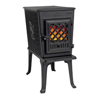
Jøtul F 602 V3
Catalytic Wood Heater
Installation and Operating Instructions
for the United States and Canada
„ The Jøtul F 602 V3 wood stove is listed
to burn solid wood only. Do not burn
any other fuels.
„ Read this entire manual before you
install and use your new room heater.
Failure to follow instructions may
result in property damage, bodily
injury, or even death.
„ Save these instructions for future
reference and make them available to
anyone using or servicing this wood
heater.
„ This wood heater contains a catalytic
combustor that requires periodic
inspection and maintenance for
proper operation. See this manual
for specific maintenance information.
It is against federal regulations to
operate this wood heater in a manner
inconsistent with the operating
instructions in this owner's manual, or
if the catalytic element is deactivated
or removed.
Une version française de ce manuel est disponible au-
près de votre revendeur et sur le site www. jotul.ca.
Advertisement
Table of Contents

Related Manuals for Jøtul F 602 V3


Summary of Contents for Jøtul F 602 V3
- Page 1 Jøtul F 602 V3 Catalytic Wood Heater Installation and Operating Instructions for the United States and Canada „ The Jøtul F 602 V3 wood stove is listed to burn solid wood only. Do not burn any other fuels. „ Read this entire manual before you install and use your new room heater.
-
Page 2: Table Of Contents
130196-1 F 602 V3 October 2024 Accessories Table of Contents Combustion Specifications, The following accessories, specifically designed for the Building Codes, Jøtul F 602 V3 wood stove, are available from your Jøtul Safety Notices ............... 3-4 authorized dealer. 1. Installation Rear Heatshield - HS-50 1.1 Assembly before Installation ......... 5 A stove rear heatshield has been specifically designed for the 1.2 Rear Heat Shield Installation ........ 6 Jøtul F 602 V3 to reduce clearances off the rear of the stove to 1.3 Fresh Air Adaptor Installation........ 7 combustible materials. Use of the heatshield does not affect the 2. Chimney and Connector Requirements clearance off the sides of the appliance. -
Page 3: Combustion Specifications
This manual describes the installation and EPA Validated Efficiency: operation of the Jøtul F 602 V3 catalytic equipped High Heat Value and Low Heat Value efficiencies are wood heater. This heater meets the 2020 U.S. determined per the CSA B415.1-10 test method. The difference Environmental Protection Agency’s crib wood... -
Page 4: Safety Notices
130196-1 F 602 V3 October 2024 Safety Notices See Sect. 5.0 of this manual for important information regarding the safe, proper, and most efficient operation of • BURN SOLID, NATURAL WOOD FUEL ONLY. DO NOT BURN ANY your stove. OTHER FUEL. Always follow the guidelines presented in this manual • DO NOT USE CHEMICALS OR FLUIDS TO START A FIRE. DO NOT BURN GARBAGE OR FLAMMABLE FUELS. -
Page 5: Installation
130196-1 F 602 V3 October 2024 1. Installation 1.1 Assembly Before Installation 2.1 Inspect Contents If this solid fuel room heater is not properly installed, Inspect the stove for damage. Contact your dealer immediately if any a house fire may result. For your safety, follow the damage is found. Do not install the stove if any damage is evident. n directions. Use only specified components. The... -
Page 6: Rear Heat Shield Installation
130196-1 F 602 V3 October 2024 1.4 Rear Heatshield HS-50 Installation 1. Remove the two smoke outlet cover screws and remove the cover from the top of the stove. The F 602 V3 Heat Shield can only be used in the top exit 2. Reaching through the outlet opening, use the 10 mm mode. In order to install the heat shield, the flue collar must wrench and screwdriver to remove the flue collar nuts and first be moved from the rear to the top, and the outlet cover screws. Keep the nuts for later use. moved from the top to the rear. 3. Install the flue collar on the top of the stove using the Kit Contents: screws previously removed. -
Page 7: Fresh Air Adaptor Installation
130196-1 F 602 V3 October 2024 1.5 Fresh Air Adaptor 156408 Installation *Note: Requires Rear Heat Shield HS-50 Kit Contents: • #8 x 1/2” Sheet Metal Screws (4) • Fresh Air Adaptor Valve Assembly Materials Required: • 4” dia. flexible metallic conduit for fresh air • Weather resistant wall termination cap • 1/4” mesh rodent screen • 3 self-tapping sheet metal screws or 4” dia. hose clamp Tools Required to install all of the above: • 1/4 in. socket driver • spade screwdriver • power drill • 1/8” dia. drill bit • 4” dia. sheet metal hole saw The adaptor valve assembly simply attaches to the back of the heat shield using the sheet metal screws provided. Orient the valve assembly as shown in the illustration. Heat shields in- corporate the necessary duct and fastener holes. Twist the air duct knock-out to remove it. Fig. 1.5... -
Page 8: Chimney And Connector Requirements
130196-1 F 602 V3 October 2024 2. Chimney and Chimney • No part of the chimney connector may pass through an Connector Requirements attic or roof space, closet or other concealed space, or through a floor or ceiling. 2.1 Chimney Connector • All sections of the chimney connectors must be accessible for cleaning. The chimney connector is a single walled pipe used to • Where passage through a wall or partition of connect the stove to the chimney. For use with the combustible construction is desired, the installation Jøtul F 602 V3, the chimney connector must be 6” (152mm) must conform with NFPA 211 and is also addressed in in diameter, with a minimum thickness of 24 gauge black this manual. -
Page 9: Masonry Chimneys
130196-1 F 602 V3 October 2024 2.3 Masonry Chimneys Chimney Considerations When choosing a chimney type and location in the A masonry chimney must conform to the following house, keep this in mind: it is the chimney that makes the guidelines: stove work, not the stove that makes the chimney work. • The chimney flue size should not be less than the cross- The chimney allows the temperature difference between sectional area of the stove flue collar. inside and outside air to create suction, called “draft”, • The cross-sectional area of the flue of a chimney with no which pulls air through the stove necessary to support walls exposed to the outside below the roofline shall not combustion. Since draft is the force which moves air from be more than three times the cross-sectional area of the the stove up through the chimney, its strength is critical stove flue collar. to proper stove function. Besides air pressure differential, draft strength is affected other factors including: • The cross-sectional area of a chimney flue having one • chimney condition and height or more walls exposed to the outside below the roofline • surrounding construction, other buildings shall not be more than two times the cross-sectional * nearby trees, local geography area of the stove flue collar. -
Page 10: Prefabricated Chimneys
130196-1 F 602 V3 October 2024 2.4 Prefabricated Chimneys 2.6 Wall Pass-throughs A prefabricated metal chimney must be tested and When your installation unavoidably requires the chimney listed for use with solid fuel burning appliances to High connector to pass through a combustible wall to reach the Temperature (HT) Chimney Standard UL 103 for the U.S and chimney, always consult your local building officials, and be sure any materials to be used have been tested and ULC S629 in Canada. listed for wall pass-throughs. The manufacturer’s installation instructions must be followed precisely. Always maintain the proper clearance In the U.S: to combustibles as established by the pipe manufacturer. This clearance is usually a minimum of 2” (56mm), although The National Fire Protection Association’s publication, it may vary by manufacturer or for certain chimney NFPA 211, Standard for Chimneys, Fireplaces, Vents and components. Solid Fuel Burning Appliances permits four methods for passing through a combustible wall. Before proceeding 2.5 Chimney Height with any method be sure to consult with your local building officials to discuss any local code requirements. The minimum chimney height is 15 feet (4.57 m). The... -
Page 11: Connecting To The Chimney
130196-1 F 602 V3 October 2024 3. Connecting to the Chimney 3.1 Masonry Chimney Thimble In Canada: When connecting the stove to a masonry chimney through The installation must conform to CAN/CSA-B365, Installation a “thimble” (the opening through the chimney wall to the Code for Solid Fuel Burning Appliances and Equipment. Before proceeding be sure to consult your local building inspector. flue), the thimble must be lined with ceramic tile or metal Common Method: and be securely cemented in place. See fig. 2.3. -
Page 12: Hearthmount Into A Masonry Fireplace
Floor Protector Fig. 3.2. Fireplace chimney construction. DO NOT INSTALL IN ANY FIREPLACE. The F 602 V3 may be vented through a masonry fireplace as described above but the stove must be installed IN FRONT of the fireplace opening. -
Page 13: Clearances To Combustibles
28 1/2”W X 45 1/2”D. See figure 4.2. 28 1/2”W X 43 1/2”D . See figure 4.1. Fig. 4.2. F 602 V3 Hearth Dimensions Canada. A is 8” B is 16” Fig. 4.1. F 602 V3 Hearth Dimensions USA. A is 8” B is 16”... -
Page 14: Clearances To Walls And Ceilings
Refer to NFPA 211, Standard for Chimneys, Fireplaces, If you are not sure of the combustible nature of a Vents and Solid Fuel Burning Appliances, for acceptable material, consult your local fire officials. Contact your materials, proper sizing and construction guidelines. local building officials about restrictions and installation Jøtul F 602 V3 Rear Heatshield Kit HS-50 requirements in your area. This shield is specifically approved for use to reduce clearances on this appliance only. No other heat shield “Fire Resistant” materials are considered combustible; may be used. they are difficult to ignite, but will burn. “Fire-rated” sheet rock is also considered combustible. -
Page 15: Alcove Installation
130196-1 F 602 V3 October 2024 4.4 Alcove Installation Fig. 4.4. Alcove unprotected wall clearances. This appliance may be installed in an alcove provided: (See figures 4.4 and 4.5.) Alcove Installation 1. The stove must be installed with listed, double-wall With stove heat shield pipe. 2. In a protected alcove installation both side walls and rear wall must be protected per NFPA 211. The wall protection must be elevated 1”(24,5mm) from the floor and at least 1” (24,5mm)off the combustible wall to allow for cooling air-flow. 3. The height of the wall protection including the bottom A: 55” - (140 cm) B: 15” - (39,5 cm) air space must be 48”(1219mm). -
Page 16: Clearance Charts
130196-1 F 602 V3 October 2024 Stove clearances Unprotected surfaces Protected surfaces (NFPA 211) Top vent/vertical Side Rear Corner Side Rear Corner Single wall pipe 21” 13.5” 13” 13” 11” 9” W/out rear heatshield 535mm 345mm 330mm 330mm 280mm 230mm Single wall pipe 21” 11” 11”... - Page 17 130196-1 F 602 V3 October 2024 Parallel installation with wall shield Fig. 4.11 Clearance to Adjacent Combustibles Combustible wall Fig. 4.7 Wall shield • Must be 27” wide and centered behind the stove. • Must be 1” off the wall and 1” off the floor. • With single wall pipe, A: 21” (53,5cm) the shield must be B: 13,5 ” (34,5 cm) 49” high measured off the floor. • With double wall pipe, the shield must be 37” high measu- red off the floor.
-
Page 18: Operation
130196-1 F 602 V3 October 2024 5. Operation Fireplace Mantel and Trim Clearance Fig. 4.14 Please read the following section completely before building a fire in your new Jøtul F 602 V3. DO NOT OVERFIRE THIS HEATER. THE MAXIMUM RECOMMENDED OPERATING TEMPERATURE OF THE COMBUSTOR IS 1600°F (870°C). DAMAGE CAN OCCUR TO THE COMBUSTOR IF IT EXCEEDS 1750°F (954°C) FOR EVEN BRIEF PERIODS OF TIME. -
Page 19: Co Emissions
• Paper products, junk mail, cardboard, plywood, or particle Use dry wood. board. (The prohibition against burning these materials The F 602 V3 is designed to burn natural wood only. does not include the use of fire starters made from paper, Higher efficiencies and lower emissions generally result cardboard, saw dust, wax or similar substances for the when burning air-dried, seasoned hardwoods, as opposed purpose of starting a fire.) -
Page 20: Stove Control - Functions And Settings
Primary Air is manually regulated by a sliding valve located in the load door under the glass pane which Door Latch remains slightly open. The valve position controls the volume of primary air entering the firebox and thereby affects fire intensity, heat output and burn time. Primary Air Valve: air is directed to the main body of the fire through that air Left = Closed, Minimum Fire Middle = Medium Fire inlet. Right = Full Open, Maximum Fire Secondary air is automatically regulated to promote Fig. 5.3. Stove-top Thermometer locations combustion of volatile gas that would otherwise be exhausted to the atmosphere unburned. The secondary air inlet is located at the back of the stove where a temperature-sensitive bimetal coil continuously varies the volume of air introduced to fire. This air is preheated as it passes over the back and top of the firebox, directed to the secondary combustion baffle and delivered to the catalytic combustor. Fig. 5.1. F 602 V3 Combustion air flow. -
Page 21: Stove Top Thermometer
130196-1 F 602 V3 October 2024 The combustor maintains the high temperatures 5.6 Using the Combustor Monitor necessary to burn volatile gas that would otherwise pass unburned into the atmosphere. When the combustor is functioning, no smoke will be observed exiting the Each installation has unique physical and environmental chimney. This is evidence that the stove is operating in characteristics that will affect stove performance. Other the so-called ”sweet-spot” wherein optimum efficiency is variables affecting combustion efficiency are cordwood realized. species and moisture content. Taking those variables... -
Page 22: Stove Break-In Procedure
130196-1 F 602 V3 October 2024 2. Take the magnet off of Combustor Monitor and replace it in the correct orientation as shown in figures 5.6-5.8 Insert the Combustor Monitor fully into the hole with the 3. Fig. 5.6. Remove magnet from current orientation magnet attaching to the cast iron side plate as shown in figure 5.5. Seated within the right side directly behind the catalytic element, the Combustor Monitor accurately responds to combustion activity. Secondary combustion takes place at temperatures between 500°F (260°C) and 1200°F (260°C - 649°C). Temperatures can reach as high as 1400°F to 1500°F (760°C -816°C). The primary air valve should remain at the fully open Incorrect setting, (to the Right), at least until the monitor registers Orientation 500°F (260°C). Maintain that temperature for 15-20 minutes before adjusting the primary air lever to Medium Low - Medium High settings. The optimum temperature range for most efficient combustion is between 500°F and 800° Fig. 5.7. Orient magnet (260°C -371°C). Chimney draft should be in the .05 - 1.0 w.c. range. The so-called “sweet spot” combustion zone is best maintained at those temperatures. However it is not uncommon for combustion temperatures to reach over 1,400°F (760°C). -
Page 23: Starting And Maintaining A Fire
130196-1 F 602 V3 October 2024 and allow the stove to cool to room temperature. 5.9 Creosote and Soot Formation 2. Light a second fire, allowing the stove to reach a maximum and the Need for Removal surface temperature of 400°F (204°C) for 1 hour. 3. Cool the stove to room temperature. When wood is burned slowly or when burning green wood, 4. Light a third fire and gradually allow the stove to reach and it produces tar and other organic vapors which combine maintain a surface temperature of 500°F (260°C). with expelled moisture to form creosote. These creosote 5. Cool stove to room temperature. This completes the vapors condense in the relatively cool chimney flue of a “break-in” procedure. slow burning fire. The creosote that accumulates in the flue is highly flammable and is the fuel of chimney fires. To NOTE: Keep the stove under 400°F (204°C) surface prevent a chimney fire, the creosote needs to be removed temperature during any “break-in fire”, with the exception... -
Page 24: Adding Fuel
130196-1 F 602 V3 October 2024 6. Maintenance 5.10 Adding Fuel Reload the stove while a bed of hot embers still exists, Regular maintenance will prolong the life of your stove and Follow this procedure: ensure satisfactory performance. • Always wear gloves when tending to the stove. Warning: Use only Jøtul authorized parts. Do • Push the air control lever to the full open position (far NOT use substitute glass. right). • To minimize any smoke spillage, open the door slightly 6.1 Annual Stove Inspection before opening fully. This will allow air flow to stabilize within the firebox and chimney flue. • Empty stove of all soot and ashes. Only use a vacuum for this job if the vacuum is specifically designed to handle • Use a stove tool or poker to distribute the hot embers... -
Page 25: Enamel Care
130196-1 F 602 V3 October 2024 Glass retainers should be tightened gradually, following an 6.5 Glass Care alternating pattern similar to tightening vehicle lug nuts. Do not over-tighten. It may be necessary to retighten once Cleaning again after the stove has been burned and the new gasket While the air wash and high temperatures of normal has seated. operation will combine to keep the glass free of heavy Fig. -
Page 26: Combustion System Maintenance
130196-1 F 602 V3 October 2024 Following is a list of items that should be checked on a periodic basis: 6.7 Combustion System • The combustor should be visually inspected at least three Maintenance times during the heating season to determine if physical degradation has occurred. The combustor can be visually WARNING: BURNING JUNK MAIL OR inspected for damage and fly ash accumulation simply by opening the front door and looking up at the catalyst COPIOUS AMOUNTS OF NEWSPRINT TO located above the secondary combustion baffle. Use a START THE FIRE CAN ACCELERATE FLY flashlight or head lamp to aid inspection. - Page 27 130196-1 F 602 V3 October 2024 Use the following instructions for combustor replacement: 1. Use the 10mm socket wrench with extension to remove the M6 flange nut located behind the exhaust diverter inside the stove as in figure 6.3. 3. Lift the front of the cookplate and pull forward to remove. 4. Wearing gloves, use both hands to carefully remove the Insulation Gasket from the firebox. Figure 6.5. 5. Simply lift the catalytic combustor to remove it from the compartment channel. Figure 6.6. 6. Reassemble the catalytic combustion components in the reverse order used to remove them. Fig. 6.5. Insulation gasket Fig. 6.6. Lift combustor from the chamber. Fig.6.4. Remove the cook plate from stove.
-
Page 28: Illustrated Parts Breakdown
130196-1 F 602 V3 October 2024 7. F 602 V3 Illustrated Parts Breakdown Purchase replacement parts only from a Jøtul Authorized dealer. -
Page 29: Part Numbers
130196-1 F 602 V3 October 2024 7. F 602 V3 Parts List No. No. Description Description Part No. Part No. No. No. Description Description Part No. Part No. 45. Air Slider ..........10315592 Cook Plate, F 602 V3 ......105056 47. Front panel ........10168392 Gasket, Round, LD2-375 ......225695 48. Bottom Plate ........10166592 Screw, M6 x 12, Phillips Pan Head ..118042 50. Leg .............10081792 Air Deflector ..........103153... -
Page 30: Exclusions And Limitations
130196-1 F 602 V3 October 2024 8. Jøtul F 602 V3 Woodburning Product Warranty Exclusions and Limitations Notice: This warranty is void if installation or service is performed by someone other than an authorized installer or service agency, Effective January 1, 2019 or if installation is not in conformance with the installation and operating instructions contained in this owner’s manual or local This warranty policy applies to wood-burning products identified and/or national fire and building regulations. A listing of local by Jøtul trade name, as set forth below. authorized installers, service agencies and gas suppliers can be obtained from the National Fireplace Institute at http://www. A. LIMITED LIFETIME WARRANTY, parts only: nficertified.org/. Jøtul North America Inc. (JØTUL) warrants, to the original retail purchaser, that those baffle and air manifold components of This warranty does not cover the following: the Jøtul Stove or Fireplace Insert specified above will be free of... - Page 31 130196-1 F 602 V3 October 2024 Some states do not allow the exclusion or limitation of incidental or consequential damages, or limitations on the length of implied warranties. Therefore, the above exclusions or limitations may not apply to you. This warranty gives you specific legal rights, and you may have other rights, which vary from state to state. JØTUL reserves the right to discontinue, modify or change the materials used to produce the Jøtul stove or fireplace. JØTUL shall have the right to replace any defective component with substitute components determined by JØTUL to be of substantially equal quality and price. The dollar value of JØTUL’s liability for breach of this warranty shall be limited exclusively to the cost of furnishing a replacement component. JØTUL shall not in any event be liable for the cost of labor expended by others in connection with any defective component. Any costs or expenses beyond those expressly assumed by JØTUL under the terms of this warranty shall be the sole responsibility of the owner(s) of the Jøtul or stove or fireplace. No dealer, distributor, or other person is authorized to modify, augment, or extend this limited warranty on behalf of JØTUL. NO MODIFICATION OR CHANGE TO THIS WARRANTY WILL BE EFFECTIVE UNLESS IT IS MADE IN A WRITTEN DOCUMENT MANUALLY SIGNED BY AN AUTHORIZED OFFICER OF JØTUL.
- Page 32 130196-1 F 602 V3 October 2024 Jøtul High Flow TM Catalytic 5. Return the defective combustor to your local Jøtul Authorized Dealer who will submit a Combustor 10 – Year limited warranty claim on your behalf. All claims must Warranty be accompanied by proof of purchase showing the name of the selling dealer, date of purchase, Jøtul stove or insert model and the serial number of the unit, along with the consumer’s name. All claims must be accompanied by clear photos of Jøtul North America Inc. warrants to the the damaged combustor. consumer who purchases a Jøtul High Flow Combustor as a component in an EPA – Certified 6. Related cost of replacement such as Jøtul solid fuel appliance, 100 % against defects installation, travel, and shipping are excluded in material and workmanship for a period of 10 and the responsibility of the consumer. years from the date of purchase. 7. Return of the original Jøtul High Flow Combustor to Jøtul North America may be required. Conditions and Exclusions: 8. Any subsequent replacement combustor 1. The Jøtul High Flow Combustor 10 Year...
- Page 33 130196-1 F 602 V3 October 2024...
- Page 34 130196-1 F 602 V3 October 2024...
- Page 35 130196-1 F 602 V3 October 2024...
- Page 36 130196-1 F 602 V3 October 2024 Protect your investment! Don’t miss out on the benefits of warranty coverage. Scan this QR code or visit jotul.com/warranty today to ensure peace of mind and timely support. Jøtul pursues a policy of continuous product development. Products supplied may therefore differ in specification, color and type of accessories from those illustrated and described in this manual. For Your Records... Record the following information to help your dealer determine what you will need should your stove ever require parts or service.
Need help?
Do you have a question about the F 602 V3 and is the answer not in the manual?
Questions and answers