
Related Manuals for METREL SMARTEC MI 3121H


Summary of Contents for METREL SMARTEC MI 3121H
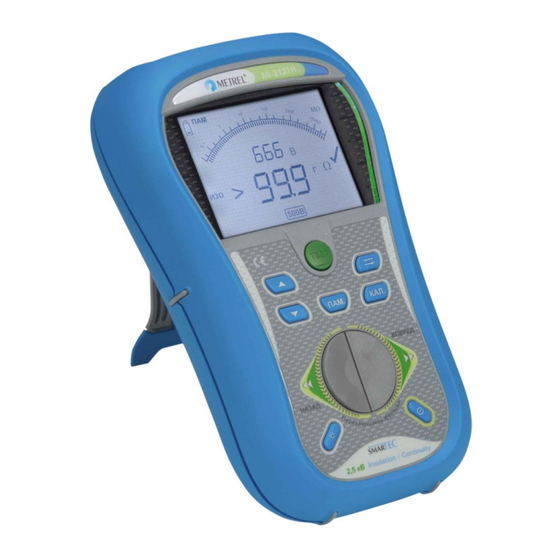
- Page 1 2,5 kV Insulation / Continuity MI 3121H Instruction manual Version 1.2.4, Code no.: 20 751 674...
- Page 2 Mark on your equipment certifies that it meets requirements of all subjected EU regulations. Hereby, Metrel d.d. declares that the MI 3121H is in compliance with subjected EU directive. The full text of the EU declaration of conformity is available at the following internet address http://www.metrel.si/DoC...
-
Page 3: Table Of Contents
MI 3121H Smartec 2,5 kV Insulation / Continuity Table of contents Preface ......................... 5 Safety and operational considerations ..............6 Warnings and notes ....................6 Battery and charging ..................... 8 2.2.1 New battery cells or cells unused for a longer period ........9 2.2.2 Auto Power Off .................... - Page 4 MI 3121H Smartec 2,5 kV Insulation / Continuity Table of contents Periodic calibration ....................37 Service ........................ 37 Technical specifications ..................38 Insulation resistance .................... 38 Continuity ......................39 8.2.1 Resistance RLOW ..................39 8.2.2 Resistance CONT ..................39 Voltage, frequency ....................39 8.3.1 Voltage ......................
-
Page 5: Preface
In order for operator to be familiar enough with performing measurements in general and in typical applications it is advisable to read Metrel handbook Guide for testing and verification of low voltage installations. The instrument is equipped with all necessary accessories for comfortable testing. -
Page 6: Safety And Operational Considerations
MI 3121H Smartec 2,5 kV Insulation / Continuity Warnings and notes 2 Safety and operational considerations 2.1 Warnings and notes In order to reach high level of operator’s safety while carrying out various tests and measurements using Smartec 2,5 kV Insulation / Continuity test equipment, as well as to keep the equipment undamaged, it is necessary to consider the following general warnings: Warning on the instrument means »Read the Instruction manual with... - Page 7 MI 3121H Smartec 2,5 kV Insulation / Continuity Warnings and notes Notes related to measurement functions: General If there is any irregular condition on input terminals then the selected measurement ❑ can't be performed. Insulation resistancecontinuity measurements shall be performed on de- ❑...
-
Page 8: Battery And Charging
MI 3121H Smartec 2,5 kV Insulation / Continuity Battery and charging 2.2 Battery and charging The instrument uses six AA size alkaline or rechargeable Ni-Cd or Ni-MH battery cells. Nominal operating time is declared for cells with nominal capacity of 2100 mAh. Battery condition is always present on the display when the instrument is turned on. -
Page 9: New Battery Cells Or Cells Unused For A Longer Period
MI 3121H Smartec 2,5 kV Insulation / Continuity Battery and charging 2.2.1 New battery cells or cells unused for a longer period Unpredictable chemical processes can occur during charging of new battery cells or cells that were unused for a longer period (more than 3 months). Ni-MH and Ni-Cd battery cells are affected to capacity degradation (sometimes called as memory effect). -
Page 10: Standards Applied
MI 3121H Smartec 2,5 kV Insulation / Continuity Standards applied 2.3 Standards applied The MI 3121H Smartec 2,5 kV Insulation / Continuity instrument is manufactured and tested according to the following regulations, listed below. Electromagnetic compatibility (EMC) Electrical equipment for measurement, control and laboratory use – EMC requirements EN 61326 Class B (Hand held equipment used in controlled EM environments) -
Page 11: Instrument Description
MI 3121H Smartec 2,5 kV Insulation / Continuity Front panel 3 Instrument description 3.1 Front panel Figure 3.1: Front panel Legend: 1 LCD Custom display with backlight. 2 TEST Starts / stops a measurement. 3 UP Modifies selected parameter. 4 DOWN 5 MEM Store / recall / clear tests in memory of instrument. -
Page 12: Connector Panel
MI 3121H Smartec 2,5 kV Insulation / Continuity Connector panel 3.2 Connector panel Figure 3.2: Connector panel Legend: 1 Test connector Measuring inputs / outputs, connection of measuring cables. Protects from simultaneous access to test connector and power 2 Protection cover supply adapter socket / communication connectors. -
Page 13: Back Panel
MI 3121H Smartec 2,5 kV Insulation / Continuity Back site 3.3 Back panel Figure 3.3: Back site Legend: Side belt Battery compartment cover Fixing screw for battery compartment cover Back panel information label Holder for inclined position of the instrument Magnet for fixing instrument close to tested item Figure 3.4: Battery compartment Legend:... -
Page 14: Display Organization
MI 3121H Smartec 2,5 kV Insulation / Continuity Display organization 3.4 Display organization Function field Result field Analog results display Test voltage selection field Figure 3.5: Typical display Message field CAL LIM MEM RCL Auxiliary monitor Battery indication 3.4.1 Function field The function field displays currently selected function. -
Page 15: Message Field
MI 3121H Smartec 2,5 kV Insulation / Continuity Display organization Numeric readout of measurement result Measurement result is inside pre-set limits (PASS). Measurement result is out of pre-set limits (FAIL). Analog presentation of measured result. … 3.4.3 Message field In the message field, different warnings and messages are displayed. Warning! Read the User Manual with special care! Warning! Dangerous voltage is applied to the test terminals. -
Page 16: Battery Indication
MI 3121H Smartec 2,5 kV Insulation / Continuity Display organization 3.4.5 Battery indication In the menu line, the name of the selected function is displayed. Additional information about active cursor / TEST keys and battery condition are shown. Battery capacity indication. Low battery. -
Page 17: Instrument Set And Accessories
MI 3121H Smartec 2,5 kV Insulation / Continuity Instrument set and accessories 3.5 Instrument set and accessories 3.5.1 Standard set Instrument MI 3121H NiMH battery cell, type AA, 6 pcs ❑ ❑ Instruction manual Power supply adapter ❑ ❑ Calibration certificate CD with instruction manual, and ❑... -
Page 18: Instrument Operation
MI 3121H Smartec 2,5 kV Insulation / Continuity Function selection 4 Instrument operation 4.1 Function selection For selecting test function, the FUNCTION SELECTOR shall be used. Keys: Select test / measurement function: FUNCTION <VOLT> Voltage and frequency and phase sequence. ❑... -
Page 19: Settings
MI 3121H Smartec 2,5 kV Insulation / Continuity Settings 4.2 Settings The instrument offers additional functions by the following combinations of the keys during power on. Combinations are: UP + ON Opens settings menu. TAB + ON Resets the instrument to initial factory settings. Different instrument options can be set in the settings menu. -
Page 20: Date And Time
MI 3121H Smartec 2,5 kV Insulation / Continuity Settings The default setup is listed below: Instrument setting Default value Function Parameters / limit value Sub-function Insulated resistance No limit, Utest = 500 V Continuity RLOW RLOW No limit CONT No limit Note: Initial settings (reset of the instrument) can be recalled also if the TAB key is ❑... -
Page 21: Measurements
MI 3121H Smartec 2,5 kV Insulation / Continuity Insulation resistance 5 Measurements 5.1 Insulation resistance 5.1.1 Insulation resistance measuring procedure Insulation resistance measurement is performed in order to assure safety against electric shock through insulation. It is covered by the EN 61557-2 standard. Typical applications are: Insulation resistance between conductors of installation, ❑... - Page 22 MI 3121H Smartec 2,5 kV Insulation / Continuity Insulation resistance Test circuits for insulation resistance mains voltage closed switched off switches loads disconnected Figure 5.2: Connection of 2-wire test lead Figure 5.3: Connection of optional 3-wire test lead (A 1319) Insulation resistance measuring procedure Select the function using the BACK / NEXT keys of function selector.
-
Page 23: The Dar And Pi Diagnostic
MI 3121H Smartec 2,5 kV Insulation / Continuity Insulation resistance Figure 5.4: Example of insulation resistance measurement result Displayed results: Insulation resistance – value, Insulation resistance – analog presentation, Test voltage – actual value. Test voltage – nominal value. 5.1.2 The DAR and PI diagnostic The DAR and PI diagnostic is automatically calculated during insulation measurements. -
Page 24: Guard Terminal
For additional information regarding PI and DAR diagnostic, please refer to Metrel’s handbook Modern Insulation Testing. 5.1.3 Guard terminal The purpose of the GUARD terminal is to lead away potential leakage currents (e.g. - Page 25 MI 3121H Smartec 2,5 kV Insulation / Continuity Insulation resistance + OUT + OUT -OUT GUARD -OUT Figure 5.10: Connection of GUARD terminal to measured object where: Ut ..Test voltage ..Leakage current (resulted by surface dirt and moisture) ..
-
Page 26: Resistance Of Earth Connection And Equipotential Bonding
MI 3121H Smartec 2,5 kV Insulation / Continuity Continuity 5.2 Resistance of earth connection and equipotential bonding The resistance measurement is performed in order to assure that the protective measures against electric shock through earth bond connections are effective. Two sub-functions are available: RLOW - Earth bond resistance measurement according to EN 61557-4 (200 mA), ❑... -
Page 27: Continuous 7 Ma Resistance Measurement Cont
MI 3121H Smartec 2,5 kV Insulation / Continuity Continuity Resistance to earth connection and equipotential bonding measurement procedure Select continuity function (RLOW or CONT) using the BACK / NEXT keys of ❑ function selector. Set sub-function to RLOW. ❑ Enable and set limit (optional). ❑... - Page 28 MI 3121H Smartec 2,5 kV Insulation / Continuity Continuity Test circuit for CONT resistance measurement Figure 5.14: 2-wire test lead application Continuous resistance measurement procedure Select continuity function RLOW CONT using the BACK / NEXT keys of ❑ function selector. Set sub-function CONT.
-
Page 29: Compensation Of Test Leads Resistance
MI 3121H Smartec 2,5 kV Insulation / Continuity Continuity 5.2.3 Compensation of test leads resistance This chapter describes how to compensate for test leads resistance in both continuity functions (RLOW and CONT). Compensation is required to eliminate the influence of test leads resistance and the internal resistances of the instrument on the measured resistance. -
Page 30: Voltage And Frequency
MI 3121H Smartec 2,5 kV Insulation / Continuity Voltage and Frequency 5.3 Voltage and frequency In the VOLT menu the measured voltage and frequency are displayed. See 4.1 Function selection for instructions on key functionality, Figure 5.17: Voltage and frequency display Circuits for voltage measurement Figure 5.18: Connection of 2-wire test lead... - Page 31 MI 3121H Smartec 2,5 kV Insulation / Continuity Voltage and Frequency Voltage measurement procedure Select the VOLT function. ❑ Connect test lead to the instrument. ❑ Connect test leads to the tested object (see Figure 5.18). ❑ Store voltage measurement result (optional). ❑...
-
Page 32: Data Handling
MI 3121H Smartec 2,5 kV Insulation / Continuity Memory organization 6 Data handling 6.1 Memory organization Measurement results together with all relevant parameters can be stored in the instrument’s memory. 6.2 Data structure The instrument’s memory place is divided into 2 levels each containing 199 locations. The number of measurements that can be stored into one location is not limited. -
Page 33: Storing Test Results
MI 3121H Smartec 2,5 kV Insulation / Continuity Storing test results 6.3 Storing test results After the completion of a test, the results and parameters are ready for storing (MEM is displayed with result). By pressing the MEM key, the user can store the results. Keys in save test menu - data structure field: Selects the location element (Object / Location) UP / DOWN... -
Page 34: Clear / Recall Options
MI 3121H Smartec 2,5 kV Insulation / Continuity Clear / Recall 6.5 Clear / recall options Press the MEM key in a main function menu for few seconds to activate possibility for clearing or recalling results. Figure 6.3: Entering menu for recall / clear options on stored results Keys in recall / clear memory menu: Opens menu to clear result at currently selected location. -
Page 35: Clearing Individual Results At Selected Location
MI 3121H Smartec 2,5 kV Insulation / Continuity Clear / Recall Figure 6.5: Clearing memory in progress 6.5.2 Clearing individual results at selected location After selection of CLEAR result, the instrument will display the following: Figure 6.6: Clear measurements menu Keys in clearing individual results menu (data structure field selected): Selects the location element (Object / Location). -
Page 36: Communication
MI 3121H Smartec 2,5 kV Insulation / Continuity Communication 6.6 Communication Stored results can be transferred to a PC. A special communication program on the PC automatically identifies the instrument and enables data transfer between the instrument and the PC. There are two communication interfaces available on the instrument: USB or RS 232. -
Page 37: Maintenance
MI 3121H Smartec 2,5 kV Insulation / Continuity Maintenance 7 Maintenance Unauthorized persons are not allowed to open the Smartec 2,5 kV Insulation / Continuity instrument. There are no user replaceable components inside the instrument, except the fuse and battery under rear cover. 7.1 Fuse replacement There is a fuse under back cover of the Smartec 2,5 kV Insulation / Continuity instrument. -
Page 38: Technical Specifications
MI 3121H Smartec 2,5 kV Insulation / Continuity Technical specifications 8 Technical specifications 8.1 Insulation resistance Insulation resistance (nominal voltages 100 V and 250 V Measuring range according to EN61557 is 0.15 M 999.9 M. Accuracy Measuring range (M) Resolution (M) 0.00 ... -
Page 39: Continuity
MI 3121H Smartec 2,5 kV Insulation / Continuity Technical specifications 8.2 Continuity 8.2.1 Resistance RLOW Measuring range according to EN61557 is 0.16 1999 . Accuracy Measuring range R () Resolution () 0.00 19.99 (3 % of reading + 3 digits) 0.01 20.0 ... -
Page 40: General Data
MI 3121H Smartec 2,5 kV Insulation / Continuity Technical specifications General data Power supply voltage ......9 V (61.5 V battery or accu, size AA) Operation .......... typical 13 h Charger socket input voltage .... 12 V 10 % Charger socket input current ..... -
Page 41: Appendix A - Accessories For Specific Measurements
MI 3121H Smartec 2,5 kV Insulation / Continuity Accessory for specific measurements 9 Appendix A - Accessories for specific measurements The table below presents standard and optional accessories required for specific measurement. The accessories marked as optional may also be standard ones in some sets. - Page 42 MI 3121H Smartec 2,5 kV Insulation / Continuity Accessory for specific measurements...
- Page 43 MI 3121H Smartec 2,5 kV Insulation / Continuity Accessory for specific measurements...
- Page 44 MI 3121H Smartec 2,5 kV Insulation / Continuity Accessory for specific measurements...
Need help?
Do you have a question about the SMARTEC MI 3121H and is the answer not in the manual?
Questions and answers