Advertisement
WWW.GAMAINC.COM
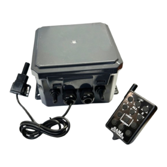
The LRF120V2PR1L is an RF receiver operating at a fixed frequency of 340 MHZ. It operates from 120VAC and provides
two polarity reversing output for use with a four/six lead AC motor. The receiver has provision for two normally-closed
limit switches, one for either direction for each motor output. The receiver is not designed to operate with any existing
hand or drum switch. The receiver is equipped with a manual toggle switch. An additional latching output is available for
connecting to a 120VAC light. Up to thirty, transmitters can be used to activate the receiver's relays. The receiver
has a terminal block for connecting the power and relay contacts. Each transmitter has a unique address that
is transmitted when a button is pressed. A "program" button is provided on the receiver to program the transmitter(s)
address into the receiver's memory. An LED on the receiver indicates the receiver's programming status and
illuminates when the receiver is energized. The receiver is encased in a waterproof enclosure. The operating range is
approximately 500 ft. Operating temperature range is 0°F to 160°F.
Polarity Reversing Outputs: The transmitter has two buttons assigned to each motor output. The up (^) button runs the
motor in one direction and the down (v) button runs the motor in the opposite direction. The reversing function
accomplished by reversing the phase on two of the four motor connections at the receiver output. Using the ALL buttons will
operate both motors simultaneously
Manual Switches: The receiver is equipped with 2 manual switches. This switch replaces any hand or drum switch
previously connected to the motor.
Limit Switches: The receiver is equipped with 2 limit switch provisions for each motor. This switch allows the user to stop
the motor using a normally closed limit switch on either direction. *NOTE: The system is shipped with the limit switches
disabled. To use the limit switches you will need to remove the jumper wire between the switch inputs.
Light Output: The light output is activated using the light button on the transmitter. Press the light button once to latch this
output on. Press the light button again to turn the light output off.
Maximum Ratings: Power for the receiver can be in the range of 100VAC to 132VAC. The relay contacts are rated at 20
Amps. Two separate AC inputs are provided, one for each motor.
LRF120V-2PR1L
Instruction Manual
Included in this Kit:
(1) LRF120V-2PR1L Receiver
(1) Keyfob Transmitter
(1) Long Range Antenna LRA340
Available accessories:
- Extra Long Range Antenna LRA-340
- Additional Transmitter RFT340-2PR1L
- Waterproof Transmitter RFT340-2PR1L-WP
- Rechargeable Transmitter RFT340-2PR1L-WPTX
- Package of 6 A23 12V Alkaline Batteries A23-6
- Clear Protective Transmitter Pouch ZLB-67
Page 1 REV O 11/13/24
Advertisement
Table of Contents

Related Manuals for GAMA Electronics LRF120V-2PR1L


Summary of Contents for GAMA Electronics LRF120V-2PR1L
- Page 1 LRF120V-2PR1L Instruction Manual WWW.GAMAINC.COM Included in this Kit: (1) LRF120V-2PR1L Receiver (1) Keyfob Transmitter (1) Long Range Antenna LRA340 Available accessories: - Extra Long Range Antenna LRA-340 - Additional Transmitter RFT340-2PR1L - Waterproof Transmitter RFT340-2PR1L-WP - Rechargeable Transmitter RFT340-2PR1L-WPTX - Package of 6 A23 12V Alkaline Batteries A23-6 - Clear Protective Transmitter Pouch ZLB-67 The LRF120V2PR1L is an RF receiver operating at a fixed frequency of 340 MHZ.
-
Page 2: Programming Instructions
LRF120V-2PR1L Instruction Manual WWW.GAMAINC.COM Programming Instructions Each transmitter has its own unique internal address along with the data as to which button is pressed and transmitted. The receiver needs to be programmed to respond only to the specific transmitter it is intended to operate with. The following steps configure the receiver to operate with a particular transmitter. -
Page 3: Wiring Instructions
LRF120V-2PR1L Instruction Manual WWW.GAMAINC.COM Wiring Instructions Prior to this, verify that there is no power at any of the motor terminals. 1. Disconnect or turn off the circuit breaker to remove power (if a hand or drum switch is connected to the motor it will need to be disconnected). -
Page 4: Truth Table
LRF120V-2PR1L Instruction Manual Schematic One of Two Motor Circuit Shown Truth Table K1 = Up or Down K4 = Up T2, T4 T1, T3 AC IN NEUT 120VAC IN AC IN LINE Relays shown in off position Page 4 REV O 11/13/24... -
Page 5: Troubleshooting
WWW.GAMAINC.COM Troubleshooting All remote-control systems shipped by GAMA Electronics are 100% functionally tested just prior to shipment. If your RF remote control system does not work out of the box, stops working or functions intermittently please take the following steps to resolve common issues. Please note that you must be 2-3 feet away from the receiver when operating the remote control. - Page 6 LRF120V-2PR1L Instruction Manual WWW.GAMAINC.COM Figure Figure Motor Name Motor Name STANDARD MOTOR WITH “T” NUMBERS See Figure 1 STANDARD MOTOR WITH “T” NUMBERS See Figure 1 STANDARD MOTOR WITH COLORED WIRE See Figure 2 STANDARD MOTOR WITH COLORED WIRE See Figure 2 See Figure 3 A.O Smith with L1, L2 Terminals &...
- Page 7 LRF120V-2PR1L Instruction Manual FIGURE 1 FIGURE 2 LINE IN LINE IN NEUTRAL IN NEUTRAL IN T1,T3 BLUE/ORANGE T2,T4 WHITE/YELLOW BLACK *USE WIRE NUTS TO CONNECT THE RECEIVER TO MOTOR WIRES FIGURE 3 FIGURE 4 LINE IN LINE IN NEUTRAL IN...
- Page 8 LRF120V-2PR1L Instruction Manual FIGURE 5 FIGURE 6 *MOTOR WIRES LINE IN BROWN & ORANGE LINE IN MUST BE CONNECTED NEUTRAL IN TO TERMINAL 3 NEUTRAL IN TERMINAL E TERMINAL 1 TERMINAL D TERMINAL 6 TERMINAL A TERMINAL 5 TERMINAL B...
- Page 9 LRF120V-2PR1L Instruction Manual FIGURE 9 FIGURE 10 LINE IN *USE WIRE NUTS LINE IN TO CONNECT THE RECEIVER NEUTRAL IN TO MOTOR WIRES NEUTRAL IN TERMINAL 1 TERMINAL 3 TERMINAL 1 MOTOR YELLOW & WHITE MOTOR RED TERMINAL 4 TERMINAL 2...
- Page 10 LRF120V-2PR1L Instruction Manual FIGURE 13 FIGURE 14 LINE IN LINE IN NEUTRAL IN NEUTRAL IN L2 (WHITE) L1 (BLUE) BLACK BLACK FIGURE 15 FIGURE 16 LINE IN LINE IN NEUTRAL IN WHITE NO CONNECTION (1) ORANGE (2) BLACK *4-NEUTRAL IN...
- Page 11 LRF120V-2PR1L Instruction Manual FIGURE 17 FIGURE 18 LINE IN LINE IN NEUTRAL IN NEUTRAL IN 1 BLUE/3 ORANGE NO CONNECTION T2, T4 2 WHITE/4 YELLOW *P2, T3-NEUTRAL 5 BLACK FROM AC INPUT 8 RED *P1-NEUTRAL FROM AC INPUT FIGURE 19...
- Page 12 LRF120V-2PR1L Instruction Manual FIGURE 21 FIGURE 22 LINE IN LINE IN P2, T3 ORANGE/P2 NO CONNECTION NO CONNECTION T2, T4 YELLOW/WHITE BLACK *P1-NEUTRAL AC INPUT *P1-NEUTRAL AC INPUT FIGURE 23 FIGURE 24 LINE IN LINE IN NEUTRAL IN BROWN P2, ORANGE T3...
- Page 13 LRF120V-2PR1L Instruction Manual FIGURE 25 FIGURE 26 LINE IN LINE IN BROWN/ORANGE WHITE (2) BROWN (7/P2) NO CONNECTION NO CONNECTION BLUE (1) YELLOW/WHITE ORANGE (3) BLACK (5) BLACK RED (8) *YELLOW (4)-AC INPUT NEUTRAL BLUE -AC INPUT NEUTRAL FIGURE 27...
- Page 14 LRF120V-2PR1L Instruction Manual FIGURE 29 FIGURE 30 LINE IN LINE IN NEUTRAL IN BLACK, YELLOW 3,4 (BLUE) NO CONNECTION 1,2 (WHITE) RED, BROWN WHITE BLACK BLUE/WHITE BLUE -AC INPUT NEUTRAL FIGURE 31 FIGURE 32 LINE IN LINE IN T3, P2...
- Page 15 LRF120V-2PR1L Instruction Manual FIGURE 33 FIGURE 34 LINE IN LINE IN NEUTRAL IN 2, 4, 7, 9 (JUMPER TO T1,T3) (WHITE, YELLOW) JUMPER TO NEUT. 2 (RED) (ORANGE, BLACK) 5 -AC INPUT NEUTRAL 4 (BLACK) - NO CONNECTION Page 15 REV O 11/13/24...
Need help?
Do you have a question about the LRF120V-2PR1L and is the answer not in the manual?
Questions and answers