Advertisement
Advertisement
Table of Contents

Related Manuals for Frico PCW Series


Summary of Contents for Frico PCW Series
- Page 1 Original instructions ..29 ..45 ..61...
- Page 2 160,5 160,5 [mm] [mm] [mm] [mm] PCW132S/134S PCW232S/234S PCW332S/334S 1205 PCW432S/434S 1205 PCW532S/534S 1420 1099 Vattenanslutning invändig gänga / Water connection inside thread/ Vanntilkobling innvendig gjenge PCW132S/134S DN15 G15 1/2” PCW232S/234S DN15 G15 1/2” PCW332S/334S DN15 G15 1/2” PCW432S DN20 G20 3/4”...
- Page 3 Montering / Mounting / Montering 1,5° 1,5° Fig.1...
- Page 4 Montering av inbyggd manöverpanel (PCR1 och PCR2) / Mounting of built-in control panels (PCR1 and PCR2) / Montering av innebygde kontrollenheter (PCR1 og PCR2) Fig.2: A-C...
- Page 5 Fig.2: D-G...
- Page 6 Montering av extern manöverpanel (PCEB, PCEC och PCEA) / Mounting of remote control panels (PCEB, PCEC and PCEA) / Montering av eksternt kontrollpanel (PCEB, PCEC og PCEA) AUTO AUTO AUTO AUTO ° ° 50 cm h = 150 cm AUTO AUTO °...
- Page 7 Montering av extern manöverpanel (PCEB) / Mounting of remote control panels (PCEB) / Montering av eksternt kontrollpanel (PCEB) DIN 503 13,5 cm 3 cm...
- Page 8 Montering av extern manöverpanel (PCEC) / Mounting of remote control panels (PCEC) / Montering av eksternt kontrollpanel (PCEC) DIN 503 135 mm 28 mm AUTO AUTO °...
- Page 9 Montering av extern manöverpanel (PCEA) / Mounting of remote control panels (PCEA) / Montering av eksternt kontrollpanel (PCEA) 60 mm 84 mm...
- Page 10 Vattenbatteri / Water coil / Vannbatteri Max. vattentemperatur in / Max. water temperature in: +85 °C Min. vattentemperatur in / Min. water temperature in: +5 °C Max. arbetstryck / Max. working pressure: 1000 kPA (10 bar) 2-rörsystem, 3-radigt batteri 4-rörsystem, 3-radigt samt 1-radigt batteri 2 pipe system, 3 row coil 4-pipe system, 3 row and 1 row battery 2-rørsystem, 3-raders batteri...
- Page 11 Dimensioneringstabeller, 3-radigt batteri, 2-rörsystem, värme Output charts water, 3 row coil, 2-pipe system, heating Effektdiagrammer, vann, 3-raders batteri, 2-rørssystem, varme Incoming air temperature 20 °C Water temperature Water temperature Water temperature 60/40 °C 55/35 °C 55/30 °C Type Output Water Pres.
- Page 12 Dimensioneringstabeller, 3-radigt batteri, 2-rörsystem, kyla. Luftfuktigh.: 50% Output charts water, 3 row coil, 2-pipe system, cooling. R.H. 50% Effektdiagrammer, vann, 3-raders batteri, 2-rørssystem, kjøling. Relativ fuktighet: 50 % Incoming air temperature 27 °C Water temperature Water temperature 7/12 °C 7/17 °C Type Output Output...
- Page 13 Dimensioneringstabeller, 3-rad. batteri-kyla, 1-rad. batteri-värme, 4-rörsystem Output charts water, 3 row coil-cooling, 1 row coil-heating, 4-pipe system Effektdiagrammer, vann, 3-raders batteri-kjøling, 1-rads batteri-varme, 4-rørssystem Incoming air temperature 24 °C Incoming air temperature 20 °C Water temperature 7/12 °C Water temperature 50/40 °C 3 row coil 1 row coil Cooling...
- Page 14 Tryckfallsdiagram över fläktkonvektor PCW / Water pressure drop over PCW water coil / Trykkfall over vannbatteri PCW 3-radigt batteri / 3 row coil / 3-raders batteri Tryckförlusten i diagrammet är beräknad för medeltemperaturen (T) 10 °C. För andra vattentemperaturen multipliceras tryckfallet med en faktor K.
- Page 15 Vattenregleringar / Water controls / Vannregulering PCVR13C /PCVR45 PCVR13C: PCW132S, PCW232S, PCW332S PCVR45: PCW432S, PCW532S ± 10 mm PCVR315 PCVR315: PCW134S, PCW234S, PCW334S, PCW434S, PCW534S ± 10 mm Item number Type Dimensions Valve Micrometric lockshield valve Ø Ø PCVR13C 19017 1/2"F 1/2"F 1/2"F...
- Page 16 PCVR213 /PCVR245 PCVR213: PCW132/134S, PCW232/234S, PCW332/334S PCVR245: PCW432/434S, PCW532/534S ± 10 mm Dimensions Valve Item number Type Main coil Additional coil Main coil Additional coil Ø Ø 11705 PCVR213 1/2"F 1/2" PCVR245 11706 3/4"F 1/2" Ordlista Vattenregleringar Glossary Water controls Ordliste Vannregulering Mått / Dimensions / Mål Ventil / Valve / Ventil...
- Page 17 Tryckfallsdiagram över ventiler / Pressure drop over valves / Trykkfallsdiagram over ventiler PCVR13C / PCVR45 Kvs 2 Kvs 2,5 Kvs 1,6 300 400 600 800 1000 2000 3000 4000 PCVR213 / PCVR245 Kvs 1,7 Kvs 2,8 300 400 600 800 1000 2000 3000 4000...
- Page 18 Tillbehör / Accessories / Tilbehør PCTV Item number Type 11699 PCTV 19015 PCSHL 19016 PCSHR 11694 PCSHL / PCSHR Type [mm] PCW132/134S PCW232/234S PCG332/334S PCG532/534S 1119...
- Page 19 Regleringar / Controls / Reguleringer PCR1 PCR2 ° ° PCEC PCEB PCEA PCPU Item number Type PCR1 11685 11686 PCR2 PCEB 452690 452691 PCEC PCEA 452692 452693 PCPU 11693...
- Page 20 PCR1 Utan ventil / Without valve / Uten ventil Temperature sensor Light blue PCR1 230V 50Hz 3 speed 230V 50Hz *Obs! Bygel *Note! Bridge *NB! Klemme Temperaturgivare / Temperature sensor / Temperaturmåler 3 hastigheter / 3 speed / 3 hastigheter Med begränsningstermostat / With low cut-out thermostat / Med begrensningstermostat...
- Page 21 Temperature sensor Light blue PCR1 Med 1 ventil / With 1 valve / Med 1 ventil PCR1 Temperature sensor Light blue 230V 50Hz 3 speed PCR1 *Obs! Bygel *Note! Bridge *NB! Klemme 230V 50Hz 230V 50Hz 3 speed 230V 50Hz Temperature sensor Med 2 ventiler / With 2 valves / Med 2 ventiler...
- Page 22 PCR2 Utan ventil / Without valve / Uten ventil 5 4 3 2 1 6 5 4 3 2 1 *Obs! Bygel *Note! Bridge *NB! Klemme Temperature sensor Light blue (Low cut-out thermostat) PCR2 External control 230V 50Hz 3 speed Summer 230V 50Hz CH=IN2...
- Page 23 Temperature sensor Light blue PCR2 (Low cut-out thermostat) Med 1 ventil / With 1 valve / Med 1 ventil PCR2 5 4 3 2 1 6 5 4 3 2 1 Temperature External control sensor Light blue 230V 50Hz (Low cut-out thermostat) *Obs! Bygel 3 speed Summer...
- Page 24 PCEB Utan ventil / Without valve / Uten ventil 230Vac 50/60Hz L (230Vac) 230V 50/60Hz Med 1 ventil / With 1 valve / Med 1 ventil 230Vac 50/60Hz L (230Vac) 230V 50/60Hz Med 2 ventiler / With 2 valves / Med 2 ventiler 230Vac 50/60Hz L (230Vac)
- Page 25 PCEC + PCEA Utan ventil / Without valve / Uten ventil PCEC PCEA Min. water temperature Change Over Return Air Temperature Window F2-F2 free contact Remote IN F1-F1 free contact PCPU DIP5=OFF PE N 230Vac 50Hz 230V 50Hz 6 speed Min.
- Page 26 PCEC + PCEA Med 2 ventiler / With 2 valves / Med 2 ventiler Med 1 ventil / With 1 valve / Med 1 ventil PCEC PCEC PCEA PCEA Min. water temperature Min. water Change Over temperature Return Air Return Air Temperature Temperature Window...
- Page 27 PCEC + PCEA Seriekoppling av flera aggregat / Serial connection of multiple units / Serietilkobling av flere enheter Fancoil Fancoil Fancoil Fancoil MAX 10 PCEC AUTO AUTO ° tot. L = max 100m Master PCPU PCPU PCPU PCPU 0-10V 0-10V 0-10V 0-10V L = max 20m...
- Page 28 Tekniska data / Technical specifications / Tekniske data Art. nr Luft- Värme- Kyleffekt Kyeffekt Ljud- Motor- Ström Vatten- Vikt flöde effekt total sensibel nivå effekt volym [kW] [kW] [kW] [dB(A)] [kg] 2-rörsystem, 3-radigt batteri / 2 pipe system, 3 row coil / 2-rørsystem, 3-raders batteri (IP20) 19005 PCW132S 672 09 82...
-
Page 29: General Instructions
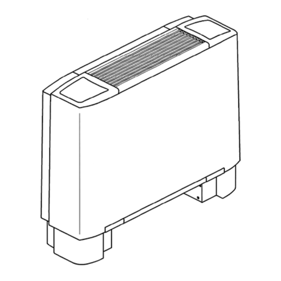
Assembly and operating instructions General Instructions Replaceable synthetic filter. Read these instructions carefully before Condensation box made of plastic. L-profile installation and use. Keep this manual for securely mounted in the fan convector. future reference. The product may only be used as set out in Mounting (Fig.1 p.3) the assembly and operating instructions. -
Page 30: Water Connections
Mounting of built-in control panels (Fig.2 • During the summer and when the fan is not used for long periods, it is recommended – that the water supply to the convector is Built-in control panels must be mounted on the disconnected to prevent condensation on the opposite side from the fan convector's water outside of the unit. - Page 31 Connection Cleaning, maintenance and spare parts General Instructions Important! • Perform electrical connections according to applicable laws and regulations for the • Ensure that the unit is disconnected from the power supply before cleaning or relevant country. maintenance. • Install an isolator switch upstream, with a minimum break gap of 3 mm.
-
Page 32: Safety Regulations
Safety regulations Safety • Check that the unit is earth protected. • Never insert foreign objects through the air intake or exhaust grilles. • Do not lift units more than 30 kg on your own, ask for the help of another person. •... -
Page 33: Installation Instructions
PCW-PCR1 Regulation Accessories With PCR1, only one fan convector can be controlled. If more than one fan convector is PCR1 to be controlled by the same control panel, external regulation PCEC/PCEA is used. Each Technical specification unit must be equipped with a PCPU. (E.g.: 2 x •... -
Page 34: Technical Specification
PCW-PCR2 PCR2 Configuration switches The configuration switches (DIP switches) Technical specification are used to set which function you want for • Supply voltage: 230V, 50Hz regulating the fan convector. • Setting range: +15–30 °C • Connection temperature difference: 0.7K Configuration switch The fan convector is connected to 230V even if the thermostat is off. - Page 35 PCW-PCR2 Possibility of external control (230V~signals) Night reduction / setpoint offset IN1: Night reduction / setpoint offset via Obtained by setting DIP-3 to "ON" and giving a external timer or external on/off. 230 V~ signal via an external timer or a switch IN2: External change between winter and to IN1.
- Page 36 PCW-PCR2 Winter/summer operation There are different options for changing between winter and summer operation. 2-pipe installations • Manual changing between sun (winter) and snowflake (summer) operation on the panel. Jumper position (1–2). • External changing via 230 V AC -signal on input IN2 from a dominant system or heat pump (change-over).
- Page 37 • A sensor connected to T3 can be used to limit the water temperature between 38 °C and 34 °C (applies to heating operation) or to limit the water temperature between 21 °C and 24 °C (applies to cooling operation). Please contact Frico for more information.
- Page 38 PCW-PCEB Configuration switches Make sure the control panel is disconnected from the power supply before setting the configuration switches (DIP switches). * = Default settings x = Not important for the specific function Configuration Switch position T3 winter and summer (only 2-pipe systems) T3 only winter (2- and 4-pipe systems) OFF* Continuous ventilation...
- Page 39 PCW-PCEC PCEC Accessories Technical specification With PCEC, up to ten fan coils can be controlled. • Manual or automatic regulation of the fan in Each unit must then be equipped with a PCPU. three steps. (E.g.: 2 x PCW, 2 x PCPU and 1 x PCEC/PCEA.). •...
-
Page 40: Main Board
PCW-PCEA PCEA Technical specification Accessories With PCEA, up to ten fan coils can be controlled. • Manual or automatic regulation of the fan in Each unit must then be equipped with a PCPU. three steps. (E.g.: 2 x PCW, 2 x PCPU and 1 x PCEC/PCEA.). •... - Page 41 PCW-PCPU PCPU Electronic board: Technical specification D1 = Configuration dip switches • Power unit for PCEC/PCEA. With PCEC/PCEA, D2 = Speed of dip switches up to ten fan coils can be controlled. Each J1 = Jumper MC3 unit must then be equipped with a PCPU. T1 = Air probe (mounted at the inlet of the unit) (E.g.: 2 x PCW, 2 x PCPU and 1 x PCEC/PCEA.).
-
Page 42: Configuration Switches
PCW-PCPU Configuration switches Default Position 4-pipe system 2-pipe system Thermal power station with fan Thermal power station with valves Simultaneous ventilation of valves Continuous ventilation T3 winter and summer T3 only winter ECM Motor Asynchronous Motor Button IAQ/Resistance ENABLED Button IAQ/Resistance DISABLED Resistance-coils management Resistance-coils with T2 T2 as CH Change-over (resistance phase... - Page 43 PCW-PCPU Mounting of PCPU in PCW...
-
Page 44: Installation Remarks
PCW-PCPU Operation of main and secondary units Managing units with serial connection. It is possible to connect and control several units simultaneously by transferring the settings from the control panel to a main unit. The other units are called secondary units. However, the operation of each unit depends on its temperature condition. - Page 48 Main offi ce Frico AB Tel: +46 31 336 86 00 Industrivägen 41 SE-433 61 Sävedalen mailbox@frico.se Sweden www.frico.net For latest updated information and information about your local contact: www.frico.net...
Need help?
Do you have a question about the PCW Series and is the answer not in the manual?
Questions and answers