Advertisement
Quick Links
Advertisement

Related Manuals for Frico PCW Series


Summary of Contents for Frico PCW Series
- Page 1 Original instructions SE ... 32 NO ... 48 GB ... 64 FR ... 80...
- Page 2 160,5 160,5 [mm] [mm] [mm] [mm] PCW132S/134S PCW232S/234S PCW332S/334S 1205 1205 PCW432S/434S PCW532S/534S 1420 1099...
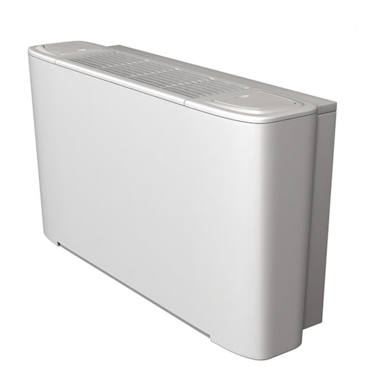
- Page 3 Montering / Mounting / Montering / Montage Fig.1...
- Page 4 Montering av inbyggd kontrollenhet / Mounting of build-in controls / Montering av innebygde kontrollenheter / Montage des régulateurs intégrés Fig.2: A-C...
- Page 5 Fig.2: D-G...
- Page 6 Dimensioneringstabeller, 3-radigt batteri, 2-rörsystem, värme Output charts water, 3 row coil, 2-pipe system, heating Effektdiagrammer, vann, 3-raders batteri, 2-rørssystem, varme Tableaux de rendement eau, batterie à 3 rangées, système à 2 tuyaux, chauffage. Incoming air temperature 20 °C Water temperature Water temperature Water temperature 60/40 °C...
- Page 7 Dimensioneringstabeller, 3-radigt batteri, 2-rörsystem, kyla. Luftfuktigh.: 50% Output charts water, 3 row coil, 2-pipe system, cooling. R.H. 50% Effektdiagrammer, vann, 3-raders batteri, 2-rørssystem, kjøling. Relativ fuktighet: 50 % Tableaux de rendement eau, batterie à 3 rangées, système à 2 tuyaux, refroidissement.
- Page 8 Dimensioneringstabeller, 3-rad. batteri-kyla, 1-rad. batteri-värme, 4-rörsystem Output charts water, 3 row coil-cooling, 1 row coil-heating, 4-pipe system Effektdiagrammer, vann, 3-raders batteri-kjøling, 1-rads batteri-varme, 4-rørssystem Tableaux de rendement eau, batterie à 3 rangées, batterie à 1 rangée pour chauffage, système à 4 tuyaux. Incoming air temperature 24 °C Incoming air temperature 20 °C Water temperature 7/12 °C...
- Page 9 Tryckfallsdiagram över fläktkonvektor PCW / Water pressure drop over PCW water coil / Trykkfall over vannbatteri PCW / Perte de charge PCW chauffage à eau chaude 3-radigt batteri / 3 row coil / 3-raders batteri Tryckförlusten i diagrammet är beräknad / batterie à...
- Page 10 Vattenregleringar / Water controls / Vannregulering / Régulateurs hydrauliques PCVR13C /PCVR45 PCVR13C: PCW132S, PCW232S, PCW332S PCVR45: PCW432S, PCW532S ± 10 mm PCVR315 PCVR315: PCW134S, PCW234S, PCW334S, PCW434S, PCW534S ± 10 mm Dimensions Valve Micrometric lockshield valve Ø Ø PCVR13C 1/2"F 1/2"F 1/2"F PCVR45...
- Page 11 PCVR213 /PCVR245 PCVR213: PCW132/134S, PCW232/234S, PCW332/334S PCVR245: PCW432/434S, PCW532/534S ± 10 mm Dimensions Valve Main coil Additional coil Main coil Additional coil Ø Ø PCVR213 1/2"F 1/2" 3/4"F 1/2" PCVR245 Ordlista Vattenregleringar Glossary Water controls Ordliste Vannregulering Glossaire des régulateurs hydrauliques Mått / Dimensions / Mål/ Dimensions Ventil / Valve / Ventil / Vanne Manuell avstängningsventil / Micrometric lockshield valve / Mikrometrisk avstengningsventil...
- Page 12 Tryckfallsdiagram över ventiler / Pressure drop over valves / Trykkfallsdiagram over ventiler / Vannes de perte de charge hydraulique PCVR13C / PCVR45 Kvs 2 Kvs 2,5 Kvs 1,6 300 400 600 800 1000 2000 3000 4000 PCVR213 / PCVR245 Kvs 1,7 Kvs 2,8 300 400 600 800 1000...
- Page 13 Tillbehör / Accessories / Tilbehør / Accessoires PCTV PCSHL / PCSHR PCSHL PCSHR L [mm] PCW132/134S 430 PCW232/234S 645 PCG332/334S PCG532/534S 1119...
- Page 14 PCG1: PCW132S / PCW134S PCG2: PCW223S / PCW234S PCG34: PCW332/432S / PCW334/434S PCW532S / PCW534S PCG5: PCG1 455x100x30 PCG2 670x100x30 PCG34 885x100x30 1100x100x30 PCG5...
- Page 15 Regleringar / Controls / Reguleringer / Régulateurs PCR1 PCR2 PCAS PCER1 PCER2...
- Page 16 PCR1 Utan ventil / Without valve / Uten ventil / Sans vanne Temperature sensor Light blue With low cut-out thermostat 230V 50Hz 3 speed 230V 50Hz *Obs! Bygel *Note! Bridge *NB! Klemme *NB! Shunt...
- Page 17 Med 1 ventil With 1 valve Med 1 ventil Avec 1 vanne Temperature sensor Light blue *Obs! Bygel *Note! Bridge *NB! Klemme With low cut-out thermostat *NB! Shunt 230V 50Hz 3 speed 230V 50Hz Med 2 ventiler With 2 valves Med 2 ventiler Avec 2 vannes Temperature...
- Page 18 PCER1 Utan ventil / Without valve / Uten ventil / Sans vanne PCER1 L (230V) 230V 50Hz 230V 50Hz 3 speed...
- Page 19 Med 1 ventil With 1 valve PCER1 Med 1 ventil L (230V) Avec 1 vanne 230V 50Hz 230V 50Hz 3 speed Med 2 ventiler With 2 valves Med 2 ventiler Avec 2 vannes PCER1 L (230V) 230V 50Hz Blue 230V 50Hz 3 speed...
- Page 20 PCR2 Utan ventil / Without valve / Uten ventil / Sans vanne 5 4 3 2 1 6 5 4 3 2 1 Temperature sensor Light blue (Low cut-out thermostat) External control 230V 50Hz 3 speed Summer 230V 50Hz CH=IN2 L (230VAC) Winter IN1: Set point reduction...
- Page 21 Med 1 ventil 5 4 3 2 1 6 5 4 3 2 1 With 1 valve Med 1 ventil Avec 1 vanne Temperature sensor Light blue (Low cut-out thermostat) *Obs! Bygel *Note! Bridge *NB! Klemme *NB! Shunt External control 230V 50Hz 3 speed Summer...
- Page 22 PCER2 Utan ventil / Without valve / Uten ventil / Sans vanne L (230V) PCER2 230V 50Hz 230V 50Hz 3 speed...
- Page 23 Med 1 ventil With 1 valve Med 1 ventil Avec 1 vanne L (230V) PCER2 230V 50Hz 230V 50Hz 3 speed Med 2 ventiler With 2 valves Med 2 ventiler Avec 2 vannes L (230V) PCER2 230V 50Hz Blue 230V 50Hz 3 speed...
- Page 24 PCAS Blue Brown Orange Blue Black 10 11 12 SPEED SELECTOR 1 2 3 4 5 20 21 22 Brown Brown Brown...
- Page 25 PCAS + PCER1 Utan ventil / Without valve / Uten ventil / Sans vanne...
- Page 26 Med 1 ventil With 1 valve Med 1 ventil Avec 1 vanne...
- Page 27 Med 2 ventiler With 2 valves Med 2 ventiler Avec 2 vannes...
- Page 28 PCAS + PCER2 Utan ventil / Without valve / Uten ventil / Sans vanne...
- Page 29 Med 1 ventil With 1 valve Med 1 ventil Avec 1 vanne...
- Page 30 Med 2 ventiler With 2 valves Med 2 ventiler Avec 2 vannes...
- Page 31 Ordlista kopplingsscheman Glossary wiring diagrams Ordliste Koblingsskjema Glossaire des schémas de raccordement Ljusblå / Light blue / Lyseblå / Bleu clair Blå / Blue / Blå / Bleu Brun / Brown / Brun / Brun Röd / Red / Rød / Rouge Orange / Orange / Oransje / Orange Svart / Black / Svart / Noir Gul / Yellow / Gul / Jaune...
-
Page 32: Technical Specification
Technical specification Type Air- Heating Cooling Cooling Sound Motor Amperage Water Weight flow output output level output volume output total sensitive [dB(A)] [lit] [kg] [kW] [kW] [kW] 2 pipe system PCW132S 2,02 1,56 1,24 0,18 PCW232S 2,92 2,39 1,80 0,23 PCW332S 4,50 3,64... -
Page 33: Water Coil
Water coil Max. water temperature in: +85 °C Min. water temperature in: +5 °C Max. working temperature: 1000 kPA (10 bar) Dimensions 3 row coil, 2 pipe system 3 row + 1 row coil, 4 pipe system Ø 1/2" F Ø... - Page 34 Assembly and operating instructions General Instructions The connections are located to the left as standard, seen from the front. The units can Read these instructions carefully before be supplied with the connection on the right- installation and use. Keep this manual for hand side if required.
- Page 35 Mounting of built-in control units (Fig.2 condensation on the outside of the unit. p.4-5) • If a supplementary condensation box is used it must be attached to frame's Built-in control units must be mounted on the connection side and the condensation pipe opposite side from the fan convector's water must be attached to the condensation box.
- Page 36 Cleaning, maintenance and spare parts Connection General Instructions Important! • Perform electrical connections according Ensure that the unit is disconnected from to applicable laws and regulations for the the power supply before starting cleaning or relevant country. maintenance. • Install an isolator switch upstream, with a minimum break gap of 3 mm.
- Page 37 Safety regulations Safety • Check that the unit is earth protected. • Never insert foreign objects through the air • Do not lift units more than 30 kg on your intake or exhaust grilles. own, ask for the help of another person. •...
- Page 38 Regulation Accessories With PCR1 only one fan convector can be controlled. If more than one fan convector PCR1 is to be controlled by the same control unit, Control panel for integration in the fan external regulation PCER1 is used. Each unit convector.
- Page 39 PCER1 Jumper This is used to select how the fan convector External control panel for wall mounting. is to change between winter and summer • Manual control of fan in 3 stages. operation. • Manual or automatic selection of heating or cooling.
- Page 40 Accessories If more than one fan convector is to be controlled by the same control unit, each fan convector must be supplied by a slave unit PCAS. (E.g.: 2. PCW, 2 x PCAS and 1 x. PCER1.) Limit thermostat PCT Secure the limit thermostat between the fins on the water coil.
- Page 41 PCR2 Configuration switch The configuration switches (DIP switches) Control panel for integration in the fan are used to set which function you want for convector. regulating the fan convector. • Manual or automatic selection of three fan speeds. • Manual or automatic selection of heating Configuration or cooling.
- Page 42 Possibility of external control Night reduction / setpoint offset (230V~signals) Obtained by setting DIP-3 to "ON" and giving IN1: Night reduction / setpoint offset via a 230 V~ signal via an external timer or a external timer or external on/off. switch to IN1.
- Page 43 Winter/summer operation See the wiring diagram. There are different options for changing between winter and summer operation. 2-pipe installations Manual changing between sun (winter) and snowflake (summer) operation on the panel. Jumper position (1-2) External changing via 230 V AC -signal on input IN2 from a dominant system or heat pump (CHANGEOVER).
- Page 44 PCER2 Configuration switch The configuration switches (DIP switches) External control panel for wall mounting. are used to set which function you want for • Manual or automatic selection of 3 fan regulating the fan convector. speeds. • Manual or automatic selection of heating or cooling.
- Page 45 Jumper Accessories Jumper used to select how the fan convector If more than one fan convector is to be is to change between winter and summer controlled by the same control unit, each fan operation. convector must be supplied by a slave unit PCAS.
- Page 46 Kyla Värme 1´ 2´ 3´ 4´ 5´ 6´ 0,7°C 0,7°C 0,7°C 0,7°C 0,7°C 0,7°C 1°C 1°C Temperatur Neutral zon Function diagram with neutral zone Position 3 = Hot water valve OFF Position 3' = Cold water valve OFF Position 4 = Hot water valve ON Position 4' = Cold water valve ON Speed:...
- Page 47 PCAS When controlling more than one fan convector PCW, the PCAS slave unit must be used together with PCER1 or PCER2. Each fan unit is supplied with its own PCAS and then controlled by a PCER1 or PCER2. A maximum of 8 fan convectors can be controlled across a control unit.
- Page 48 Main offi ce Frico AB Tel: +46 31 336 86 00 Industrivägen 41 SE-433 61 Sävedalen mailbox@frico.se Sweden www.frico.net For latest updated information and information about your local contact: www.frico.net.
Need help?
Do you have a question about the PCW Series and is the answer not in the manual?
Questions and answers