Table of Contents
Advertisement
Quick Links
TPS2553Q1EVM (HVL125A) Precision Current Limiting
The Texas Instruments TPS2553Q1EVM evaluation module (EVM) helps designers evaluate the operation
and performance of the TPS2553-Q1. This user's guide describes the TPS2553Q1EVM evaluation module
(EVM). This guide contains the EVM schematic, bill of materials (BoM), assembly drawing, and top and
bottom board layouts.
...................................................................................................................
1
2
3
1
2
3
4
5
6
7
.....................................................................................................................
8
9
10
11
12
13
14
15
16
17
Test Setup for Auto-Retry Functionality
18
..........................................................................................................................
1
2
3
4
5
All trademarks are the property of their respective owners.
SLVUAT7 - October 2016
Submit Documentation Feedback
.................................................................................
.......................................................................................................
....................................................................................................
...............................................................................................
....................................................................................................
..................................................................................................................
................................................................................................
.................................................................................................................
...............................................................................................................
...............................................................................................................
..................................................................................
..................................................................................
.................................................................................
.................................................................................
.....................................................................................................
...................................................................................
.................................................................................................
............................................................................................
TPS2553Q1EVM (HVL125A) Precision Current Limiting Switch User Guide
Copyright © 2016, Texas Instruments Incorporated
Contents
List of Figures
....................................................................
................................................................
...............................................................................
......................................................................
.......................................................................
List of Tables
User's Guide
SLVUAT7 - October 2016
Switch User Guide
2
3
9
2
3
5
5
6
6
7
7
8
11
11
11
13
13
13
15
15
15
3
9
9
10
10
1
Advertisement
Table of Contents

Subscribe to Our Youtube Channel
Related Manuals for Texas Instruments TPS2553Q1EVM


Summary of Contents for Texas Instruments TPS2553Q1EVM
-
Page 1: Table Of Contents
The Texas Instruments TPS2553Q1EVM evaluation module (EVM) helps designers evaluate the operation and performance of the TPS2553-Q1. This user’s guide describes the TPS2553Q1EVM evaluation module (EVM). This guide contains the EVM schematic, bill of materials (BoM), assembly drawing, and top and bottom board layouts. -
Page 2: Introduction
Introduction The TPS2553Q1EVM is an evaluation module (EVM) for an automotive power-distribution switch with adjustable current-limiting outputs provided by Texas Instruments. The EVM has an operating voltage range of around 2.5 V to 6.5 V, and has four different output current limits, based on jumper placement on the board. -
Page 3: Schematic, Bill Of Materials, And Layout
Schematic, Bill of Materials, and Layout www.ti.com Schematic, Bill of Materials, and Layout This section provides a detailed description of the TPS2553Q1EVM schematic, bill of materials (BOM), and layout. Schematic VIN = 2.5 V – 6.5 V VIN(Max) = 7 V 10 µF... - Page 4 DBV0006A TPS2553QDBVRQ1 Texas Instruments SWITCHES, DBV0006A Fiducial mark. There is nothing to buy or FID1, FID2, FID3 Fiducial mount. TPS2553Q1EVM (HVL125A) Precision Current Limiting Switch User Guide SLVUAT7 – October 2016 Submit Documentation Feedback Copyright © 2016, Texas Instruments Incorporated...
-
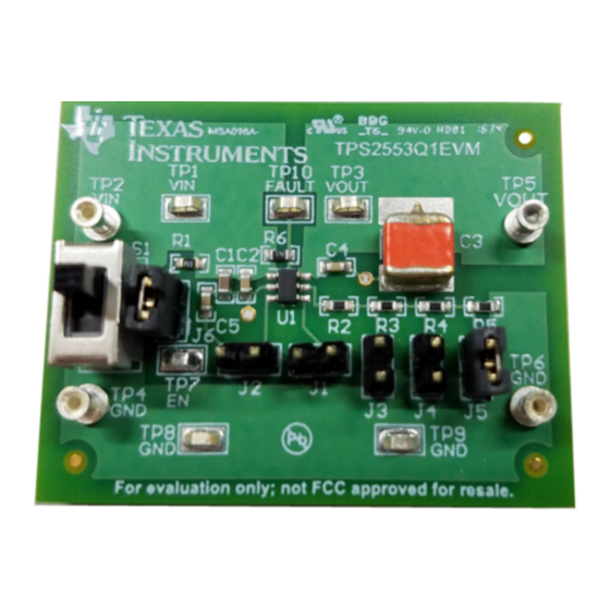
Page 5: Evm Board Image For Tps2553Q1Evm (Top View)
Figure 4 top and bottom overviews of the printed circuit board (PCB) show the component placement of the EVM. Figure 3. EVM Board Image for TPS2553Q1EVM (Top View) Figure 4. EVM Board Image for TPS2553Q1EVM (Bottom View) SLVUAT7 – October 2016... -
Page 6: Layout-Top Composite
Schematic, Bill of Materials, and Layout www.ti.com Figure 5. Layout—Top Composite Figure 6. Top Overlay TPS2553Q1EVM (HVL125A) Precision Current Limiting Switch User Guide SLVUAT7 – October 2016 Submit Documentation Feedback Copyright © 2016, Texas Instruments Incorporated... -
Page 7: Layout-Bottom Composite
Schematic, Bill of Materials, and Layout www.ti.com Figure 7. Layout—Bottom Composite Figure 8. Top Layer SLVUAT7 – October 2016 TPS2553Q1EVM (HVL125A) Precision Current Limiting Switch User Guide Submit Documentation Feedback Copyright © 2016, Texas Instruments Incorporated... -
Page 8: Bottom Layer
Schematic, Bill of Materials, and Layout www.ti.com Figure 9. Bottom Layer TPS2553Q1EVM (HVL125A) Precision Current Limiting Switch User Guide SLVUAT7 – October 2016 Submit Documentation Feedback Copyright © 2016, Texas Instruments Incorporated... -
Page 9: Setup And Operation
Fault signal voltage monitoring Jumper Settings and Configuration The jumpers onboard the TPS2553Q1EVM may be put into two functional categories. The first set of jumpers may either manually set the enable signal to a logic high or low, or utilize the auto-retry functionality of the device. -
Page 10: Current Limiting Jumpers
It is recommended to use at least a 5-W power resistor in this setup, because of the high current output. TPS2553Q1EVM (HVL125A) Precision Current Limiting Switch User Guide SLVUAT7 – October 2016 Submit Documentation Feedback... -
Page 11: Test Setup For Turnon And Turnoff Delay
5-ohm load. Returning the enable switch to its original position achieves turnoff. SLVUAT7 – October 2016 TPS2553Q1EVM (HVL125A) Precision Current Limiting Switch User Guide Submit Documentation Feedback Copyright © 2016, Texas Instruments Incorporated... - Page 12 Changing the R jumpers in this setup allows the user to adjust the output ILIM short-circuit current. TPS2553Q1EVM (HVL125A) Precision Current Limiting Switch User Guide SLVUAT7 – October 2016 Submit Documentation Feedback Copyright © 2016, Texas Instruments Incorporated...
-
Page 13: Test Setup For Short-Circuit Output Current-Limit
5-ohm load is reapplied. The device exits the thermal cycling stage and returns to a current of around 1 A. SLVUAT7 – October 2016 TPS2553Q1EVM (HVL125A) Precision Current Limiting Switch User Guide Submit Documentation Feedback Copyright © 2016, Texas Instruments Incorporated... - Page 14 The J1 and J2 jumpers are shown in Figure 16 for clarity. Note that the device must be constantly shorted for auto-retry operation to be viewed. TPS2553Q1EVM (HVL125A) Precision Current Limiting Switch User Guide SLVUAT7 – October 2016 Submit Documentation Feedback Copyright © 2016, Texas Instruments Incorporated...
-
Page 15: Test Setup For Auto-Retry Functionality
Figure 18 shows the device in auto-retry mode with J3 asserted on the TPS2553Q1EVM. The retry time is around 3.7 ms for this setup. Note that the device Figure 18 is in auto-retry mode, as well as performing thermal cycling because of the overcurrent level present. - Page 16 Figure 18. Test Setup for Auto-Retry Functionality With J3 Figure 17. Test Setup for Auto-Retry Functionality Revision History DATE REVISION NOTES October 2016 Initial release Revision History SLVUAT7 – October 2016 Submit Documentation Feedback Copyright © 2016, Texas Instruments Incorporated...
- Page 17 STANDARD TERMS AND CONDITIONS FOR EVALUATION MODULES Delivery: TI delivers TI evaluation boards, kits, or modules, including demonstration software, components, and/or documentation which may be provided together or separately (collectively, an “EVM” or “EVMs”) to the User (“User”) in accordance with the terms and conditions set forth herein.
- Page 18 FCC Interference Statement for Class B EVM devices NOTE: This equipment has been tested and found to comply with the limits for a Class B digital device, pursuant to part 15 of the FCC Rules. These limits are designed to provide reasonable protection against harmful interference in a residential installation.
- Page 19 【無線電波を送信する製品の開発キットをお使いになる際の注意事項】 開発キットの中には技術基準適合証明を受けて いないものがあります。 技術適合証明を受けていないもののご使用に際しては、電波法遵守のため、以下のいずれかの 措置を取っていただく必要がありますのでご注意ください。 1. 電波法施行規則第6条第1項第1号に基づく平成18年3月28日総務省告示第173号で定められた電波暗室等の試験設備でご使用 いただく。 2. 実験局の免許を取得後ご使用いただく。 3. 技術基準適合証明を取得後ご使用いただく。 なお、本製品は、上記の「ご使用にあたっての注意」を譲渡先、移転先に通知しない限り、譲渡、移転できないものとします。 上記を遵守頂けない場合は、電波法の罰則が適用される可能性があることをご留意ください。 日本テキサス・イ ンスツルメンツ株式会社 東京都新宿区西新宿6丁目24番1号 西新宿三井ビル 3.3.3 Notice for EVMs for Power Line Communication: Please see http://www.tij.co.jp/lsds/ti_ja/general/eStore/notice_02.page 電力線搬送波通信についての開発キットをお使いになる際の注意事項については、次のところをご覧ください。http:/ /www.tij.co.jp/lsds/ti_ja/general/eStore/notice_02.page SPACER EVM Use Restrictions and Warnings: 4.1 EVMS ARE NOT FOR USE IN FUNCTIONAL SAFETY AND/OR SAFETY CRITICAL EVALUATIONS, INCLUDING BUT NOT LIMITED TO EVALUATIONS OF LIFE SUPPORT APPLICATIONS.
- Page 20 Notwithstanding the foregoing, any judgment may be enforced in any United States or foreign court, and TI may seek injunctive relief in any United States or foreign court. Mailing Address: Texas Instruments, Post Office Box 655303, Dallas, Texas 75265 Copyright © 2016, Texas Instruments Incorporated...
- Page 21 IMPORTANT NOTICE Texas Instruments Incorporated and its subsidiaries (TI) reserve the right to make corrections, enhancements, improvements and other changes to its semiconductor products and services per JESD46, latest issue, and to discontinue any product or service per JESD48, latest issue.
- Page 22 Mouser Electronics Authorized Distributor Click to View Pricing, Inventory, Delivery & Lifecycle Information: Texas Instruments TPS2553Q1EVM...
Need help?
Do you have a question about the TPS2553Q1EVM and is the answer not in the manual?
Questions and answers