Advertisement
Quick Links
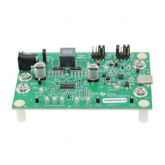
TPS25740EVM-741 and TPS25740AEVM-741 Evaluation
This user's guide describes the TPS25740 and TPS25740A evaluation module (TPS25740EVM-741 and
TPS25740AEVM-741). The TPS25740EVM-741 and TPS25740AEVM-741 contain evaluation and
reference circuitry for the TPS25740 and TPS25740A, which are dedicated USB Type-C™ Power Delivery
(PD) downstream facing port (DFP) controllers. The TPS25740 and TPS25740A rely on an upstream
converter to output 5 V, 12 V, and 20 V (TPS25740) or 5 V, 9 V, and 15 V (TPS25740A). These EVMs
use an LM5175-based buck boost converter as the power supply for TPS25740 and TPS25740A. The
TPS25740 and TPS25740A portion of the circuit will be very similar in an adapter application where an
AC/DC input power stage is used. Note that this EVM does not support BC1.2 charging. A TPS2514A can
be added to DP and DM lines of the type C connector for BC1.2 charging support. In addition this EVM
features a barrel jack input to allow for easy demonstration. The recommended adapter is listed in the
features section.
...................................................................................................................
1
Introduction
....................................................................................................................
2
Description
.....................................................................................................................
3
Schematic
4
Configuring the EVM
.....................................................................................................................
5
Operation
6
Test Results
7
EVM Assembly Drawings and Layout Guidelines
8
Component Placement and Routing Guidelines
9
Bill of Materials
1
Block Diagram
2
LM5175 Buck-Boost Power Supply
3
TPS25740 DFP
4
Power Select Header – J7
5
Voltage and Current Select Header – J8
6
UFP Plug-In (5 V)
7
UFP Unplug (5 V)
8
UFP Unplug (12 V)
9
UFP Unplug (20 V)
10
5-V to 12-V Transition
11
5-V to 20-V Transition
12
12-V to 20-V Transition
13
12-V to 5-V Transition
14
20-V to 5-V Transition
15
20-V to 12-V Transition
16
Start Into Short on Output
17
Start Into Short on Output (Extra 1000 µF Between DCDC_out and GND)
18
Load Step From 0 A to 3 A (12 V)
USB Type-C is a trademark of USB Implementers Forum, Inc.
SLVUAP7A – April 2016 – Revised September 2016
Submit Documentation Feedback
........................................................................................................
..................................................................................................................
.............................................................................................................
................................................................................................................
.......................................................................................
..............................................................................................................
.................................................................................................
.................................................................................
............................................................................................................
............................................................................................................
..........................................................................................................
..........................................................................................................
.......................................................................................................
.......................................................................................................
....................................................................................................
.....................................................................................................
.....................................................................................................
....................................................................................................
.................................................................................................
.......................................................................................
TPS25740EVM-741 and TPS25740AEVM-741 Evaluation Module User
Copyright © 2016, Texas Instruments Incorporated
SLVUAP7A – April 2016 – Revised September 2016
Module User Guide
Contents
......................................................................
.......................................................................
List of Figures
User's Guide
........................................
Guide
3
4
5
7
9
9
15
18
19
3
5
6
8
8
9
9
9
9
9
9
10
10
10
10
10
10
11
1
Advertisement

Related Manuals for Texas Instruments TPS25740EVM-741


Summary of Contents for Texas Instruments TPS25740EVM-741
- Page 1 TPS25740EVM-741 and TPS25740AEVM-741 Evaluation Module User Guide This user’s guide describes the TPS25740 and TPS25740A evaluation module (TPS25740EVM-741 and TPS25740AEVM-741). The TPS25740EVM-741 and TPS25740AEVM-741 contain evaluation and reference circuitry for the TPS25740 and TPS25740A, which are dedicated USB Type-C™ Power Delivery (PD) downstream facing port (DFP) controllers.
- Page 2 ..................Connector and LED Functionality ....................... Jumpers Functionality ........................Test Points ..................TPS25740EVM-741 Bill of Materials TPS25740EVM-741 and TPS25740AEVM-741 Evaluation Module User SLVUAP7A – April 2016 – Revised September 2016 Guide Submit Documentation Feedback Copyright © 2016, Texas Instruments Incorporated...
- Page 3 Introduction The TPS25740EVM-741 and TPS25740AEVM-741 allows the user to evaluate performance of the TPS25740 and TPS25740A in an adapter-like application. Note that the TPS25740 and TPS25740A are powered from the output of the DC/DC converter and do not require an external LDO. The upstream converter remains ON at all times to ensure that the TPS25740 and TPS25740A remain powered and can detect the UFP connection.
- Page 4 Capacitors C31 and C32 provide slew rate control in order to comply with the USB PD specification. For more information and detailed design information, refer to the TPS25740/TPS25740A datasheet, (SLVSDG8). TPS25740EVM-741 and TPS25740AEVM-741 Evaluation Module User SLVUAP7A – April 2016 – Revised September 2016 Guide Submit Documentation Feedback...
- Page 5 1µF 1µF 0.1µF 9.53k Copyright © 2016, Texas Instruments Incorporated Figure 2. LM5175 Buck-Boost Power Supply SLVUAP7A – April 2016 – Revised September 2016 TPS25740EVM-741 and TPS25740AEVM-741 Evaluation Module User Guide Submit Documentation Feedback Copyright © 2016, Texas Instruments Incorporated...
- Page 6 100k VAUX 100k HDVDD PSEL HIPWR Copyright © 2016, Texas Instruments Incorporated Figure 3. TPS25740 DFP TPS25740EVM-741 and TPS25740AEVM-741 Evaluation Module User Guide SLVUAP7A – April 2016 – Revised September 2016 Submit Documentation Feedback Copyright © 2016, Texas Instruments Incorporated...
- Page 7 Configuring the EVM www.ti.com Configuring the EVM Physical Access Table 2 lists the TPS25740EVM-741 connector and LED functionality, Table 3 describes jumper functionality, and Table 4 describes the test point availability. Table 2. Connector and LED Functionality Connector Label Description Power bus input.
- Page 8 • PD capable UFP to negotiate voltages, in this case the TPS25720 EVM was used • Type C cable TPS25740EVM-741 and TPS25740AEVM-741 Evaluation Module User SLVUAP7A – April 2016 – Revised September 2016 Guide Submit Documentation Feedback Copyright © 2016, Texas Instruments Incorporated...
- Page 9 4. Connect load between J2 and J5 as desired to test efficiency and other performance. Test Results This section provides typical performance waveforms for the TPS25740EVM-741 and TPS25740AEVM- 741 with VIN = 12 V at no load (unless otherwise specified). Actual performance data is affected by measurement techniques and environmental variables;...
- Page 10 Figure 12. 12-V to 20-V Transition Figure 13. 12-V to 5-V Transition Figure 14. 20-V to 5-V Transition Figure 15. 20-V to 12-V Transition TPS25740EVM-741 and TPS25740AEVM-741 Evaluation Module User SLVUAP7A – April 2016 – Revised September 2016 Guide Submit Documentation Feedback...
- Page 11 Figure 20. Load Step From 0 A to 3 A (5 V) Figure 21. Raise V With UFP Already Plugged In SLVUAP7A – April 2016 – Revised September 2016 TPS25740EVM-741 and TPS25740AEVM-741 Evaluation Module User Guide Submit Documentation Feedback Copyright © 2016, Texas Instruments Incorporated...
- Page 12 Figure 26. Overvoltage at 12-V Contract (With External Figure 27. Overvoltage at 20-V Contract (With External Supply) Supply) TPS25740EVM-741 and TPS25740AEVM-741 Evaluation Module User SLVUAP7A – April 2016 – Revised September 2016 Guide Submit Documentation Feedback Copyright © 2016, Texas Instruments Incorporated...
- Page 13 Figure 32. 5.5-A Load Step Triggers OCP (20 V) Figure 33. Plug In to MacBook (5-V, 12-V, 20-V Advertised) SLVUAP7A – April 2016 – Revised September 2016 TPS25740EVM-741 and TPS25740AEVM-741 Evaluation Module User Guide Submit Documentation Feedback Copyright © 2016, Texas Instruments Incorporated...
- Page 14 Figure 36. Unplug MacBook (5-V and 12-V Advertised) Figure 37. Power Cycle MacBook Plugged In (5-V, 12-V, 20-V Advertised) Figure 38. Power Cycle With MacBook (5-V and 12-V Advertised) TPS25740EVM-741 and TPS25740AEVM-741 Evaluation Module User SLVUAP7A – April 2016 – Revised September 2016 Guide Submit Documentation Feedback...
- Page 15 Figure 43 show component placement and layout of the EVM. Figure 39. Top Side Placement SLVUAP7A – April 2016 – Revised September 2016 TPS25740EVM-741 and TPS25740AEVM-741 Evaluation Module User Guide Submit Documentation Feedback Copyright © 2016, Texas Instruments Incorporated...
- Page 16 EVM Assembly Drawings and Layout Guidelines www.ti.com Figure 40. Top Side Routing Figure 41. Layer Two Routing TPS25740EVM-741 and TPS25740AEVM-741 Evaluation Module User SLVUAP7A – April 2016 – Revised September 2016 Guide Submit Documentation Feedback Copyright © 2016, Texas Instruments Incorporated...
- Page 17 EVM Assembly Drawings and Layout Guidelines www.ti.com Figure 42. Layer Three Routing Figure 43. Bottom Side Routing SLVUAP7A – April 2016 – Revised September 2016 TPS25740EVM-741 and TPS25740AEVM-741 Evaluation Module User Guide Submit Documentation Feedback Copyright © 2016, Texas Instruments Incorporated...
- Page 18 • CVBUS/DVBUS: Place C23 and D4 within one inch of the Type C connector and connect them to VBUS and GND using adequate copper shapes. TPS25740EVM-741 and TPS25740AEVM-741 Evaluation Module User SLVUAP7A – April 2016 – Revised September 2016 Guide Submit Documentation Feedback Copyright ©...
- Page 19 Keystone Connector, DC Jack 2.1X5.5 mm, TH Conn, DC Jack, PJ-202AH CUI Inc. pin 2mm Dia. SLVUAP7A – April 2016 – Revised September 2016 TPS25740EVM-741 and TPS25740AEVM-741 Evaluation Module User Guide Submit Documentation Feedback Copyright © 2016, Texas Instruments Incorporated...
- Page 20 Bill of Materials www.ti.com Table 5. TPS25740EVM-741 Bill of Materials (continued) Designator Quantity Quantity Value Description Package Part Number Manufacturer Alternate Part Alternate (TPS25740) (TPS25740A) Reference Number Manufacturer Header, 100mil, 2x1, Gold with Tin Tail, SMT 2x1 Header TSM-102-01-L-SV Samtec J7, J8 Header, 2.54mm, 4x2, Gold, SMT...
- Page 21 Bill of Materials www.ti.com Table 5. TPS25740EVM-741 Bill of Materials (continued) Designator Quantity Quantity Value Description Package Part Number Manufacturer Alternate Part Alternate (TPS25740) (TPS25740A) Reference Number Manufacturer 24.9 RES, 24.9, 1%, 0.063 W, 0402 0402 CRCW040224R9FKED Vishay-Dale R47, R53 10.0...
- Page 22 Added and changed content in the Jumpers Functionality table......... • Changed Setting Advertisement Levels with J7 and J8 section. Removed red text references Revision History SLVUAP7A – April 2016 – Revised September 2016 Submit Documentation Feedback Copyright © 2016, Texas Instruments Incorporated...
- Page 23 STANDARD TERMS AND CONDITIONS FOR EVALUATION MODULES Delivery: TI delivers TI evaluation boards, kits, or modules, including any accompanying demonstration software, components, or documentation (collectively, an “EVM” or “EVMs”) to the User (“User”) in accordance with the terms and conditions set forth herein. Acceptance of the EVM is expressly subject to the following terms and conditions.
- Page 24 FCC Interference Statement for Class B EVM devices NOTE: This equipment has been tested and found to comply with the limits for a Class B digital device, pursuant to part 15 of the FCC Rules. These limits are designed to provide reasonable protection against harmful interference in a residential installation.
- Page 25 【無線電波を送信する製品の開発キットをお使いになる際の注意事項】 開発キットの中には技術基準適合証明を受けて いないものがあります。 技術適合証明を受けていないもののご使用に際しては、電波法遵守のため、以下のいずれかの 措置を取っていただく必要がありますのでご注意ください。 1. 電波法施行規則第6条第1項第1号に基づく平成18年3月28日総務省告示第173号で定められた電波暗室等の試験設備でご使用 いただく。 2. 実験局の免許を取得後ご使用いただく。 3. 技術基準適合証明を取得後ご使用いただく。 なお、本製品は、上記の「ご使用にあたっての注意」を譲渡先、移転先に通知しない限り、譲渡、移転できないものとします。 上記を遵守頂けない場合は、電波法の罰則が適用される可能性があることをご留意ください。 日本テキサス・イ ンスツルメンツ株式会社 東京都新宿区西新宿6丁目24番1号 西新宿三井ビル 3.3.3 Notice for EVMs for Power Line Communication: Please see http://www.tij.co.jp/lsds/ti_ja/general/eStore/notice_02.page 電力線搬送波通信についての開発キットをお使いになる際の注意事項については、次のところをご覧くださ い。http://www.tij.co.jp/lsds/ti_ja/general/eStore/notice_02.page SPACER EVM Use Restrictions and Warnings: 4.1 EVMS ARE NOT FOR USE IN FUNCTIONAL SAFETY AND/OR SAFETY CRITICAL EVALUATIONS, INCLUDING BUT NOT LIMITED TO EVALUATIONS OF LIFE SUPPORT APPLICATIONS.
- Page 26 Notwithstanding the foregoing, any judgment may be enforced in any United States or foreign court, and TI may seek injunctive relief in any United States or foreign court. Mailing Address: Texas Instruments, Post Office Box 655303, Dallas, Texas 75265 Copyright © 2015, Texas Instruments Incorporated...
- Page 27 STANDARD TERMS AND CONDITIONS FOR EVALUATION MODULES Delivery: TI delivers TI evaluation boards, kits, or modules, including demonstration software, components, and/or documentation which may be provided together or separately (collectively, an “EVM” or “EVMs”) to the User (“User”) in accordance with the terms and conditions set forth herein.
- Page 28 FCC Interference Statement for Class B EVM devices NOTE: This equipment has been tested and found to comply with the limits for a Class B digital device, pursuant to part 15 of the FCC Rules. These limits are designed to provide reasonable protection against harmful interference in a residential installation.
- Page 29 【無線電波を送信する製品の開発キットをお使いになる際の注意事項】 開発キットの中には技術基準適合証明を受けて いないものがあります。 技術適合証明を受けていないもののご使用に際しては、電波法遵守のため、以下のいずれかの 措置を取っていただく必要がありますのでご注意ください。 1. 電波法施行規則第6条第1項第1号に基づく平成18年3月28日総務省告示第173号で定められた電波暗室等の試験設備でご使用 いただく。 2. 実験局の免許を取得後ご使用いただく。 3. 技術基準適合証明を取得後ご使用いただく。 なお、本製品は、上記の「ご使用にあたっての注意」を譲渡先、移転先に通知しない限り、譲渡、移転できないものとします。 上記を遵守頂けない場合は、電波法の罰則が適用される可能性があることをご留意ください。 日本テキサス・イ ンスツルメンツ株式会社 東京都新宿区西新宿6丁目24番1号 西新宿三井ビル 3.3.3 Notice for EVMs for Power Line Communication: Please see http://www.tij.co.jp/lsds/ti_ja/general/eStore/notice_02.page 電力線搬送波通信についての開発キットをお使いになる際の注意事項については、次のところをご覧ください。http:/ /www.tij.co.jp/lsds/ti_ja/general/eStore/notice_02.page SPACER EVM Use Restrictions and Warnings: 4.1 EVMS ARE NOT FOR USE IN FUNCTIONAL SAFETY AND/OR SAFETY CRITICAL EVALUATIONS, INCLUDING BUT NOT LIMITED TO EVALUATIONS OF LIFE SUPPORT APPLICATIONS.
- Page 30 Notwithstanding the foregoing, any judgment may be enforced in any United States or foreign court, and TI may seek injunctive relief in any United States or foreign court. Mailing Address: Texas Instruments, Post Office Box 655303, Dallas, Texas 75265 Copyright © 2016, Texas Instruments Incorporated...
- Page 31 IMPORTANT NOTICE Texas Instruments Incorporated and its subsidiaries (TI) reserve the right to make corrections, enhancements, improvements and other changes to its semiconductor products and services per JESD46, latest issue, and to discontinue any product or service per JESD48, latest issue.
- Page 32 Mouser Electronics Authorized Distributor Click to View Pricing, Inventory, Delivery & Lifecycle Information: Texas Instruments TPS25740AEVM-741 TPS25740EVM-741...
Need help?
Do you have a question about the TPS25740EVM-741 and is the answer not in the manual?
Questions and answers