Table of Contents

Related Manuals for FS S3410C Series


Summary of Contents for FS S3410C Series
- Page 1 S3410C SERIES SMB SWITCHES SMB-SWITCHES DER SERIE S3410 SWITCH POUR PME DE LA SERIE S3410C S����CシリーズSMBスイッチ Quick Start Guide V1.0 Quick Start Anleitung Guide de Démarrage Rapide クイックスタートガイド...
- Page 2 Introduction Thank you for choosing the SMB Switches. This guide is designed to familiarize you with the layout of the switches and describes how to mount them in your network. S3410C-8TMS-P S3410C-16TMS-P S3410C-16TF S3410C-16TF-P...
-
Page 3: Hardware Overview
Accessories Power Cord x1 Grounding Cable x1 Mounting Bracket x2 M4 Screw x6 Mounting Bracket Installation Instruction x1 NOTE: The accessories may vary from illustration, please prevail in kind. NOTE: This power cord cannot be used with other devices, and other power cords should not be used with this device. - Page 4 S3410C-16TMS-P 1G/2.5G/5G Console SFP+ 10M/100M/1000M Ports Description Console An RJ45 console port for serial management RJ45 10M/100M/1000M/2.5G/5G Base-T ports for Ethernet connection SFP+ SFP+ ports for 1G/10G connection S3410C-16TF Console 10M/100M/1000M S3410C-16TF-P Console 10M/100M/1000M...
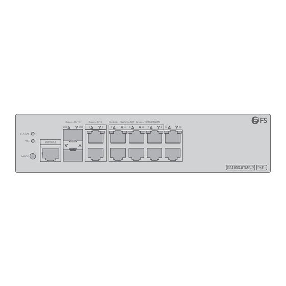
- Page 5 Ports Description Console An RJ45 console port for serial management RJ45 10M/100M/1000M Base-T ports for Ethernet connection SFP ports for 1G connection Front Panel LEDs S3410C-8TMS-P Status RJ45 (Switch Mode) SFP+ RJ45 (PoE Mode) S3410C-16TMS-P Status RJ45 (Switch Mode) RJ45 (PoE Mode) SFP+...
- Page 6 LEDs State Description The switch is not powered on. The switch is being initialized. Blinking Green Continuous blinking indicates a fault. Solid Green The switch is operating normally. Status A switch temperature alarm is Solid Yellow generated. The temperature severely exceeds Solid Red the threshold and the system restarts.
- Page 7 S3410C-16TF RJ45 Status S3410C-16TF-P Status RJ45 (Switch Mode) RJ45 (PoE Mode) LEDs State Description The switch is not powered on. The switch is being initialized. Continuous blinking Blinking Green indicates a fault. Status Solid Green The switch is operating normally. Solid Yellow A switch temperature alarm is generated.
- Page 8 LEDs State Description The port is not linked. The port is linked up at 10M/100M Solid Green RJ45 (for /1000M. 1~16 S3410C-16TF) The port is sending or receiving Blinking Green data at 10M/100M/1000M. The port is not linked. The port is linked up at 10M/100M Solid Green 1~16 /1000M.
-
Page 9: Front Panel Button
Front Panel Button S3410C-8TMS-P Mode S3410C-16TMS-P Mode S3410C-16TF-P Mode Button Description Mode Switch the display mode between PoE mode and switch mode. -
Page 10: Installation Requirements
Installation Requirements Before installation, make sure that you have the following conditions ready: Phillips screwdriver, slotted screwdriver, related bolts, diagonal pliers, cable ties, expansion screws, M6 screws, M6 cage nuts, ESD tools and multimeter. Standard-sized, 19" wide rack with a minimum of 1U height available. Category 5e or higher RJ45 Ethernet cables for connecting network devices. -
Page 11: Mounting The Switch
Mounting the Switch Rack Mounting 1. Install the mounting brackets to the switch with screws. 2. Attach the switch to the rack using M6 screws and cage nuts. NOTE: If there is a hot device around, the installation spacing should be greater than or equal to 2U. -
Page 12: Desk Mounting
Desk Mounting 1. Rotate the mounting brackets by 90 degrees, and secure the mounting brackets to the switch with the screws. 2. Secure the switch to the bottom of a desk with expansion screws. CAUTION: 1. The location where the device is mounted and operated must be subject to movement restrictions. - Page 13 Wall or Workbench Mounting 1. Drill holes on the wall based on the indication of the positioning paper, and install the mounting brackets. 2. Fasten the device to the mounting brackets. NOTE: 1. No obstacle is allowed within 90mm in front of the switch mounted on a wall.
- Page 14 Weak-Current Box Mounting ≥400mm >300mm ≥120mm NOTE: 1. No obstacle is allowed within 20cm in front of the front panel of the weak-current box, to prevent poor heat dissipation. 2. When installed in a weak-current box, the size of the weak-current box should be greater than 400mm x 300mm x 120mm, with the opening rate greater than 15%.
- Page 15 2. Place the device on the bracket and connect a network cable to a network port.
- Page 16 3. Connect the power cord to the device, con rm the power supply, close the door of the weak-current box, and lock it with the key. Method 2 Optional fastening position 2 1. The bracket is installed on the rst hole by default (the hole is 4mm away from the bottom).
- Page 17 2. Place the device on the bracket and connect a network cable to a network port.
-
Page 18: Grounding The Switch
3. Connect the power cord to the device, con rm the power supply, close the door of the weak-current box, and lock it with the key. Grounding the Switch 1. Connect one end of the grounding cable to a proper earth ground, such as the rack in which the switch is mounted. - Page 19 Connecting the RJ45 Ports 1. Connect one end of an Ethernet cable to the RJ45 port. 2. Connect the other end of the Ethernet cable to another network device. Connecting the SFP/SFP+ Ports 1. Plug the compatible SFP/SFP+ transceiver into the SFP/SFP+port. 2.
-
Page 20: Connecting The Console Port
Connecting the Console Port 1. Insert the RJ45 connector of the console cable into the console port of the switch. 2. Connect the DB9 female connector of the console cable to the serial port of the computer. Connecting the Power 1. -
Page 21: Troubleshooting
Troubleshooting The Power LED Is Working Abnormally 1. Check the power cable connections at the switch and the power source. 2. Make sure that all cables are used correctly and comply with the Ethernet speci cations. The RJ45 Port Is Disconnected or an Error Occurs in the Transmission and Receiving of Frames The connected twisted pair cable is faulty. -
Page 22: Product Warranty
Product Warranty FS ensures our customers that for any damage or faulty items due to our workmanship, we will o er a free return within 30 days from the day you receive your goods. We will also o er free software update service. This excludes any custom-made items or tailored solutions. - Page 23 Einführung Vielen Dank, dass Sie sich für SMB-Switches entschieden haben. Diese Anleitung soll Sie mit dem Aufbau der Switches vertraut machen und beschreibt, wie Sie diese in Ihrem Netzwerk montieren. S3410C-8TMS-P S3410C-16TMS-P S3410C-16TF S3410C-16TF-P...
- Page 24 Zubehör Netzkabel x1 Erdungskabel x1 Montagehalterung x2 M4-Schraube x6 Montageanleitung für die Montagehalterung x1 HINWEIS: Das Zubehör kann von der Abbildung abweichen, bitte beachten Sie die Art. HINWEIS: Dieses Netzkabel kann nicht mit anderen Geräten verwendet werden, und andere Netzkabel sollten nicht mit diesem Gerät verwendet werden. Hardware-Übersicht Panel an der Voderseite S3410C-8TMS-P...
- Page 25 S3410C-16TMS-P 1G/2.5G/5G Console SFP+ 10M/100M/1000M Ports Beschreibung Console Ein RJ45-Konsolenanschluss für die serielle Verwaltung RJ45 10M/100M/1000M/2,5G/5G Base-T-Ports für Ethernet-Verbindung SFP+ SFP+-Ports für 1G/10G-Verbindung S3410C-16TF Console 10M/100M/1000M S3410C-16TF-P Console 10M/100M/1000M...
- Page 26 Ports Beschreibung Console Ein RJ45-Konsolenanschluss für die serielle Verwaltung RJ45 10M/100M/1000M Base-T-Ports für Ethernet-Verbindung SFP-Ports für 1G-Verbindung LEDs an der Voderseite S3410C-8TMS-P Status RJ45 (Switch Mode) SFP+ RJ45 (PoE Mode) S3410C-16TMS-P Status RJ45 (Switch Mode) RJ45 (PoE Mode) SFP+...
- Page 27 LEDs Status Beschreibung Der Switch ist nicht eingeschaltet. Der Switch wird initialisiert. Blinkt grün Ständiges Blinken weist auf einen Fehler hin. Durchgehend grün Der Switch funktioniert normal. Status Es wird ein Switchtemperaturalarm Durchgehend gelb generiert. Die Temperatur überschreitet den Durchgehend rot Schwellenwert erheblich und das System startet neu.
- Page 28 HINWEIS: Drücken Sie die Taste länger als 2 Sekunden, um die Taste für verschiedene Status-LED-Funktionen umzuschalten (zur Anzeige der PoE- Stromversorgung oder Portrate). S3410C-16TF RJ45 Status S3410C-16TF-P Status RJ45 (Switch Mode) RJ45 (PoE Mode) LEDs Status Beschreibung Der Switch ist nicht eingeschaltet. Der Switch wird initialisiert.
- Page 29 LEDs Status Beschreibung Der Port ist nicht verknüpft. Durchgehend Der Port ist mit 10M/100M/ RJ45 (für grün 1000M verbunden. 1~16 S3410C-16TF) Der Port sendet oder empfängt Blinkt grün Daten mit 10 M/100 M/1000 M. Der Port ist nicht verknüpft. Durchgehend Der Port ist mit 10M/100M/ 1~16 grün...
- Page 30 Taste an der Voderseite S3410C-8TMS-P Mode S3410C-16TMS-P Mode S3410C-16TF-P Mode Taste Beschreibung Modus Umschalten des Anzeigemodus zwischen PoE-Modus und Switch-Modus.
- Page 31 Installationsvoraussetzungen Stellen Sie vor der Installation sicher, dass die folgenden Bedingungen erfüllt sind: Kreuzschlitzschraubendreher, Schlitzschraubendreher, entsprechende Schrauben, Seitenzange, Kabelbinder, Dehnschrauben, M6-Schrauben, M6-Kä gmuttern, ESD- Werkzeuge und Multimeter. Standardgroßes, 19 Zoll breites Rack mit einer Höhe von mindestens 1 HE verfügbar. RJ45-Ethernet-Kabel der Kategorie 5e oder höher zum Anschluss von Netzwerkgeräten.
-
Page 32: Montage Des Switches
Montage des Switches Tischmontage 1. Befestigen Sie die Montagehalterungen mit Schrauben am Schalter. 2. Befestigen Sie den Switch mit M6-Schrauben und Kä gmuttern am Rack. HINWEIS: Wenn sich ein heißes Gerät in der Nähe be ndet, sollte der Installationsabstand größer oder gleich 2U sein. Bei angenehmer Umgebungstemperatur (≤... - Page 33 Tischmontage 1. Drehen Sie die Montagehalterungen um 90 Grad und befestigen Sie die Montagehalterungen mit den Schrauben am Schalter. 2. Befestigen Sie den Schalter mit Dehnschrauben an der Unterseite eines Schreibtisches. VORSICHT: 1. Der Ort, an dem das Gerät montiert und betrieben wird, muss Bewegungsbeschränkungen unterliegen.
- Page 34 Wand- oder Werkbankmontage 1. Bohren Sie anhand der Angaben auf dem Positionierungspapier Löcher in die Wand und installieren Sie die Montagehalterungen. 2. Befestigen Sie das Gerät an den Montagewinkeln. HINWEIS: 1. Innerhalb von 90 mm vor dem an der Wand montierten Schalter darf sich kein Hindernis be nden.
- Page 35 Schwachstrom-Kastenmontage ≥400mm >300mm ≥120mm HINWEIS: 1. Im Umkreis von 20 cm vor der Frontplatte des Schwachstromkastens darf sich kein Hindernis be nden, um eine schlechte Wärmeableitung zu verhindern. 2. Bei der Installation in einem Schwachstromkasten sollte die Größe des Schwachstromkastens größer als 400 mm x 300 mm x 120 mm sein, wobei die Ö...
- Page 36 1. Die Halterung wird standardmäßig im ersten Loch installiert (das Loch ist 4 mm von der Unterseite entfernt). 2. Platzieren Sie das Gerät auf der Halterung und schließen Sie ein Netzwerkkabel an einen Netzwerkanschluss an.
- Page 37 3. Schließen Sie das Netzkabel an das Gerät an, überprüfen Sie die Stromversorgung, schließen Sie die Tür der Schwachstrombox und verriegeln Sie sie mit dem Schlüssel. Methode 2 Optional fastening position 2 1. Die Halterung wird standardmäßig am ersten Loch installiert (das Loch ist 4 mm von der Unterseite entfernt).
- Page 38 2. Platzieren Sie das Gerät auf der Halterung und schließen Sie ein Netzwerkkabel an einen Netzwerkanschluss an.
- Page 39 3. Schließen Sie das Netzkabel an das Gerät an, überprüfen Sie die Stromversorgung, schließen Sie die Tür der Schwachstrombox und verriegeln Sie sie mit dem Schlüssel. Erdung des Switches 1. Verbinden Sie ein Ende des Erdungskabels mit einer geeigneten Erdung, beispielsweise dem Rack, in dem der Schalter montiert ist.
- Page 40 Anschließen der RJ45-Ports 1. Schließen Sie ein Ende eines Ethernet-Kabels an den RJ45-Port an. 2. Verbinden Sie das andere Ende des Ethernet-Kabels mit einem anderen Netzwerkgerät. Anschließen der SFP/SFP+-Ports 1. Stecken Sie den kompatiblen SFP/SFP+-Transceiver in den SFP/SFP+-Port. 2. Schließen Sie ein Ende eines Glasfaserkabels an den Transceiver an. Verbinden Sie dann das andere Ende des Kabels mit einem anderen Glasfasergerät.
-
Page 41: Anschließen Der Stromversorgung
Anschließen des Konsolenports 1. Stecken Sie den RJ45-Stecker des Konsolenkabels in den Konsolenport des Switches. 2. Verbinden Sie die DB9-Buchse des Konsolenkabels mit dem seriellen Anschluss des Computers. Anschließen der Stromversorgung 1. Stecken Sie das Netzkabel in den Stromanschluss am Switch. 2. -
Page 42: Fehlerbehebung
Fehlerbehebung Die Power-LED funktioniert nicht normal 1. Überprüfen Sie die Stromkabelverbindungen am Schalter und an der Stromquelle. 2. Stellen Sie sicher, dass alle Kabel korrekt verwendet werden und den Ethernet- Spezi kationen entsprechen. Der RJ45-Port ist nicht verbunden oder es tritt ein Fehler beim Senden und Empfangen von Frames auf Das angeschlossene Twisted-Pair-Kabel ist fehlerhaft. - Page 43 Produktgarantie FS garantiert seinen Kunden, dass wir bei Schäden oder fehlerhaften Artikeln, die auf unsere Verarbeitung zurückzuführen sind, eine kostenlose Rückgabe innerhalb von 30 Tagen nach Erhalt der Ware anbieten. Dies gilt nicht für Sonderanfertigungen oder maßgeschneiderte Lösungen. Garantie: Für das Produkt gilt eine eingeschränkte Garantie von 5 Jahren auf Material- und Verarbeitungsfehler.
- Page 44 Introduction Nous vous remercions d'avoir choisi les switchs PME. Ce guide a pour but de vous familiariser avec la disposition des switchs et décrit comment les monter dans votre réseau. S3410C-8TMS-P S3410C-16TMS-P S3410C-16TF S3410C-16TF-P...
-
Page 45: Présentation Du Matériel
Accessoires Câble d'alimentation x1 Câble de mise à la terre x1 Support de montage x2 Vis M4 x6 Instructions d'installation du support de montage x1 NOTE : Les accessoires peuvent varier par rapport à l'illustration, veuillez en tenir compte. NOTE : Ce cordon d'alimentation ne peut pas être utilisé... - Page 46 S3410C-16TMS-P 1G/2.5G/5G Console SFP+ 10M/100M/1000M Ports Description Console Port console RJ45 pour la gestion en série RJ45 Ports 10M/100M/1000M/2,5G/5G Base-T pour connexion Ethernet SFP+ Ports SFP+ pour connexion 1G/10G S3410C-16TF Console 10M/100M/1000M S3410C-16TF-P Console 10M/100M/1000M...
- Page 47 Ports Description Console Port console RJ45 pour la gestion en série RJ45 Ports 10M/100M/1000M Base-T pour connexion Ethernet Ports SFP pour connexion 1G LED du Panneau Frontal S3410C-8TMS-P Status RJ45 (Switch Mode) SFP+ RJ45 (PoE Mode) S3410C-16TMS-P Status RJ45 (Switch Mode) RJ45 (PoE Mode) SFP+...
- Page 48 État Description Éteint Le commutateur n'est pas allumé. Le commutateur est en cours Vert clignotant d'initialisation. Un clignotement continu indique un défaut. Le commutateur fonctionne Vert normalement. État Une alarme de température du Jaune commutateur est déclenchée. La température dépasse Rouge largement la valeur limite et le système redémarre.
- Page 49 NOTE : Appuyez sur ce bouton pendant plus de 2 secondes pour le switch des di érentes fonctions de la LED d'état (pour indiquer l'alimentation PoE ou le débit du port). S3410C-16TF RJ45 Status S3410C-16TF-P Status RJ45 (Switch Mode) RJ45 (PoE Mode) État Description Éteint...
- Page 50 État Description Éteint Le port n'est pas relié. Le port est relié à 10M/100M/ Vert RJ45 (pour 1000M. 1~16 S3410C-16TF) Le port envoie ou reçoit des Vert clignotant données à 10M/100M/1000M. Éteint Le port n'est pas relié. Le port est relié à 10M/100M/ Vert 1~16 1000M.
- Page 51 Bouton du Panneau Frontal S3410C-8TMS-P Mode S3410C-16TMS-P Mode S3410C-16TF-P Mode Bouton Description Mode Change le mode d'a chage entre le mode PoE et le mode switch.
-
Page 52: Conditions D'installation
Conditions d'Installation Avant l'installation, assurez-vous que vous disposez des éléments suivants : Tournevis Phillips, tournevis à fente, boulons correspondants, pinces diagonales, serre- câbles, vis à expansion, vis M6, écrous cage M6, outils ESD et multimètre. Rack standard de 19" de large avec une hauteur minimale de 1U disponible. Câbles Ethernet RJ45 de catégorie 5e ou supérieure pour la connexion des périphériques réseau. -
Page 53: Installation En Rack
Installation du Switch Installation en Rack 1. Installez les supports de montage sur le switch à l'aide des vis. 2. Fixez le switch au rack à l'aide des vis M6 et des écrous à cage. NOTE : Si un appareil chaud se trouve à proximité, l'espace d'installation doit être égal ou supérieur à... -
Page 54: Installation Sur Bureau
Installation sur Bureau 1. Faites pivoter les supports de montage de 90 degrés et xez-les au switch à l'aide des vis. 2. Fixez le switch sous le bureau à l'aide de vis d'expansion. ATTENTION : 1. L'emplacement où le dispositif est xé et utilisé doit présenter des restrictions de mouvement. - Page 55 Fixation Murale ou sur Plateforme 1. Percez des trous sur le mur en suivant les indications du guide de positionnement et installez les supports de montage. 2. Fixez l'appareil aux supports de montage. NOTE : 1. Aucun élément ne doit se trouver à moins de 90 mm devant le switch lorsqu'il est xé...
- Page 56 Installation en Boîte de Courant Faible ≥400mm >300mm ≥120mm NOTE : 1. Aucun élément ne doit se trouver à moins de 20 cm du panneau frontal du boîtier à courant faible, a n d'éviter une mauvaise dissipation de la chaleur. 2.
- Page 57 1. Le support est installé par défaut dans le premier trou (le trou est situé à 4 mm de la base). 2. Placez l'appareil sur le support et connectez un câble réseau à un port réseau.
- Page 58 3. Branchez le câble d'alimentation à l'appareil, con rmez l'alimentation électrique, fermez et verrouillez la portière de la boîte à courant faible à l'aide de la clé. Méthode 2 Optional fastening position 2 1. Le support est installé par défaut sur le premier trou (le trou est à 4 mm de la base). Si le port d'alimentation de l'appareil est orienté...
- Page 59 2. Placez l'appareil sur le support et connectez un câble réseau à un port réseau.
- Page 60 3. Branchez le câble d'alimentation à l'appareil, con rmez l'alimentation électrique, fermez et verrouillez la portière de la boîte à courant faible à l'aide de la clé. Mise à la Terre du Switch 1. Connectez une extrémité du câble de mise à la terre à une terre appropriée, telle que le rack dans lequel le switch est installé.
- Page 61 Connexion des Ports RJ45 1. Connectez une extrémité d'un câble Ethernet au port RJ45. 2. Connectez l'autre extrémité du câble Ethernet à un autre périphérique réseau. Connexion des Ports SFP/SFP+ 1. Branchez l'émetteur-récepteur SFP/SFP+ compatible dans le port SFP/SFP+. 2. Connectez une extrémité d'un câble à bre optique à l'émetteur-récepteur. Connectez ensuite l'autre extrémité...
-
Page 62: Branchement De L'alimentation
Connexion du Port Console 1. Insérez le connecteur RJ45 du câble de console dans le port de console du switch. 2. Connectez le connecteur femelle DB9 du câble de la console au port série de l'ordinateur. Branchement de l'Alimentation 1. Branchez le câble d'alimentation CA dans le port d'alimentation situé à l'arrière du switch. 2. -
Page 63: Dépannage
Dépannage L'Indicateur LED d'Alimentation Fonctionne de manière Anormale 1. Véri er les connexions du câble d'alimentation au niveau du switch et de la source d'alimentation. 2. Assurez-vous que tous les câbles sont utilisés correctement et qu'ils sont conformes aux spéci cations Ethernet. Le Port RJ45 Est Déconnecté... -
Page 64: Garantie Du Produit
Garantie du Produit FS garantit à ses clients que tout article endommagé ou défectueux en raison de sa fabrication pourra être retourné gratuitement dans un délai de 30 jours à compter de la date de réception de la marchandise. Nous o rons également un service gratuit de mise à... - Page 65 イントロダクション この度は、SMBスイッチをお買いあげいただき、誠にありがとうございます。 本ガイド は、スイッチの概要とネットワークへの導入方法について説明します。 S����C-�TMS-P S����C-��TMS-P S����C-��TF S����C-��TF-P...
- Page 66 アクセサリー 電源コードx� 接地ケーブルx� 取付けブラケットx� M�ネジx� 取付ブラケットの取付説明書 x� 注: アクセサリーはイラストと異なる場合がありますので、あらかじめご了承く ださい。 注: この電源コードは他の機器には使用できません。また、他の電源コードはこ の機器に使用しないでください。 ハードウェア概要 フロントパネルポート S����C-�TMS-P �G/�.�G/�G Console SFP+ ��M/���M/����M...
- Page 67 S����C-��TMS-P �G/�.�G/�G Console SFP+ ��M/���M/����M ポート 説明 Console シリアル管理用RJ��コンソールポート イーサネット接続用��M/���M/����M/�.�G/�G Base-Tポート RJ�� SFP+ �G/��G接続用SFP+ポート S����C-��TF Console ��M/���M/����M S����C-��TF-P Console ��M/���M/����M...
- Page 68 ポート 説明 Console シリアル管理用RJ��コンソールポート RJ�� イーサネット接続用��M/���M/����M/�G Base-Tポート �G接続用SFPポート フロントパネルLED S����C-�TMS-P Status RJ�� (Switch Mode) SFP+ RJ�� (PoE Mode) S����C-��TMS-P Status RJ�� (Switch Mode) RJ�� (PoE Mode) SFP+...
- Page 69 状態 説明 消灯 スイッチの電源が切れている。 スイッチは初期化中です。連続点 点減(緑) 滅は故障を示す。 Status 点灯(緑) スイッチは正常に動作している。 点灯(黄) スイッチ温度アラームが発生する。 温度がしきい値を著しく超えたた 点灯(赤) め、システムは再起動する。 インジケーターはスイッチング状 点灯(緑) 態を示す。 インジケータはPoEステータスを 点灯(黄) 示す。 消灯 ポートが接続されていない。 ポートは�G/�.�G/�Gで接続されて 点灯(緑) いる。 �~� ポートは�G/�.�G/�Gでデータを送 点減(緑) 受信している。 RJ�� (Switch Mode) 消灯 ポートが接続されていない。 S����C-�TMS-P ポートは��M/���M/����Mで接続 点灯(緑) は�~��、 されている。 S����C-��TMS-P ポートは��M/���M/ ����Mでデー...
- Page 70 S����C-��TF RJ�� Status S����C-��TF-P Status RJ�� (Switch Mode) RJ�� (PoE Mode) 状態 説明 消灯 スイッチの電源が切れている。 点減(緑) スイッチは初期化中です。連続点滅は故障を示す。 点灯(緑) スイッチは正常に動作している。 Status 点灯(黄) スイッチ温度アラームが発生する。 温度がしきい値を著しく超えたため、システムは再 点灯(赤) 起動する。 点灯(緑) インジケーターはスイッチング状態を示す。 点灯(黄) インジケータはPoEステータスを示す。...
- Page 71 状態 説明 消灯 ポートが接続されていない。 ポートは��M/���M/����Mで接続 点灯(緑) RJ�� されている。 �~�� (S����C-��TF用) ポートは��M/���M/����Mでデー 点減(緑) タを送受信している。 消灯 ポートが接続されていない。 ポートは��M/���M/����Mで接続 �~�� 点灯(緑) (スイッチモー されている。 RJ�� ド) ポートは��M/���M/����Mでデー (S����C-��TF-P 点減(緑) タを送受信している。 用) 消灯 PoEが無効になる。 �~� 点灯(緑) PoEが有効になる。 (PoEモード) 点減(緑) PoEが過負荷している。 消灯 ポートが接続されていない。 点灯(緑) ポートは�Gで接続されている。 ポートは�Gでデータを送受信して 点減(緑)...
- Page 72 フロントパネルボタン S����C-�TMS-P Mode S����C-��TMS-P Mode S����C-��TF-P Mode ボタン 説明 Mode 表示モードをPoEモードとスイッチモードに切り替えます。...
- Page 73 インストール要件 インストールを開始する前に、以下のことを確認してください。 プラスドライバー、マイナスドライバー、関連ボルト、ダイアゴナルプライヤー、ケ ーブルタイ、拡張ネジ、M�ネジ、M�ケージナット、ESDツール、マルチメーター。 最低�Uの高さが利用可能な標準サイズの��インチ幅ラック。 ネットワークデバイスを接続するためのカテゴリ�eまたはそれ以上のRJ��イーサネッ トケーブル。 設置環境 作業台/壁/ラックに設置する場合は設置場所の温度を�℃~��℃に、弱電ボックスに設 置する場合は�℃~��℃に保つようにしてください。 設置場所の相対湿度が��%~��%に保たれていることを確認してください。 設置場所には、水漏れ、水滴、ひどい露がないようにしてください。 ほこりの多い環境に装置を設置しないでください。 設置場所は十分に換気する必要があります。スイッチの周囲に十分な空気の流れがあ ることを確認してください。 危険な状況を避けるために、スイッチが水平で安定していることを確認してください。 ラックと作業プラットフォームが十分にアースされていることを確認してください。...
- Page 74 スイッチの取り付け ラックマウント �. 取り付けブラケットをネジでスイッチに取り付けます。 �. M�ネジとケージナットを使用して、スイッチをラックに取り付けます。 注: 周囲に高温の機器がある場合、設置間隔は�U以上とする必要があります。周 囲温度が快適な場合(��℃以下)、または放熱条件が良好な場合は、設置スペー スを�U以上とします。...
- Page 75 デスクマウント �. 取り付けブラケットを��度回転させ、ネジで取り付けブラケットをスイッチに固定しま す。 �. 拡張ネジでスイッチを机の底に固定します。 注意: �. 装置が取り付けられ、操作される場所は、移動制限に従わなければなりま せん。 �. 机の下部に設置されたスイッチの下��mm以内には障害物を置かないように注 意してください。...
- Page 76 壁または作業台への取り付け �. 位置決め用紙の指示に基づいて壁に穴を開け、取り付けブラケットを取り付けます。 �. 装置を取り付けブラケットに固定します。 注: �. 壁に取り付けたスイッチの前方��mm以内には障害物を置かないようにし てください。作業台に取り付けたスイッチの上方��mm以内には障害物を置かな いようにしてください。 �. 壁面に取り付ける場合は、コンクリート面または不燃性の面にのみ取り付けて ください。...
- Page 77 弱電ボックスの取り付け ≥400mm >300mm ≥120mm 注: �. 放熱不良を防ぐため、弱電ボックスのフロントパネル前方��cm以内には障 害物を置かないようにしてください。 �. 弱電ボックスに設置する場合、弱電ボックスのサイズは���mm×���mm× ���mm以上、開口率は��%以上とします。 �. 弱電ボックスに複数の機器を積み重ねることは禁止事項です。 方法� Optional fastening position 1 Optional fastening position 2...
- Page 78 �. ブラケットはデフォルトで最初の穴に取り付けられています(穴は底から�mm離れてい ます)。 �. デバイスをブラケットに置き、ネットワークケーブルをネットワークポートに接続しま す。...
- Page 79 �. 電源コードを機器に接続し、電源供給を確認した後、弱電ボックスの扉を閉め、鍵で施 錠します。 方法� Optional fastening position 2 �. ブラケットはデフォルトで�つ目の穴(底面から�mm離れた穴)に取り付けられていま す。デバイスの電源ポートが下向きになっている場合は、ブラケットを取り外して�番目の 穴(底面から�mm離れた位置)に取り付けてください。...
- Page 80 �. デバイスをブラケットに置き、ネットワークケーブルをネットワークポートに接続しま す。...
- Page 81 �. 電源コードを機器に接続し、電源供給を確認した後、弱電ボックスの扉を閉め、鍵で施 錠します。 スイッチの接地 �. 接地ケーブルの一端を、スイッチが取付けられているラックなどの適切なアースに接続 します。 �. 接地ラグをスイッチの接地点にネジとワッシャーで固定します。 注意: すべての電源接続が切断されていない限り、アース接続を取り外してはな りません。...
- Page 82 RJ��ポートの接続 �. イーサネットケーブルの一端をRJ��ポートに接続します。 �. イーサネットケーブルのもう一方の端を別のネットワーク機器に接続します。 SFP/SFP+ポートの接続 �. 互換性のあるSFP/SFP+トランシーバーをSFP/SFP+ポートに差し込みます。 �. 光ファイバケーブルをファイバモジュールに接続します。次に、ケーブルのもう一方の 端を別のファイバデバイスに接続します。 警告: レーザー光線は目に損傷を与える可能性があります。目を保護せずに光モ ジュールや光ファイバの穴をのぞきこまないでください。...
- Page 83 コンソールポートの接続 �. コンソールケーブルのRJ��コネクタをスイッチのコンソールポートに挿入します。 �. コンソールケーブルのDB�メスコネクタをコンピュータのシリアルポートに接続します。 電源の接続 �. AC電源コードをスイッチの電源ポートに差し込みます。 �. 電源コードのもう一方の端をAC電源に接続します。 警告: 電源を入れたまま、電源ケーブルを取り付けないでください。...
- Page 84 トラブルシューティング 電源LEDが異常に動作する �. スイッチと電源の電源ケーブルの接続をしてください。 �. すべてのケーブルが正しく使用され、イーサネットの仕様に準拠していることを確認し てください。 RJ��ポートが切断された、またはフレームの送受信でエラーが発生し た 接続されているツイストペアケーブルに異常があります。ケーブル長が���mを超えていま す。ポートが特別に設定され、相互接続されたスイッチと同じ作業モードを使用していま せん。 �. ツイストペアケーブルを交換してください。 �. ポートの設定と、ポートが相互接続スイッチと同じモードで動作するかどうかを確認し てください。 光ポートが接続できない �. 光ファイバケーブルの受信側と送信側が正しく接続されているかを確認してください。 �. 相互接続のトランシーバーの波長が同じかどうかを確認してください。 �. 相互接続の距離がトランシーバーによってマークされた距離内であるかどうかを確認し てください。 �. 相互接続のレートが同じか、または異なるレートをサポートするポートに対してポート レートのモードが正しく設定されているかを確認してください。 �. 光ファイバの種類が要件を満たしているかどうかを確認してください。...
- Page 85 製品保証 FSでは、弊社の製造技術による破損や不良品については、商品をお受け取りになった日か ら��日以内であれば、無料で返品を承ります。また、無料のソフトウェアアップデートサ ービスも提供します。ただし、これにはカスタム製品やオーダーメイドは含まれません。 保証:この製品は、材料または製造上の欠陥に対して�年間の限定保証を提供し ます。保証の詳細については、次のサイトでご確認ください: https://www.fs.com/jp/policies/warranty.html 返品:返品したい場合は、返品方法に関する情報が次のサイトにご覧ください: https://www.fs.com/jp/policies/day_return_policy.html オンラインリソース その他の技術資料については、下記のリンクをご覧ください: https://www.fs.com/jp/technical_documents.html FSアプリのダウンロード QRコードを読み取り、App StoreまたはGoogle Play StoreからFSア プリをダウンロードしてインストールするか、 https://www.fs.com/jp/appdownload.html にアクセスしてください。...
-
Page 86: Compliance Information
Compliance Information Any Changes or modi cations not expressly approved by the party responsible for compliance could void the user's authority to operate the equipment. Note: This equipment has been tested and found to comply with the limits for a Class A digital device, pursuant to part 15 of the FCC Rules. - Page 87 2014/35/EU, 2011/65/EU und (EU)2015/863. Eine Kopie der EU-Konformitätserklärung nden Sie unter www.fs.com/de/company/quality_control.html. FS.COM GmbH déclare par la présente que ce dispositif est conforme à la Directive 2014/30/EU, 2014/35/EU, 2011/65/EU et (EU)2015/863. Une copie de la Déclaration de Conformité de l'UE est disponible à l'adresse suivante https://www.fs.com/fr/company/quality_control.html.
- Page 88 WEEE Waste Electrical and Electronic Equipment (WEEE) This appliance is labelled in accordance with European Directive 2012/19/EU concerning waste electrical and electronic equipment (WEEE). The Directive determines the framework for the return and recycling of used appliances as applicable throughout the European Union.
Need help?
Do you have a question about the S3410C Series and is the answer not in the manual?
Questions and answers