FS S3150-8T2FP Quick Start Manual
8/16/24/48-port gigabit l2+ poe+ managed switch
Hide thumbs
Also See for S3150-8T2FP:
- Installation manual ,
- Quick start manual (57 pages) ,
- Web configuration manual (55 pages)
Table of Contents
Advertisement
SYS
2
4
6
8
10
12
14
16
18
PoE
PW R
1
S3 26 0- 16 T4
3
5
7
FP
9
11
13
15
17
PoE
SYS
1
3
5
7
9
11
13
15
17
S3 40 0- 24 T4
FP
PWR
2
4
6
8
10
12
14
16
18
1
2
3
4
5
6
7
8
9
10
11
12
13
PoE+ Series Switches
8/16/24/48 PORT GIGABIT L2+ POE+
MANAGED SWITCH
Quick Start Guide
Lnk /Ac t
18F
20
2
4
Lnk /Ac t
CO NSO LE
17F
19
RES ET
1
3
1
3
5
19
7
21
LnK /Ac t
23
9
25
27
25F
27F
PoE
20
22
LnK /Ac t
24
26
28
26F
28F
PoE
RES ET
2
4
6
8
10
14
15
16
17
18
19
20
21
22
23
24
25
26
27
28
29
V2.0
6
8
10
12
14
16
18
5
17F
7
9
11
13
15
17
COM BO
11
13
15
17
19
21
23
25
12
14
16
18
20
22
24
30
26
31
32
33
34
35
36
37
38
39
40
41
42
43
44
45
46
Po E
18F
19
20
COM BO
27
25F
27F
Po E
CON SOL E
28
26F
28F
47
48
SFP +
Po E
RES ET
CON SOL E
POE
SYS
PW R
TE1
TE2
TE3
TE4
Advertisement
Table of Contents

Subscribe to Our Youtube Channel
Related Manuals for FS S3150-8T2FP


Summary of Contents for FS S3150-8T2FP
- Page 1 Lnk /Ac t PW R S3 26 0- 16 T4 Lnk /Ac t CO NSO LE RES ET Po E LnK /Ac t COM BO S3 40 0- 24 T4 LnK /Ac t COM BO RES ET Po E CON SOL E SFP + Po E RES ET...
- Page 2 Introduction Thank you for choosing PoE+ Series Switches. This guide is designed to familiarize you with the layout of the switches and describes how to deploy the switches in your network. S3150-8T2FP S3260-8T2FP Lnk/Act S3260-16T4FP CONSOLE Lnk/Act S3260-16T4FP RESET COMBO...
-
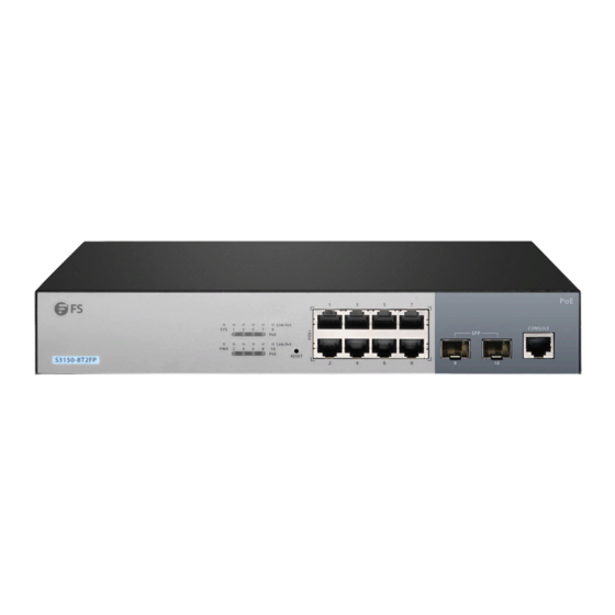
Page 3: Hardware Overview
Hardware Overview Front Panel Ports S3150-8T2FP/S3260-8T2FP RJ45 SFP Console S3260-16T4FP Lnk/Act CONSOLE Lnk/Act S3260-16T4FP RESET COMBO Console RJ45 RJ45/SFP Combo S3400-24T4FP COMBO LnK/Act CONSOLE LnK/Act S3400-24T4FP RESET RJ45 RJ45/SFP Combo Console S3400-48T4SP SFP+ SFP+ RESET RESET CONSOLE CONSOLE RJ45 SFP+ Console... -
Page 4: Front Panel Button
Front Panel Button COMBO LnK/Act CONSOLE LnK/Act S3400-24T4FP RESET RESET Button Description Reset Restart and restore factory default settings. Front Panel LEDs Lnk/Act COMBO LnK/Act CONSOLE LnK/Act S3400-24T4FP RESET LEDs Status Description Switch is powered on. Blinking Green System is working properly. ON/OFF System is working not properly. -
Page 5: Back Panel
Back Panel Power ON/OFF Power Supply (DC) Grounding Point Power Supply (AC) Installation Requirements Before you begin the installation, make sure that you have the following: Phillips screwdriver. Standard-sized, 19" wide rack with a minimum of 1U height available. Category 5e or higher RJ45 Ethernet cables for connecting the network devices. Site Environment: Do not operate it in an area that exceeds an ambient temperature of 50ºC. -
Page 6: Mounting The Switch
Mounting the Switch Desk Mounting 1. Attach four rubber pads to the bottom. 2. Place the chassis on a desk. Rack Mounting 1. Secure the mounting brackets to the two sides of the switch with eight M3 screws. -
Page 7: Grounding The Switch
2. Attach the switch to the rack using four M6 screws and cage nuts. Grounding the Switch 1. Connect one end of the grounding cable to a proper earth ground, such as the rack in which the switch is mounted. 2. -
Page 8: Connecting The Power
Connecting the Power 1. Plug the AC power cord into the power port on the back of the switch. 2. Connect the other end of the power cord to an AC power source. WARNING: Do not install power cables while the power is on. Connecting the RJ45 Ports 1. -
Page 9: Connecting The Console Port
Connecting the SFP/SFP+ Ports 1. Plug the compatible SFP/SFP+ transceiver into the SFP/SFP+ port. 2. Connect a ber optic cable to the ber transceivers. Then connect the other end of the cable to other ber devices. WARNING: Laser beams will cause eye damage. Do not look into bores of optical modules or optical bers without eye protection. - Page 10 Con guring the Switch Con guring the Switch Using the Web-based Interface Step 1: Connect the computer to any Ethernet port of the switch using the network cable. Step 2: Set the IP address of the computer to 192.168.1.x. ("x" is any number from 2 to 254.). Set the subnet mask of the computer to 255.255.255.0.
-
Page 11: Troubleshooting
Quick Connect Protocol: Serial Flow Control Port: COM3 DTR/DSR 115200 Baud rate: RTS/CTS Data bits: XON/XOFF Parity: None Stop bits: Name of pipe: Show quick connect on startup Save session Open in a tab Connect Cancel Step 4: Enter the default username and password, admin/admin. Troubleshooting Loading Failure Troubleshooting After loading fails, the system will keep running in the original version. -
Page 12: Support And Other Resources
Product Warranty FS ensures our customers that any damage or faulty items due to our workmanship, we will o er a free return within 30 Days from the day you receive your goods. This excludes any custom made items or tailored solutions.
Need help?
Do you have a question about the S3150-8T2FP and is the answer not in the manual?
Questions and answers