
Related Manuals for FS S3400-48T6SP


Summary of Contents for FS S3400-48T6SP
- Page 1 S3 40 0-4 8T 6S P PO E+ S3400-48T6SP ETHERNET L2+ POE+ SWITCH ETHERNET L2+ POE+ SWITCH SWITCH ETHERNET L2+ POE+ Quick Start Guide V1.0 Quick-Start Anleitung Guide de Démarrage Rapide...
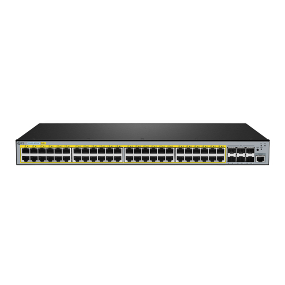
- Page 2 Introduction Thank you for choosing the S3400-48T6SP Ethernet L2+ PoE+ Switch. This guide is designed to familiarize you with the layout of the switch and describes how to deploy it in your network. S3400-48T6SP POE+ S3400-48T6SP Accessories Power Cord x1...
-
Page 3: Hardware Overview
Hardware Overview Front Panel Ports CONSOLE S3400-48T6SP POE+ RJ45 SFP+ Ports Description RJ45 10/100/1000BASE-T ports for Ethernet connection SFP+ SFP+ ports for 10G connection CONSOLE An RJ45 console port for serial management Front Panel LEDs RJ45 SYS PoE S3400-48T6SP POE+... -
Page 4: Installation Requirements
Front Panel Button S3400-48T6SP POE+ SWAP Button Description SWAP Swap function, used to switch PoE indication. Back Panel Power ON/OFF POWER Input:100-240Vac Freq:50/60Hz Power Supply (DC) Grounding Point Power Supply (AC) Installation Requirements Before the installation, make sure that you have the following: Screwdriver, static-proof wristband, and other Ethernet terminal devices. -
Page 5: Mounting The Switch
Be sure that the switch is level and stable to avoid any hazardous conditions. Do not install the equipment in a dusty environment. The installation site must be free from leaking or dripping water, heavy dew, and humidity. Ensure the rack and working platforms are well-earthed. S3 40 0- 48 T6 PO E+ Mounting the switch... -
Page 6: Rack Mounting
Rack Mounting 1. Secure the mounting brackets to the two sides of the switch with the supplied screws. 2. Attach the switch to the rack using the screws. NOTE: When you fix the brackets, the front panel of the switch faces forward. -
Page 7: Grounding The Switch
Grounding the Switch S3 40 0- 48 T6 SP PO E+ P O W E 4 0 V a c 1 0 0 -2 In p u t: 0 /6 0 H F re q :5 O F F 1. Connect one end of the grounding cable to a proper earth ground, such as the rack in which the switch is mounted. -
Page 8: Connecting The Console Port
1. Connect an Ethernet cable to the RJ45 port of a network device. 2. Connect the other end of the Ethernet cable to the RJ45 port of the switch. Connecting the SFP+ Ports 1. Plug the compatible SFP+ transceiver into the SFP+ port. 2. -
Page 9: Connecting The Power
1. Insert the RJ45 connector into the RJ45 console port on the front panel of the switch. 2. Connect the DB9 female connector of the console cable to the serial port on the computer. Connecting the Power P O W E R V a c 0 0 -2 4 0 In p u t: 1... - Page 10 Quick Connect Protocol: Serial The port may be manually entered or selected from the list. Flow Control Port: COM3 DTR/DSR 115200 Baud rate: RTS/CTS Data bits: XON/XOFF Parity: None Stop bits: Name of pipe: Show quick connect on startup Save session Open in a tab Connect Cancel...
-
Page 11: Troubleshooting
Step 3: Open a browser, type http://192.168.1.1 and enter the default username and password, admin/admin. IE 8/9/10/11, Google Chrome, Firefox are supported admin ***** Login Step 4: Click Login to display the web-based configuration page. Troubleshooting Faults Related to Power and Cooling Systems When the power switch is at the “ON”... -
Page 12: Online Resources
Contact Us Product Warranty FS ensures our customers that for any damage or faulty items due to our workmanship, we will offer a free return within 30 days from the day you receive your goods. This excludes any custom-made items or tailored solutions. - Page 13 Einführung Vielen Dank, dass Sie sich für den S3400-48T6SP Ethernet L2+ PoE+ Switch entschieden haben. Diese Anleitung soll Sie mit dem Aufbau des Switches vertraut machen und beschreibt, wie Sie ihn in Ihrem Netzwerk einsetzen. S3400-48T6SP POE+ S3400-48T6SP Zubehör Netzkabel x1...
- Page 14 Hardware-Übersicht Ports an der Vorderseite CONSOLE S3400-48T6SP POE+ RJ45 SFP+ Port Beschreibung RJ45 10/100/1000BASE-T-Ports für Ethernet-Anschluss SFP+ SFP+-Ports für 10G-Verbindung CONSOLE Ein RJ45-Console-Port für die serielle Verwaltung LEDs an der Vorderseite RJ45 SYS PoE S3400-48T6SP POE+ SFP+ Status Beschreibung Der Switch ist eingeschaltet.
- Page 15 Taste an der Vorderseite S3400-48T6SP POE+ SWAP Taste Beschreibung SWAP Swap-Funktion, wird zum Umschalten der PoE-Anzeige verwendet. Rückseite Strom EIN/AUS POWER Input:100-240Vac Freq:50/60Hz Stromversorgung (DC) Erdungspunkt Stromversorgung (AC) Installationsvoraussetzungen Vergewissern Sie sich vor der Installation, dass Sie Folgendes zur Hand haben: Schraubendreher, statiksicheres Armband und andere Ethernet-Endgeräte.
-
Page 16: Montage Des Switches
Der Switch sollte mindestens 1 HE (44,45 mm) von den Geräten an seinen Seiten entfernt installiert werden. Achten Sie darauf, dass der Switch waagerecht und stabil steht, um gefährliche Bedingungen zu vermeiden. Installieren Sie das Gerät nicht in einer staubigen Umgebung. Der Installationsort muss frei von austretendem oder tropfendem Wasser, starkem Tau und Feuchtigkeit sein. - Page 17 Rack-Montage 1. Befestigen Sie die Montagehalterungen mit den mitgelieferten Schrauben an den beiden Seiten des Switches. 2. Befestigen Sie den Switch mit den Schrauben am Rack. HINWEIS: Wenn Sie die Halterungen befestigen, zeigt die Vorderseite des Switches nach vorne.
- Page 18 Erdung des Switches S3 40 0- 48 T6 SP PO E+ P O W E 4 0 V a c 1 0 0 -2 In p u t: 0 /6 0 H F re q :5 O F F 1. Schließen Sie ein Ende des Erdungskabels an eine geeignete Erdung an, z. B. an das Rack, in dem der Switch montiert ist.
- Page 19 1. Schließen Sie ein Ethernet-Kabel an den RJ45-Port eines Netzwerkgeräts an. 2. Schließen Sie das andere Ende des Ethernet-Kabels an den RJ45-Port des Switches an. Anschließen der SFP+-Ports 1. Stecken Sie den kompatiblen SFP+-Transceiver in den SFP+-Port. 2. Schließen Sie ein Glasfaserkabel an den Glasfaser-Transceiver an. Schließen Sie dann das andere Ende des Kabels an ein anderes Glasfasergerät an.
-
Page 20: Anschließen Der Stromversorgung
1. Stecken Sie den RJ45-Stecker in den RJ45-Console-Port an der Vorderseite des Switches. 2. Verbinden Sie die DB9-Buchse des Console-Kabels mit dem seriellen Anschluss des Computers. Anschließen der Stromversorgung P O W E R V a c 0 0 -2 4 0 In p u t: 1 0 /6 0 H z F re q :5... - Page 21 Quick Connect Protocol: Serial The port may be manually entered or selected from the list. Flow Control Port: COM3 DTR/DSR 115200 Baud rate: RTS/CTS Data bits: XON/XOFF Parity: None Stop bits: Name of pipe: Show quick connect on startup Save session Open in a tab Connect Cancel...
-
Page 22: Fehlersuche
Schritt 3: Öffnen Sie einen Browser, geben Sie http://192.168.1.1 ein und geben Sie den Standard-Benutzernamen und das Passwort admin/admin ein. IE 8/9/10/11, Google Chrome, Firefox are supported admin ***** Login Schritt 4: Klicken Sie auf Login, um die webbasierte Konfigurationsseite anzuzeigen. Fehlersuche Fehler im Zusammenhang mit dem Strom- und Kühlsystem Wenn der Power Switch auf "ON"... - Page 23 Kontakt Produktgarantie FS garantiert seinen Kunden, dass wir bei Schäden oder fehlerhaften Artikeln, die auf unsere Verarbeitung zurückzuführen sind, eine kostenlose Rückgabe innerhalb von 30 Tagen nach Erhalt der Ware anbieten. Dies gilt nicht für Sonderanfertigungen oder maßgeschneiderte Lösungen.
- Page 24 Introduction Nous vous remercions d'avoir choisi le Switch S3400-48T6SP Ethernet L2+ PoE+. Ce guide est conçu pour vous familiariser avec la configuration du Switch et décrit comment procéder à son déploiement S3400-48T6SP POE+ S3400-48T6SP Accessoires Câble d'Alimentation x1 Câble Console x1 Câble de Mise à...
-
Page 25: Aperçu Du Matériel
Aperçu du Matériel Ports du Panneau Frontal CONSOLE S3400-48T6SP POE+ RJ45 SFP+ Ports Description RJ45 Ports 10/100/1000BASE-T pour la connexion Ethernet SFP+ Ports SFP+ pour une connexion 10G CONSOLE Un port console RJ45 pour la gestion en série Indicateurs LED du Panneau Frontal... -
Page 26: Exigences D'installation
Bouton du Panneau Frontal S3400-48T6SP POE+ SWAP Bouton Description SWAP Fonction de permutation, utilisée pour commuter le mode d'indication PoE. Panneau Arrière Mise en Marche/Arrêt POWER Input:100-240Vac Freq:50/60Hz Alimentation Electrique DC Point de Mise à la Terre Alimentation Electrique AC Exigences d'Installation Avant l'installation, assurez-vous que vous disposez des éléments suivants :... - Page 27 Assurez-vous que le switch est à niveau et stable pour éviter tout risque. Ne pas installer l'équipement dans un environnement poussiéreux. Le site d'installation doit être exempt de fuites ou de gouttes d'eau, de forte rosée et d'humidité. Assurez-vous que le rack et les plateformes de travail sont bien mis à la terre. S3 40 0- 48 T6 PO E+ Installation du Switch...
- Page 28 Montage en Rack 1. Fixez les supports de montage aux deux côtés du switch à l'aide des vis fournies. 2. Fixez le switch au rack à l'aide des vis. NOTE : Lorsque vous fixez les supports, le panneau frontal du switch est orienté vers l'avant.
- Page 29 Mise à la Terre du Switch S3 40 0- 48 T6 SP PO E+ P O W E 4 0 V a c 1 0 0 -2 In p u t: 0 /6 0 H F re q :5 O F F 1.
- Page 30 1. Connectez un câble Ethernet au port RJ45 d'un périphérique réseau. 2. Connectez l'autre extrémité du câble Ethernet au port RJ45 du switch. Connexion des Ports SFP+ 1. Branchez l'émetteur-récepteur SFP+ compatible sur le port SFP+. 2. Connectez un câble à fibre optique à l'émetteur-récepteur à fibre. Puis connectez l'autre extrémité du câble à...
-
Page 31: Connexion De L'alimentation
1. Insérez le connecteur RJ45 dans le port de console RJ45 situé sur le panneau frontal du Switch. 2. Connectez le connecteur femelle DB9 du câble de la console au port série de l'ordinateur. Connexion de l'Alimentation P O W E R V a c 0 0 -2 4 0 In p u t: 1... - Page 32 Quick Connect Protocol: Serial The port may be manually entered or selected from the list. Flow Control Port: COM3 DTR/DSR 115200 Baud rate: RTS/CTS Data bits: XON/XOFF Parity: None Stop bits: Name of pipe: Show quick connect on startup Save session Open in a tab Connect Cancel...
-
Page 33: Dépannage
Étape 3 : Ouvrez un navigateur, tapez http://192.168.1.1 et entrez le nom d'utilisateur et le mot de passe par défaut, admin/admin. IE 8/9/10/11, Google Chrome, Firefox are supported admin ***** Login Étape 4 : Cliquez sur Login pour afficher la page de configuration basée sur le Web. Dépannage Défauts Liés aux Systèmes d'Alimentation et de Refroidissement Lorsque l'interrupteur d'alimentation est sur la position "ON", vérifiez le fonctionnement du... -
Page 34: Garantie Du Produit
Contactey-nous Garantie du Produit FS garantit à ses clients que tout article endommagé ou défectueux dû à sa fabrication pourra être retourné gratuitement dans un délai de 30 jours à compter de la date de réception de la marchandise. Cette garantie ne s'applique pas aux articles fabriqués sur mesure ou aux solutions personnalisées. -
Page 35: Compliance Information
Die FS.COM GmbH erklärt hiermit, dass dieses Gerät mit der Richtlinie 2014/30/EU und 2014/35/EU konform ist. Eine Kopie der EU-Konformitätserklärung finden Sie unter www.fs.com/de/company/quality_control.html FS.COM GmbH déclare par la présente que cet appareil est conforme à la Directive 2014/30/UE et 2014/35/UE. Une copie de la Déclaration UE de Conformité est disponible sur https://www.fs.com/fr/company/quality_control.html FS.COM LIMITED... - Page 36 UKCA Hereby, FS.COM Innovation Ltd declares that this device is in compliance with the Directive SI 2016 No. 1091 and SI 2016 No. 1101. FS.COM LIMITED FS.COM Innovation Ltd 24F, Infore Center, No.19, Haitian 2nd Rd, Binhal 4th Floor Imperial House, 8 Kean Street, London,...
- Page 37 Q.C. PASSED Copyright © 2023 FS.COM All Rights Reserved.
Need help?
Do you have a question about the S3400-48T6SP and is the answer not in the manual?
Questions and answers