Table of Contents

Related Manuals for IEI Technology ICE-CV-D25501/N26001


Summary of Contents for IEI Technology ICE-CV-D25501/N26001
- Page 1 ICE-CV-D25501/N26001 COM Express Module IEI Technology Corp. MODEL: ICE-CV-D25501/N26001 COM Express R2.0 Module (Type 6), Intel® Atom™ D2550/N2600 Processor, DDR3 and RoHS Compliant User Manual Page i Rev. 1.00 – 17 September, 2012...
- Page 2 ICE-CV-D25501/N26001 COM Express Module Revision Date Version Changes 1.00 Initial release 17 September, 2012 Page ii...
- Page 3 ICE-CV-D25501/N26001 COM Express Module Copyright COPYRIGHT NOTICE The information in this document is subject to change without prior notice in order to improve reliability, design and function and does not represent a commitment on the part of the manufacturer. In no event will the manufacturer be liable for direct, indirect, special, incidental, or consequential damages arising out of the use or inability to use the product or documentation, even if advised of the possibility of such damages.
-
Page 4: Table Of Contents
ICE-CV-D25501/N26001 COM Express Module Table of Contents 1 INTRODUCTION......................1 1.1 I ......................2 NTRODUCTION 1.2 M ....................2 ODEL ARIATIONS 1.3 F ........................3 EATURES 1.4 C ......................3 ONNECTORS 1.5 D ....................... 4 IMENSIONS 1.6 D ........................ 5 1.7 T... - Page 5 ICE-CV-D25501/N26001 COM Express Module 5 BIOS ..........................35 5.1 I ......................36 NTRODUCTION 5.1.1 Starting Setup....................36 5.1.2 Using Setup ...................... 36 5.1.3 Getting Help..................... 37 5.1.4 Unable to Reboot after Configuration Changes ..........37 5.1.5 BIOS Menu Bar....................37 5.2 M...
- Page 6 ICE-CV-D25501/N26001 COM Express Module 6.5 LAN D ..................75 RIVER NSTALLATION 6.6 A ................. 77 UDIO RIVER NSTALLATION 6.7 USB 3.0 D ................79 RIVER NSTALLATION A BIOS OPTIONS ......................83 B ONE KEY RECOVERY ..................... 86 B.1 O ..............87...
- Page 7 ICE-CV-D25501/N26001 COM Express Module E HAZARDOUS MATERIALS DISCLOSURE ............135 E.1 H IPB P AZARDOUS ATERIALS ISCLOSURE ABLE FOR RODUCTS ERTIFIED AS HS C 2002/95/EC W ........136 OMPLIANT NDER ITHOUT ERCURY Page vii...
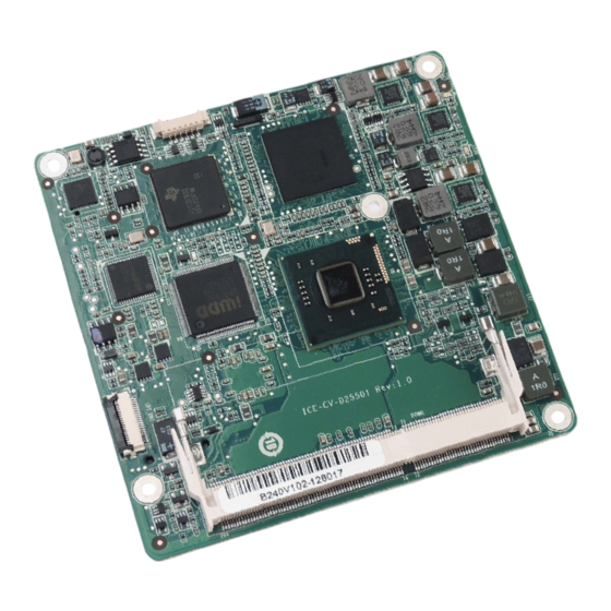
- Page 8 ICE-CV-D25501/N26001 COM Express Module List of Figures Figure 1-1: ICE-CV-D25501/N26001....................2 Figure 1-2: Connectors ........................3 Figure 1-3: ICE-CV-D25501/N26001 Dimensions (mm) ...............4 Figure 1-4: Data Flow Diagram......................5 Figure 3-1: Connectors ........................13 Figure 3-2: COM Express Connector AB Location ..............14 Figure 3-3: COM Express Connector CD Location ..............19 Figure 3-4: SO-DIMM Connector Location .................23...
- Page 9 ICE-CV-D25501/N26001 COM Express Module Figure 6-12: VGA Driver Setup Operations................74 Figure 6-13: VGA Driver Installation Finish Screen ..............74 Figure 6-14: LAN Driver Welcome Screen .................75 Figure 6-15: LAN Driver Installation ...................76 Figure 6-16: LAN Driver Installation Complete................76 Figure 6-17: Audio Driver Installation File Extraction...............77 Figure 6-18: Audio Driver Welcome Screen................78...
- Page 10 ICE-CV-D25501/N26001 COM Express Module Figure B-23: Disable Automatically Restart................104 Figure B-24: Launching the Recovery Tool ................105 Figure B-25: Auto Recovery Environment for Windows ............105 Figure B-26: Building the Auto Recovery Partition..............106 Figure B-27: Factory Default Image Confirmation ..............106 Figure B-28: Image Creation Complete ...................
- Page 11 ICE-CV-D25501/N26001 COM Express Module List of Tables Table 1-1: ICE-CV-D25501/N26001 Model Variations ..............2 Table 1-2: ICE-CV-D25501/N26001 Specifications...............7 Table 2-1: Packing List.........................11 Table 2-2: Optional Items......................11 Table 3-1: Peripheral Interface Connectors ................14 Table 3-2: COM Express Connector AB Pin Definitions............18 Table 3-3: COM Express Connector CD Pin Definitions............22 Table 3-4: SPI Flash Connector Pinouts ..................24...
- Page 12 ICE-CV-D25501/N26001 COM Express Module BIOS Menus BIOS Menu 1: Main ........................38 BIOS Menu 2: Advanced ......................39 BIOS Menu 3: ACPI Settings .......................40 BIOS Menu 4: RTC Wake Settings ....................41 BIOS Menu 5: Trusted Computing ....................42 BIOS Menu 6: CPU Configuration ....................43 BIOS Menu 7: IDE Configuration....................44...
-
Page 13: Introduction
ICE-CV-D25501/N26001 COM Express Module Chapter Introduction Page 1... -
Page 14: Introduction
Intel® Atom™ D2550/N2600 CPU and Intel® NM10 PCH. The COM Express standard allows the COM Express baseboard to be designed, while leaving the choice of processor till the later stages of design. The ICE-CV-D25501/N26001 provides a low power option with the full range of modern I/O options. The ICE-CV-D25501/N26001 embedded module is designed for flexible integration by system developers into customized platform devices. -
Page 15: Features
ICE-CV-D25501/N26001 COM Express Module 1.3 Features Some of the ICE-CV-D25501/N26001 COM Express module features are listed below: Complies with COM Express form factor Embedded Intel® Atom™ D2550/N2600 CPU and Intel® NM10 PCH Supports DDR3/DDR3L (1.35V) SO-DIMM Supports 24-bit single-channel LVDS, analog CRT (VGA) and dual DDI Supports USB 3.0, SATA 3Gb/s and GbE... -
Page 16: Dimensions
ICE-CV-D25501/N26001 COM Express Module 1.5 Dimensions The main dimensions of the ICE-CV-D25501/N26001 are shown in the diagram below. Figure 1-3: ICE-CV-D25501/N26001 Dimensions (mm) Page 4... -
Page 17: Data Flow
ICE-CV-D25501/N26001 COM Express Module 1.6 Data Flow F igure 1-4 shows the data flow between the system chipset, the CPU and other components installed on the motherboard. Figure 1-4: Data Flow Diagram Page 5... -
Page 18: Technical Specifications
ICE-CV-D25501/N26001 COM Express Module 1.7 Technical Specifications The ICE-CV-D25501/N26001 technical specifications are listed below. Specifications/Model ICE-CV-D25501/N26001 PICMG COM Express R2.0 Type 6 for compact size (95 mm x 95 mm) Form Factor 10 layers 1.86 GHz Intel® Atom™ D2550 dual-core CPU (2 x 512KB L2 cache) 1.6 GHz Intel®... -
Page 19: Table 1-2: Ice-Cv-D25501/N26001 Specifications
ICE-CV-D25501/N26001 COM Express Module Specifications/Model ICE-CV-D25501/N26001 Two USB 3.0 Eight USB 2.0 Two SATA 3Gb/s Two UART (by EC) HD Audio I/O Interfaces (Signal to Baseboard) GPIO SMBus +12V @ 0.45 A , Vcore_12V @ 1.0A (1.86 GHz Intel® Atom™ D2550... -
Page 20: Packing List
ICE-CV-D25501/N26001 COM Express Module Chapter Packing List Page 8... -
Page 21: Anti-Static Precautions
Only handle the edges of the PCB: Don't touch the surface of the motherboard. Hold the motherboard by the edges when handling. 2.2 Unpacking Precautions When the ICE-CV-D25501/N26001 is unpacked, please do the following: Follow the antistatic guidelines above. Make sure the packing box is facing upwards when opening. -
Page 22: Packing List
If any of the components listed in the checklist below are missing, do not proceed with the installation. Contact the IEI reseller or vendor the ICE-CV-D25501/N26001 was purchased from or contact an IEI sales representative directly by sending an email to ales@iei.com.tw. -
Page 23: Optional Items
ICE-CV-D25501/N26001 COM Express Module Quantity Item and Part Number Image Quick Installation Guide Table 2-1: Packing List 2.4 Optional Items The following are optional components which may be separately purchased: Item and Part Number Image Baseboard for COM Express Type 6 modules... -
Page 24: Connectors
ICE-CV-D25501/N26001 COM Express Module Chapter Connectors Page 12... -
Page 25: Peripheral Interface Connectors
ICE-CV-D25501/N26001 COM Express Module 3.1 Peripheral Interface Connectors This chapter details all the connectors. 3.1.1 ICE-CV-D25501/N26001 Layout The figure below shows all the connectors. Figure 3-1: Connectors Page 13... -
Page 26: Peripheral Interface Connectors
ICE-CV-D25501/N26001 COM Express Module 3.1.2 Peripheral Interface Connectors The table below lists all the connectors on the ICE-CV-D25501/N26001. Connector Type Label COM Express connector AB COM Express connector COM Express connector CD COM Express connector SO-DIMM connector SO-DIMM connector DIMM1... - Page 27 ICE-CV-D25501/N26001 COM Express Module Pin No. Description Pin No. Description GND15 GBE0_MDI3- GBE0_ACT# GBE0_MDI3+ LPC_FRAME# GBE0_LINK100# LPC_AD0 GBE0_LINK1000# LPC_AD1 GBE0_MDI2- LPC_AD2 GBE0_MDI2+ LPC_AD3 GBE0_LINK# LPC_DRQ0# GBE0_MDI1- LPC_DRQ1# GBE0_MDI1+ LPC_CLK GND1 GND16 GBE0_MDI0- PWRBTN# GBE0_MDI0+ SMB_CK GBE0_CTREF SMB_DAT SUS_S3# SMB_ALERT# SATA0_TX+...
- Page 28 ICE-CV-D25501/N26001 COM Express Module Pin No. Description Pin No. Description AC_SDOUT I2C_CK BIOS_DISABLE# I2C_DAT THRMTRIP# THRM# USB6- USB7- USB6+ USB7+ USB_6_7_OC# USB_4_5_OC# USB4- USB5- USB4+ USB5+ GND4 USB2- USB3- USB2+ USB3+ USB_2_3_OC# USB_0_1_OC# USB0- USB1- USB0+ USB1+ VCC_RTC EXCD1_PERST# EXCD0_PERST#...
- Page 29 ICE-CV-D25501/N26001 COM Express Module Pin No. Description Pin No. Description PCIE_TX1- PCIE_RX1- GND8 WAKE0# GPI2 WAKE1# PCIE_TX0+ PCIE_RX0+ PCIE_TX0- PCIE_RX0- GND9 GND22 LVDS_A0+ RSVD LVDS_A0- RSVD LVDS_A1+ RSVD LVDS_A1- RSVD LVDS_A2+ RSVD LVDS_A2- RSVD LVDS_VDD_EN RSVD LVDS_A3+ RSVD LVDS_A3- LVDS_BKLT_EN...
-
Page 30: Com Express Connector Cd
ICE-CV-D25501/N26001 COM Express Module Pin No. Description Pin No. Description RSVD RSVD RS1_TX RSVD RS1_RX RSVD A100 GND13 B100 GND25 A101 RS2_TX B101 FAN_PWMOUT A102 RS2_RX B102 FAN_TACHIN A103 LID# B103 SLEEP# A104 VCC_12V7 B104 VCC_12V16 A105 VCC_12V8 B105 VCC_12V17... -
Page 31: Figure 3-3: Com Express Connector Cd Location
ICE-CV-D25501/N26001 COM Express Module Figure 3-3: COM Express Connector CD Location Pin No. Description Pin No. Description GND0 GND15 USB_SSRX0- USB_SSTX0- USB_SSRX0+ USB_SSTX0+ USB_SSRX1- USB_SSTX1- USB_SSRX1+ USB_SSTX1+ RSVD RSVD RSVD RSVD GND1 GND16 RSVD RSVD RSVD RSVD RSVD DDI1_AUX+ RSVD... - Page 32 ICE-CV-D25501/N26001 COM Express Module Pin No. Description Pin No. Description GND2 GND17 RSVD RSVD RSVD RSVD DDI1_HPD RSVD RSVD RSVD RSVD DDI1_PAIR0+ RSVD DDI1_PAIR0- RSVD RSVD RSVD DDI1_PAIR1+ RSVD DDI1_PAIR1- GND3 GND18 DDI2_AUX+ DDI1_PAIR2+ DDI2_AUX- DDI1_PAIR2- DDI2_CTRLCLK DDI2_CTRLDATA RSVD RSVD...
- Page 33 ICE-CV-D25501/N26001 COM Express Module Pin No. Description Pin No. Description RSVD RSVD RSVD RSVD RSVD RSVD RSVD RSVD RSVD TYPE2# RSVD RSVD RSVD RSVD GND7 GND21 RSVD RSVD RSVD RSVD RSVD1 RSVD10 RSVD2 RSVD9 RSVD RSVD RSVD RSVD RSVD3 GND28...
-
Page 34: Table 3-3: Com Express Connector Cd Pin Definitions
ICE-CV-D25501/N26001 COM Express Module Pin No. Description Pin No. Description RSVD RSVD RSVD RSVD GND35 GND31 RSVD RSVD RSVD RSVD GND27 GND24 RSVD RSVD RSVD RSVD GND11 GND32 RSVD RSVD RSVD RSVD GND12 GND33 RSVD6 RSVD RSVD RSVD RSVD RSVD... -
Page 35: So-Dimm Connector
ICE-CV-D25501/N26001 COM Express Module 3.2.3 SO-DIMM Connector CN Label: DIMM1 204-pin DDR3 SO-DIMM connector CN Type: CN Location: See Figure 3-4 The SO-DIMM connector is for installing memory on the system. Figure 3-4: SO-DIMM Connector Location 3.2.4 SPI Connector CN Label:... -
Page 36: Figure 3-5: Spi Flash Connector Location
ICE-CV-D25501/N26001 COM Express Module Figure 3-5: SPI Flash Connector Location Description Description SPI_MOSI SPI_CLK SPI_MISO SPI_CS# SPI_VCC (+3.3V) Table 3-4: SPI Flash Connector Pinouts Page 24... -
Page 37: Installation
ICE-CV-D25501/N26001 COM Express Module Chapter Installation Page 25... -
Page 38: Anti-Static Precautions
ICE-CV-D25501/N26001 and severe injury to the user. Electrostatic discharge (ESD) can cause serious damage to electronic components, including the ICE-CV-D25501/N26001. Dry climates are especially susceptible to ESD. It is therefore critical that whenever the ICE-CV-D25501/N26001 or any other electrical component is handled, the following anti-static precautions are strictly adhered to. - Page 39 This helps to prevent potential ESD damage. Turn all power to the ICE-CV-D25501/N26001 off: When working with the ICE-CV-D25501/N26001, make sure that it is disconnected from all power supplies and that no electricity is being fed into the system.
-
Page 40: So-Dimm Installation
Figure 4-1. Figure 4-1: SO-DIMM Installation Step 1: Locate the SO-DIMM socket. Place the ICE-CV-D25501/N26001 on an anti-static pad with the solder side facing up. Step 2: Align the SO-DIMM with the socket. The SO-DIMM must be oriented in such a way that the notch in the middle of the SO-DIMM must be aligned with the plastic bridge in the socket. -
Page 41: Mounting The Ice-Cv-D25501/N26001 To An Optional Baseboard
Make sure to maintain the heatspreader plate temperature under 60°C in operation. Follow the steps below to install the ICE-CV-D25501/N26001 to the optional baseboard. Step 1: Align the two COM Express connectors on the reverse side of ICE-CV-D25501/N26001 with the corresponding connectors on the baseboard. -
Page 42: Figure 4-2: Connect The Com Express Connectors
ICE-CV-D25501/N26001 COM Express Module Figure 4-2: Connect the COM Express Connectors Step 2: Place the supplied heat sink on the heatspreader plate, aligning the four retention screw holes (Figure 4-3). Ensure to apply thermal paste to the heat sink or heatspreader plate for optimum heat dissipation. -
Page 43: Installing Usb 3.0 Driver During Windows® 7 Os Installation
ICE-CV-D25501/N26001 COM Express Module Step 3: Place the heatspreader plate with the heat sink on the ICE-CV-D25501/N26001, aligning the four retention screw holes (Figure 4-4). Step 4: Secure the heatspreader plate with the heat sink onto the baseboard with four retention screws (Figure 4-4). -
Page 44: Figure 4-5: Install Now
ICE-CV-D25501/N26001 COM Express Module Figure 4-5: Install Now Figure 4-6: Load Driver Step 3: Locate the USB 3.0 driver folder, select Driver, and then click OK (Figure 4-7). Page 32... -
Page 45: Figure 4-7: Browse For Folder
ICE-CV-D25501/N26001 COM Express Module Figure 4-7: Browse for Folder Step 4: Make sure the ASMedia XHCI Controller driver is selected, and then click Next. Figure 4-8: Select the ASMedia XHCI Controller Driver Page 33... -
Page 46: Figure 4-9: Confirm The Driver File
ICE-CV-D25501/N26001 COM Express Module Step 5: Click OK to continue (Figure 4-9). Figure 4-9: Confirm the Driver File Step 6: Make sure the Driver subfolder inside the USB 3.0 driver folder is selected, and then click OK (Figure 4-7). Step 7: Select the USB Root Hub driver and click Next. -
Page 47: Bios
ICE-CV-D25501/N26001 COM Express Module Chapter BIOS Page 35... -
Page 48: Introduction
ICE-CV-D25501/N26001 COM Express Module 5.1 Introduction The BIOS is programmed onto the BIOS chip. The BIOS setup program allows changes to certain system settings. This chapter outlines the options that can be changed. 5.1.1 Starting Setup The UEFI BIOS is activated when the computer is turned on. The setup program can be activated in one of two ways. -
Page 49: Getting Help
ICE-CV-D25501/N26001 COM Express Module Function Esc key Main Menu – Quit and not save changes into CMOS Status Page Setup Menu and Option Page Setup Menu -- Exit current page and return to Main Menu General help, only for Status Page Setup Menu and Option... -
Page 50: Main
ICE-CV-D25501/N26001 COM Express Module 5.2 Main The Main BIOS menu (BIOS Menu 1) appears when the BIOS Setup program is entered. The Main menu gives an overview of the basic system information. Aptio Setup Utility – Copyright (C) 2011 American Megatrends, Inc. -
Page 51: Advanced
ICE-CV-D25501/N26001 COM Express Module System Time [xx:xx:xx] Use the System Time option to set the system time. Manually enter the hours, minutes and seconds. 5.3 Advanced Use the Advanced menu (BIOS Menu 2) to configure the CPU and peripheral devices... -
Page 52: Rtc Wake Settings
ICE-CV-D25501/N26001 COM Express Module Aptio Setup Utility – Copyright (C) 2011 American Megatrends, Inc. Advanced ACPI Settings Select the highest ACPI sleep state the system will enter when the ACPI Sleep State [S1 (CPU Stop Clock)] SUSPEND button is pressed. -
Page 53: Bios Menu 4: Rtc Wake Settings
ICE-CV-D25501/N26001 COM Express Module Aptio Setup Utility – Copyright (C) 2011 American Megatrends, Inc. Advanced Wake system with Fixed Time [Disabled] Enable or disable System wake on alarm event. When enabled, System will wake on the date::hr::min::sec specified ---------------------- : Select Screen ↑... -
Page 54: Trusted Computing
ICE-CV-D25501/N26001 COM Express Module 5.3.3 Trusted Computing Use the Trusted Computing menu (BIOS Menu 5) to configure settings related to the Trusted Computing Group (TCG) Trusted Platform Module (TPM). Aptio Setup Utility – Copyright (C) 2011 American Megatrends, Inc. Advanced... -
Page 55: Cpu Configuration
ICE-CV-D25501/N26001 COM Express Module 5.3.4 CPU Configuration Use the CPU Configuration menu (BIOS Menu 6) to view detailed CPU specifications and configure the CPU. Aptio Setup Utility – Copyright (C) 2011 American Megatrends, Inc. Advanced CPU Configuration Enabled for Windows XP... -
Page 56: Ide Configuration
ICE-CV-D25501/N26001 COM Express Module Hyper-Threading [Enabled] Use the Hyper-Threading BIOS option to enable or disable the Intel Hyper-Threading Technology. Disabled Disables the Intel Hyper-Threading Technology. Enables the Intel Hyper-Threading Technology. Enabled EFAULT 5.3.5 IDE Configuration Use the IDE Configuration menu (BIOS Menu 7) to change and/or set the configuration of the SATA devices installed in the system. -
Page 57: Usb Configuration
ICE-CV-D25501/N26001 COM Express Module 5.3.6 USB Configuration Use the USB Configuration menu (BIOS Menu 8) to read USB configuration information and configure the USB settings. Aptio Setup Utility – Copyright (C) 2011 American Megatrends, Inc. Advanced USB Configuration Enables Legacy USB support. -
Page 58: Iwdd H/W Monitor
ICE-CV-D25501/N26001 COM Express Module Enabled Legacy USB support enabled EFAULT Legacy USB support disabled if no USB devices are Auto connected 5.3.7 iWDD H/W Monitor The iWDD H/W Monitor menu (BIOS Menu 9) displays the CPU fan speed and allows configuring the CPU fan speed value. -
Page 59: Super Io Configuration
ICE-CV-D25501/N26001 COM Express Module 5.3.8 Super IO Configuration Use the Super IO Configuration menu (BIOS Menu 10) to set or change the configurations for the serial ports. Aptio Setup Utility – Copyright (C) 2011 American Megatrends, Inc. Advanced Super IO Configuration... -
Page 60: Serial Port 1 Configuration
ICE-CV-D25501/N26001 COM Express Module 5.3.8.1.1 Serial Port 1 Configuration Serial Port [Enabled] Use the Serial Port option to enable or disable the serial port. Disabled Disable the serial port Enabled Enable the serial port EFAULT Change Settings [Auto] Use the Change Settings option to change the serial port IO port address and interrupt address. -
Page 61: Serial Port 2 Configuration
ICE-CV-D25501/N26001 COM Express Module 5.3.8.1.2 Serial Port 2 Configuration Serial Port [Enabled] Use the Serial Port option to enable or disable the serial port. Disabled Disable the serial port Enable the serial port Enabled EFAULT Change Settings [Auto] Use the Change Settings option to change the serial port IO port address and interrupt address. -
Page 62: H/W Monitor
ICE-CV-D25501/N26001 COM Express Module 5.3.9 H/W Monitor The H/W Monitor menu (BIOS Menu 12) contains the fan configuration submenus and displays operating temperature, fan speeds and system voltages. Aptio Setup Utility – Copyright (C) 2011 American Megatrends, Inc. Advanced PC Health Status... -
Page 63: Smart Fan Mode Configuration
ICE-CV-D25501/N26001 COM Express Module 5.3.9.1 Smart Fan Mode Configuration Use the Smart Fan Mode Configuration submenu (BIOS Menu 13) to configure fan temperature and speed settings. Aptio Setup Utility – Copyright (C) 2011 American Megatrends, Inc. Advanced Smart Fan Mode Configuration... -
Page 64: Serial Port Console Redirection
ICE-CV-D25501/N26001 COM Express Module SYSFAN1/SYSFAN2 expect PWM Output/DC Voltage Output Use the + or – key to change the value. Enter a decimal number between 0 and 255. SYSFAN1/SYSFAN2 Target Temperature Use the + or – key to change the value. Enter a decimal number between 0 and 127. -
Page 65: Bios Menu 14: Serial Port Console Redirection
ICE-CV-D25501/N26001 COM Express Module Aptio Setup Utility – Copyright (C) 2011 American Megatrends, Inc. Advanced COM1 Console Redirection Console Redirection [Disabled] Enable or Disable > Console Redirection Settings COM2 Console Redirection [Disabled] --------------------- > Console Redirection Settings : Select Screen ↑... - Page 66 ICE-CV-D25501/N26001 COM Express Module 9600 Sets the serial port transmission speed at 9600. Sets the serial port transmission speed at 19200. 19200 38400 Sets the serial port transmission speed at 38400. 57600 Sets the serial port transmission speed at 57600.
-
Page 67: Iei Feature
ICE-CV-D25501/N26001 COM Express Module Sets the number of stop bits at 1. EFAULT Sets the number of stop bits at 2. 5.3.11 iEi Feature Use the iEi Feature menu (BIOS Menu 15) to configure One Key Recovery function. Aptio Setup Utility – Copyright (C) 2011 American Megatrends, Inc. -
Page 68: Chipset
ICE-CV-D25501/N26001 COM Express Module 5.4 Chipset Use the Chipset menu (BIOS Menu 16) to access the Host Bridge and Southbridge configuration menus. WARNING! Setting the wrong values for the Chipset BIOS selections in the Chipset BIOS menu may cause the system to malfunction. -
Page 69: Intel Igd Configuration
ICE-CV-D25501/N26001 COM Express Module Aptio Setup Utility – Copyright (C) 2011 American Megatrends, Inc. Chipset > Intel IGD Configuration Config Intel IGD Settings. ******* Memory Information ******* Memory Frequency 1067 MHz(DDR3) Total Memory 2048 MB DIMM#1 2048 MB --------------------- : Select Screen ↑... - Page 70 ICE-CV-D25501/N26001 COM Express Module IGFX - Boot Type [VBIOS Default] Use the IGFX - Boot Type option to select the display device used by the system when it boots. Configuration options are listed below. VBIOS Default EFAULT Display Port 1...
-
Page 71: South Bridge Configuration
ICE-CV-D25501/N26001 COM Express Module 128MB EFAULT 256MB 5.4.2 South Bridge Configuration Use the South Bridge Configuration menu (BIOS Menu 19) to configure the Southbridge chipset. Aptio Setup Utility – Copyright (C) 2011 American Megatrends, Inc. Chipset Restore AC Power Loss... -
Page 72: Boot
ICE-CV-D25501/N26001 COM Express Module Disabled The spread spectrum mode is disabled EFAULT The spread spectrum mode is enabled Enabled 5.5 Boot Use the Boot menu (BIOS Menu 20) to configure system boot options. Aptio Setup Utility – Copyright (C) 2011 American Megatrends, Inc. - Page 73 ICE-CV-D25501/N26001 COM Express Module Does not enable the keyboard Number Lock automatically. To use the 10-keys on the keyboard, press the Number Lock key located on the upper left-hand corner of the 10-key pad. The Number Lock LED on the keyboard lights up when the Number Lock is engaged.
-
Page 74: Security
ICE-CV-D25501/N26001 COM Express Module 5.6 Security Use the Security menu (BIOS Menu 21) to set system and user passwords. Aptio Setup Utility – Copyright (C) 2011 American Megatrends, Inc. Main Advanced Chipset Boot Security Save & Exit Password Description Set Setup Administrator Password If ONLY the Administrator’s password is set,... -
Page 75: Bios Menu 22: Save & Exit
ICE-CV-D25501/N26001 COM Express Module Aptio Setup Utility – Copyright (C) 2011 American Megatrends, Inc. Main Advanced Chipset Boot Security Save & Exit Save Changes and Reset Reset the system after Discard Changes and Reset saving the changes. Restore Defaults Save as User Defaults... -
Page 76: Software Drivers
ICE-CV-D25501/N26001 COM Express Module Chapter Software Drivers Page 64... -
Page 77: Available Software Drivers
ICE-CV-D25501/N26001 COM Express Module 6.1 Available Software Drivers NOTE: The content of the CD may vary throughout the life cycle of the product and is subject to change without prior notice. Visit the IEI website or contact technical support for the latest updates. -
Page 78: Figure 6-1: Start Up Screen
ICE-CV-D25501/N26001 COM Express Module Figure 6-1: Start Up Screen Step 3: Click ICE-CV-D25501/N26001. Step 4: The list of drivers in Figure 6-2 appears. Figure 6-2: Drivers Page 66... -
Page 79: Chipset Driver Installation
ICE-CV-D25501/N26001 COM Express Module 6.3 Chipset Driver Installation To install the chipset driver, please do the following. Step 1: Access the driver list. (See Section 6.2) Step 2: Click “1-Chipset”. Step 3: Go to the 32-bit or 64-bit folder that corresponds to your OS version. -
Page 80: Figure 6-4: Chipset Driver Welcome Screen
ICE-CV-D25501/N26001 COM Express Module Figure 6-4: Chipset Driver Welcome Screen Step 8: Click Next to continue. Step 9: The license agreement in Figure 6-5 appears. Step 10: Read the License Agreement. Step 11: Click Yes to continue. Page 68... -
Page 81: Figure 6-5: Chipset Driver License Agreement
ICE-CV-D25501/N26001 COM Express Module Figure 6-5: Chipset Driver License Agreement Step 12: The Read Me file in Figure 6-6 appears. Step 13: Click Next to continue. Figure 6-6: Chipset Driver Read Me File Step 14: Setup Operations are performed as shown in Figure 6-7. -
Page 82: Figure 6-7: Chipset Driver Setup Operations
ICE-CV-D25501/N26001 COM Express Module Figure 6-7: Chipset Driver Setup Operations Step 15: Once the Setup Operations are complete, click Next to continue. Step 16: The Finish screen appears. Step 17: Select “Yes, I want to restart the computer now” and click the Finish icon. -
Page 83: Vga Driver Installation
ICE-CV-D25501/N26001 COM Express Module Figure 6-8: Chipset Driver Installation Finish Screen 6.4 VGA Driver Installation NOTE: Due to Intel® GMA driver limitation, the monitor connected to the VGA connector may not have signal to it after restarting from the graphics driver installation. -
Page 84: Figure 6-9: Vga Driver Welcome Screen
ICE-CV-D25501/N26001 COM Express Module Figure 6-9: VGA Driver Welcome Screen Step 6: Click Next to continue. Step 7: The license agreement in Figure 6-10 appears. Step 8: Read the License Agreement. Step 9: Click Yes to continue. Page 72... -
Page 85: Figure 6-10: Vga Driver License Agreement
ICE-CV-D25501/N26001 COM Express Module Figure 6-10: VGA Driver License Agreement Step 10: The Read Me file in Figure 6-11 appears. Step 11: Click Next to continue. Figure 6-11: VGA Driver Read Me File Step 12: Setup Operations are performed as shown in Figure 6-12. -
Page 86: Figure 6-12: Vga Driver Setup Operations
ICE-CV-D25501/N26001 COM Express Module Figure 6-12: VGA Driver Setup Operations Step 13: Once the Setup Operations are complete, click the Next icon to continue. Step 14: The Finish screen appears. Step 15: Select “Yes, I want to restart the computer now” and click the Finish icon. -
Page 87: Lan Driver Installation
ICE-CV-D25501/N26001 COM Express Module 6.5 LAN Driver Installation To install the LAN driver, please do the following. Step 1: Access the driver list shown in Figure 6-2. (See Section 6.2) Step 2: Click “3-LAN”. Step 3: Go to the Realtek > Install_Win7_7048_09162011 folder. -
Page 88: Figure 6-15: Lan Driver Installation
ICE-CV-D25501/N26001 COM Express Module Figure 6-15: LAN Driver Installation Step 9: The program begins to install. Step 10: When the driver installation is complete, the screen in Figure 6-16 appears. Step 11: Click Finish to exit. Figure 6-16: LAN Driver Installation Complete... -
Page 89: Audio Driver Installation
ICE-CV-D25501/N26001 COM Express Module 6.6 Audio Driver Installation To install the Audio driver, please do the following. Step 1: Access the driver list. (See Section 6.2) Step 2: Click “4-Audio”. Step 3: Open the Win7 folder. Step 4: Double click the Vista_Win7_R263 icon. -
Page 90: Figure 6-18: Audio Driver Welcome Screen
ICE-CV-D25501/N26001 COM Express Module Figure 6-18: Audio Driver Welcome Screen Step 7: Click Next to continue. Step 8: The program begins to install. Step 9: The installation progress can be monitored in the progress bar shown in Figure 6-19. Figure 6-19: Audio Driver Installation... -
Page 91: Usb 3.0 Driver Installation
ICE-CV-D25501/N26001 COM Express Module Step 10: When the driver installation is complete, the screen in Figure 6-20 appears. Figure 6-20: Audio Driver Installation Complete Step 11: Select “Yes, I want to restart my computer now” and click Finish. Step 12: The system reboots. -
Page 92: Figure 6-21: Usb 3.0 Driver Welcome Screen
ICE-CV-D25501/N26001 COM Express Module Step 3: Locate the setup file and double click on it. Step 4: The Welcome Screen in Figure 6-21 appears. Step 5: Click Next to continue. Figure 6-21: USB 3.0 Driver Welcome Screen Step 6: The license agreement in Figure 6-22 appears. -
Page 93: Figure 6-22: Usb 3.0 Driver License Agreement
ICE-CV-D25501/N26001 COM Express Module Figure 6-22: USB 3.0 Driver License Agreement Step 9: The installation progress can be monitored in the progress bar shown in Figure 6-23. Figure 6-23: USB 3.0 Driver Setup Operations Step 10: When the driver installation is complete, the screen in Figure 6-24 appears Step 11: Click Finish to exit. -
Page 94: Figure 6-24: Usb 3.0 Driver Installation Finish Screen
ICE-CV-D25501/N26001 COM Express Module Figure 6-24: USB 3.0 Driver Installation Finish Screen Page 82... -
Page 95: Abios Options
ICE-CV-D25501/N26001 COM Express Module Appendix BIOS Options Page 83... - Page 96 ICE-CV-D25501/N26001 COM Express Module Below is a list of BIOS configuration options in the BIOS chapter. System Overview .........................38 System Date [xx/xx/xx] ......................38 System Time [xx:xx:xx] .......................39 ACPI Sleep State [S1 (CPU Stop Clock)] ................40 ...
- Page 97 ICE-CV-D25501/N26001 COM Express Module Fixed Graphics Memory Size [128MB]................58 Restore AC Power Loss [Last State] .................59 Set Spread Spectrum Function [Disabled]................59 Bootup NumLock State [On]....................60 Quiet Boot [Enabled] ......................61 Launch PXE OpROM [Disabled] ..................61 ...
-
Page 98: B One Key Recovery
ICE-CV-D25501/N26001 COM Express Module Appendix One Key Recovery Page 86... -
Page 99: One Key Recovery Introduction
ICE-CV-D25501/N26001 COM Express Module B.1 One Key Recovery Introduction The IEI one key recovery is an easy-to-use front end for the Norton Ghost system backup and recovery tool. This tool provides quick and easy shortcuts for creating a backup and reverting to that backup or reverting to the factory default settings. -
Page 100: System Requirement
ICE-CV-D25501/N26001 COM Express Module After completing the five initial setup procedures as described above, users can access the recovery tool by pressing <F3> while booting up the system. The detailed information of each function is described in Section B.5. NOTE:... -
Page 101: Supported Operating System
ICE-CV-D25501/N26001 COM Express Module partitions. Please take the following table as a reference when calculating the size of the partition. OS Image after Ghost Compression Ratio Windows® 7 7 GB 5 GB Windows® XPE 776 MB 560 MB Windows® CE 6.0... -
Page 102: Setup Procedure For Windows
ICE-CV-D25501/N26001 COM Express Module Linux Fedora Core 12 (Constantine) Fedora Core 11 (Leonidas) Fedora Core 10 (Cambridge) Fedora Core 8 (Werewolf) Fedora Core 7 (Moonshine) RedHat RHEL-5.4 RedHat 9 (Ghirke) Ubuntu 8.10 (Intrepid) Ubuntu 7.10 (Gutsy) Ubuntu 6.10 (Edgy) Debian 5.0 (Lenny) Debian 4.0 (Etch) -
Page 103: Hardware And Bios Setup
ICE-CV-D25501/N26001 COM Express Module The detailed descriptions are described in the following sections. NOTE: The setup procedures described below are for Microsoft Windows operating system users. For Linux, most of the setup procedures are the same except for several steps described in Section B .3. -
Page 104: Figure B-2: Launching The Recovery Tool
ICE-CV-D25501/N26001 COM Express Module Step 2: Boot the system from recovery CD. When prompted, press any key to boot from the recovery CD. It will take a while to launch the recovery tool. Please be patient! Figure B-2: Launching the Recovery Tool Step 3: The recovery tool setup menu is shown as below. -
Page 105: Figure B-4: Command Prompt
ICE-CV-D25501/N26001 COM Express Module Figure B-4: Command Prompt Step 5: The command prompt window appears. Type the following commands (marked in red) to create two partitions. One is for the OS installation; the other is for saving recovery files and images which will be an invisible partition. -
Page 106: Figure B-5: Partition Creation Commands
ICE-CV-D25501/N26001 COM Express Module Figure B-5: Partition Creation Commands Page 94... -
Page 107: Install Operating System, Drivers And Applications
ICE-CV-D25501/N26001 COM Express Module NOTE: Use the following commands to check if the partitions were created successfully. Step 6: Press any key to exit the recovery tool and automatically reboot the system. Please continue to the following procedure: Build the Recovery Partition.S t e p 0 :... -
Page 108: Build-Up Recovery Partition
ICE-CV-D25501/N26001 COM Express Module B.2.4 Build-up Recovery Partition Step 1: Put the recover CD in the optical drive. Step 2: Start the system. Step 3: Boot the system from the recovery CD. When prompted, press any key to boot from the recovery CD. It will take a while to launch the recovery tool. Please... -
Page 109: Figure B-8: Building The Recovery Partition
ICE-CV-D25501/N26001 COM Express Module Step 5: The Symantec Ghost window appears and starts configuring the system to build a recovery partition. In this process the partition created for recovery files in Section B .2.2 is hidden and the recovery tool is saved in this partition. -
Page 110: Create Factory Default Image
ICE-CV-D25501/N26001 COM Express Module B.2.5 Create Factory Default Image NOTE: Before creating the factory default image, please configure the system to a factory default environment, including driver and application installations. To create a factory default image, please follow the steps below. -
Page 111: Figure B-12: About Symantec Ghost Window
ICE-CV-D25501/N26001 COM Express Module Figure B-12: About Symantec Ghost Window Step 4: Use mouse to navigate to the option shown below ( F igure B-13). Figure B-13: Symantec Ghost Path Step 5: Select the local source drive (Drive 1) as shown in F igure B-14. -
Page 112: Figure B-14: Select A Local Source Drive
ICE-CV-D25501/N26001 COM Express Module Figure B-14: Select a Local Source Drive Step 6: Select a source partition (Part 1) from basic drive as shown in F igure B-15. Then click OK. Figure B-15: Select a Source Partition from Basic Drive Step 7: Select 1.2: [Recovery] NTFS drive and enter a file name called... -
Page 113: Figure B-16: File Name To Copy Image To
ICE-CV-D25501/N26001 COM Express Module Figure B-16: File Name to Copy Image to Step 8: When the Compress Image screen in F igure B-17 prompts, click High to make the image file smaller. Figure B-17: Compress Image Page 101... -
Page 114: Figure B-18: Image Creation Confirmation
ICE-CV-D25501/N26001 COM Express Module Step 9: The Proceed with partition image creation window appears, click Yes to continue. Figure B-18: Image Creation Confirmation Step 10: The Symantec Ghost starts to create the factory default image ( F igure B-19). Figure B-19: Image Creation Complete... -
Page 115: Auto Recovery Setup Procedure
ICE-CV-D25501/N26001 COM Express Module Step 12: The recovery tool main menu window is shown as below. Press any key to reboot the system. S t e p 0 : Figure B-21: Press Any Key to Continue B.3 Auto Recovery Setup Procedure... -
Page 116: Figure B-22: Auto Recovery Utility
ICE-CV-D25501/N26001 COM Express Module Step 1: Follow the steps described in Section B.2.1 ~ Section B.2.3 to setup BIOS, create partitions and install operating system. Step 2: Install the auto recovery utility into the system by double clicking the Utility/AUTORECOVERY-SETUP.exe in the One Key Recovery CD. This utility MUST be installed in the system, otherwise, the system will automatically restore from the factory default image every ten (10) minutes. -
Page 117: Figure B-24: Launching The Recovery Tool
ICE-CV-D25501/N26001 COM Express Module Step 4: Reboot the system from the recovery CD. When prompted, press any key to boot from the recovery CD. It will take a while to launch the recovery tool. Please be patient! Figure B-24: Launching the Recovery Tool Step 5: When the recovery tool setup menu appears, press <4>... -
Page 118: Figure B-26: Building The Auto Recovery Partition
ICE-CV-D25501/N26001 COM Express Module Figure B-26: Building the Auto Recovery Partition Step 7: After completing the system configuration, the following message prompts to confirm whether to create a factory default image. Type Y to have the system create a factory default image automatically. Type N within 6 seconds to skip this process (The default option is YES). -
Page 119: Figure B-28: Image Creation Complete
ICE-CV-D25501/N26001 COM Express Module Step 8: The Symantec Ghost starts to create the factory default image (Figure B-28). Figure B-28: Image Creation Complete Step 9: After completing the system configuration, press any key in the following window to restart the system. -
Page 120: Setup Procedure For Linux
ICE-CV-D25501/N26001 COM Express Module BIOS SETUP UTILITY Main Advanced PCIPNP Boot Security Chipset Exit iEi Feature ⎯⎯⎯⎯⎯⎯⎯⎯⎯⎯⎯⎯⎯⎯⎯⎯⎯⎯⎯⎯⎯⎯⎯⎯⎯⎯⎯ Auto Recovery Function [Enabled] Recover from PXE [Disabled] Select Screen ↑ ↓ Select Item Enter Go to SubScreen General Help Save and Exit Exit v02.61 ©Copyright 1985-2006, American Megatrends, Inc. -
Page 121: Figure B-31: Partitions For Linux
ICE-CV-D25501/N26001 COM Express Module Partition 1: / Partition 2: SWAP NOTE: Please reserve enough space for partition 3 for saving recovery images. Figure B-31: Partitions for Linux Step 3: Create a recovery partition. Insert the recovery CD into the optical disk drive. -
Page 122: Figure B-32: System Configuration For Linux
ICE-CV-D25501/N26001 COM Express Module recovery partition. After completing the system configuration, press any key to reboot the system. Eject the recovery CD. Figure B-32: System Configuration for Linux Step 5: Access the recovery tool main menu by modifying the “menu.lst”. To first access the recovery tool main menu, the menu.lst must be modified. -
Page 123: Recovery Tool Functions
ICE-CV-D25501/N26001 COM Express Module Step 7: The recovery tool menu appears. ( F igure B-34) Figure B-34: Recovery Tool Menu Step 8: Create a factory default image. Follow Step 2 Step 12 described in Section B .2.5 to create a factory default image. -
Page 124: Figure B-35: Recovery Tool Main Menu
ICE-CV-D25501/N26001 COM Express Module Figure B-35: Recovery Tool Main Menu The recovery tool has several functions including: 1. Factory Restore: Restore the factory default image (iei.GHO) created in Section B .2.5. 2. Backup system: Create a system backup image (iei_user.GHO) which will be saved in the hidden partition. -
Page 125: Factory Restore
ICE-CV-D25501/N26001 COM Express Module B.5.1 Factory Restore To restore the factory default image, please follow the steps below. Step 1: Type <1> and press <Enter> in the main menu. Step 2: The Symantec Ghost window appears and starts to restore the factory default. A factory default image called iei.GHO is created in the hidden Recovery partition. -
Page 126: Backup System
ICE-CV-D25501/N26001 COM Express Module B.5.2 Backup System To backup the system, please follow the steps below. Step 1: Type <2> and press <Enter> in the main menu. Step 2: The Symantec Ghost window appears and starts to backup the system. A backup image called iei_user.GHO is created in the hidden Recovery partition. -
Page 127: Restore Your Last Backup
ICE-CV-D25501/N26001 COM Express Module B.5.3 Restore Your Last Backup To restore the last system backup, please follow the steps below. Step 1: Type <3> and press <Enter> in the main menu. Step 2: The Symantec Ghost window appears and starts to restore the last backup image (iei_user.GHO). -
Page 128: Manual
ICE-CV-D25501/N26001 COM Express Module B.5.4 Manual To restore the last system backup, please follow the steps below. Step 1: Type <4> and press <Enter> in the main menu. Step 2: The Symantec Ghost window appears. Use the Ghost program to backup or recover the system manually. -
Page 129: Restore Systems From A Linux Server Through Lan
ICE-CV-D25501/N26001 COM Express Module B.6 Restore Systems from a Linux Server through LAN The One Key Recovery allows a client system to automatically restore to a factory default image saved in a Linux system (the server) through LAN connectivity after encountering a Blue Screen of Death (BSoD) or a hang for around 10 minutes. -
Page 130: Configure Dhcp Server Settings
ICE-CV-D25501/N26001 COM Express Module B.6.1 Configure DHCP Server Settings Step 1: Install the DHCP #yum install dhcp (CentOS, commands marked in red) #apt-get install dhcp3-server (Debian, commands marked in blue) Step 2: Confirm the operating system default settings: dhcpd.conf. CentOS Use the following command to show the DHCP server sample location: #vi /etc/dhcpd.conf... -
Page 131: Configure Tftp Settings
ICE-CV-D25501/N26001 COM Express Module filename “pxelinux.0”; B.6.2 Configure TFTP Settings Step 1: Install the tftp, httpd and syslinux. #yum install tftp-server httpd syslinux (CentOS) #apt-get install tftpd-hpa xinetd syslinux (Debian) Step 2: Enable the TFTP server by editing the “/etc/xinetd.d/tftp” file and make it use the remap file. -
Page 132: Configure One Key Recovery Server Settings
ICE-CV-D25501/N26001 COM Express Module Debian Replace the TFTP settings from “inetd” to “xinetd” and annotate the “inetd” by adding “#”. #vi /etc/inetd.conf Modify: #tftp dgram udp wait root /usr/sbin..(as shown below) #vi /etc/xinetd.d/tftp B.6.3 Configure One Key Recovery Server Settings Step 1: Copy the Utility/RECOVERYR10.TAR.BZ2 package from the One Key... -
Page 133: Start The Dhcp, Tftp And Http
ICE-CV-D25501/N26001 COM Express Module B.6.4 Start the DHCP, TFTP and HTTP Start the DHCP, TFTP and HTTP. For example: CentOS #service xinetd restart #service httpd restart #service dhcpd restart Debian #/etc/init.d/xinetd reload #/etc/init.d/xinetd restart #/etc/init.d/dhcp3-server restart B.6.5 Create Shared Directory Step 1: Install the samba. -
Page 134: Setup A Client System For Auto Recovery
ICE-CV-D25501/N26001 COM Express Module Modify: [image] comment = One Key Recovery path = /share/image browseable = yes writable = yes public = yes create mask = 0644 directory mask = 0755 Step 4: Edit “/etc/samba/smb.conf” for your environment. For example:... -
Page 135: Figure B-43: Disable Automatically Restart
ICE-CV-D25501/N26001 COM Express Module Figure B-43: Disable Automatically Restart Step 2: Configure the following BIOS options of the client system. Advanced → iEi Feature → Auto Recovery Function → Enabled Advanced → iEi Feature → Recover from PXE → Enabled Boot →... - Page 136 ICE-CV-D25501/N26001 COM Express Module MUST be installed in the system, otherwise, the system will automatically restore from the factory default image every ten (10) minutes. Step 6: Restart the client system from LAN. If the system encounters a Blue Screen of Death (BSoD) or a hang for around 10 minutes, it will automatically restore from the factory default image.
-
Page 137: Other Information
ICE-CV-D25501/N26001 COM Express Module NOTE: A firewall or a SELinux is not in use in the whole setup process described above. If there is a firewall or a SELinux protecting the system, modify the configuration information to accommodate them. B.7 Other Information B.7.1 Using AHCI Mode or ALi M5283 / VIA VT6421A Controller... - Page 138 ICE-CV-D25501/N26001 COM Express Module Step 5: When the following window appears, press <S> to select “Specify Additional Device”. Page 126...
-
Page 139: System Memory Requirement
ICE-CV-D25501/N26001 COM Express Module Step 6: In the following window, select a SATA controller mode used in the system. Then press <Enter>. The user can now start using the SATA HDD. Step 7: After pressing <Enter>, the system will get into the recovery tool setup menu. -
Page 140: C Terminology
ICE-CV-D25501/N26001 COM Express Module Appendix Terminology Page 128... - Page 141 ICE-CV-D25501/N26001 COM Express Module AC ’97 Audio Codec 97 (AC’97) refers to a codec standard developed by Intel® in 1997. ACPI Advanced Configuration and Power Interface (ACPI) is an OS-directed configuration, power management, and thermal management interface. AHCI Advanced Host Controller Interface (AHCI) is a SATA Host controller register-level interface.
- Page 142 ICE-CV-D25501/N26001 COM Express Module DIMM Dual Inline Memory Modules are a type of RAM that offer a 64-bit data bus and have separate electrical contacts on each side of the module. The digital inputs and digital outputs are general control signals that control the on/off circuit of external devices or TTL devices.
- Page 143 ICE-CV-D25501/N26001 COM Express Module LVDS Low-voltage differential signaling (LVDS) is a dual-wire, high-speed differential electrical signaling system commonly used to connect LCD displays to a computer. POST The Power-on Self Test (POST) is the pre-boot actions the system performs when the system is turned-on.
-
Page 144: Watchdog Timer
ICE-CV-D25501/N26001 COM Express Module Appendix Watchdog Timer Page 132... - Page 145 ICE-CV-D25501/N26001 COM Express Module NOTE: The following discussion applies to DOS environment. Contact IEI support or visit the IEI website for specific drivers for other operating systems. The Watchdog Timer is provided to ensure that standalone systems can always recover from catastrophic conditions that cause the CPU to crash.
- Page 146 ICE-CV-D25501/N26001 COM Express Module NOTE: When exiting a program it is necessary to disable the Watchdog Timer, otherwise the system resets. EXAMPLE PROGRAM: ; INITIAL TIMER PERIOD COUNTER W_LOOP: AX, 6F02H ;setting the time-out value BL, 30 ;time-out value is 48 seconds ;...
- Page 147 ICE-CV-D25501/N26001 COM Express Module Appendix Hazardous Materials Disclosure Page 135...
- Page 148 ICE-CV-D25501/N26001 COM Express Module E.1 Hazardous Materials Disclosure Table for IPB Products Certified as RoHS Compliant Under 2002/95/EC Without Mercury The details provided in this appendix are to ensure that the product is compliant with the Peoples Republic of China (China) RoHS standards. The table below acknowledges the presences of small quantities of certain materials in the product, and is applicable to China RoHS only.
- Page 149 ICE-CV-D25501/N26001 COM Express Module Part Name Toxic or Hazardous Substances and Elements Lead Mercury Cadmium Hexavalent Polybrominated Polybrominated Biphenyls Diphenyl (Pb) (Hg) (Cd) Chromium (CR(VI)) (PBB) Ethers (PBDE) Housing Display Printed Circuit Board Metal Fasteners Cable Assembly Fan Assembly Power Supply...
- Page 150 ICE-CV-D25501/N26001 COM Express Module 此附件旨在确保本产品符合中国 RoHS 标准。以下表格标示此产品中某有毒物质的含量符 合中国 RoHS 标准规定的限量要求。 本产品上会附有”环境友好使用期限”的标签,此期限是估算这些物质”不会有泄漏或突变”的 年限。本产品可能包含有较短的环境友好使用期限的可替换元件,像是电池或灯管,这些元 件将会单独标示出来。 部件名称 有毒有害物质或元素 铅 汞 镉 六价铬 多溴联苯 多溴二苯 醚 (Pb) (Hg) (Cd) (CR(VI)) (PBB) (PBDE) 壳体 显示 印刷电路板 金属螺帽 电缆组装 风扇组装 电力供应组装 电池 O: 表示该有毒有害物质在该部件所有物质材料中的含量均在 SJ/T11363-2006 标准规定的限量要求以下。...
Need help?
Do you have a question about the ICE-CV-D25501/N26001 and is the answer not in the manual?
Questions and answers