Sign In
Upload
Manuals
Brands
IEI Technology Manuals
Control Unit
ICE-CV-D25501-R10
IEI Technology ICE-CV-D25501-R10 Manuals
Manuals and User Guides for IEI Technology ICE-CV-D25501-R10. We have
1
IEI Technology ICE-CV-D25501-R10 manual available for free PDF download: User Manual
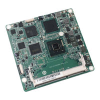
IEI Technology ICE-CV-D25501-R10 User Manual (150 pages)
COM Express R2.0 Module (Type 6), Intel Atom D2550/N2600 Processor, DDR3 and RoHS Compliant
Brand:
IEI Technology
| Category:
Control Unit
| Size: 7 MB
Table of Contents
Table of Contents
4
Introduction
13
Introduction
14
Model Variations
14
Figure 1-1: ICE-CV-D25501/N26001
14
Table 1-1: ICE-CV-D25501/N26001 Model Variations
14
Features
15
Connectors
15
Figure 1-2: Connectors
15
Dimensions
16
Figure 1-3: ICE-CV-D25501/N26001 Dimensions (MM)
16
Data Flow
17
Figure 1-4: Data Flow Diagram
17
Technical Specifications
18
Table 1-2: ICE-CV-D25501/N26001 Specifications
19
Packing List
20
Anti-Static Precautions
21
Unpacking Precautions
21
Packing List
22
Optional Items
23
Table 2-1: Packing List
23
Table 2-2: Optional Items
23
Connectors
24
Peripheral Interface Connectors
25
ICE-CV-D25501/N26001 Layout
25
Figure 3-1: Connectors
25
Peripheral Interface Connectors
26
Internal Peripheral Connectors
26
COM Express Connector AB
26
Figure 3-2: COM Express Connector AB Location
26
Table 3-1: Peripheral Interface Connectors
26
COM Express Connector CD
30
Table 3-2: COM Express Connector AB Pin Definitions
30
Figure 3-3: COM Express Connector CD Location
31
Table 3-3: COM Express Connector CD Pin Definitions
34
SO-DIMM Connector
35
SPI Connector
35
Figure 3-4: SO-DIMM Connector Location
35
Figure 3-5: SPI Flash Connector Location
36
Table 3-4: SPI Flash Connector Pinouts
36
Installation
37
Anti-Static Precautions
38
Installation Considerations
38
So-DIMM Installation
40
Figure 4-1: SO-DIMM Installation
40
Mounting the Ice-CV-D25501/N26001 to an Optional Baseboard
41
Figure 4-2: Connect the COM Express Connectors
42
Figure 4-3: Attach the Heat Sink to the Heatspreader Plate
42
Installing USB 3.0 Driver During Windows® 7 os Installation
43
Figure 4-4: Secure the Heatspreader Plate with the Heat Sink to the Baseboard
43
Figure 4-5: Install Now
44
Figure 4-6: Load Driver
44
Figure 4-7: Browse for Folder
45
Figure 4-8: Select the Asmedia XHCI Controller Driver
45
Figure 4-9: Confirm the Driver File
46
Figure 4-10: Select the USB Root Hub Driver
46
Bios
47
Introduction
48
Starting Setup
48
Using Setup
48
Getting Help
49
Unable to Reboot after Configuration Changes
49
BIOS Menu Bar
49
Table 5-1: BIOS Navigation Keys
49
Main
50
BIOS Menu 1: Main
50
Advanced
51
ACPI Settings
51
BIOS Menu 2: Advanced
51
RTC Wake Settings
52
BIOS Menu 3: ACPI Settings
52
BIOS Menu 4: RTC Wake Settings
53
Trusted Computing
54
BIOS Menu 5: Trusted Computing
54
CPU Configuration
55
BIOS Menu 6: CPU Configuration
55
IDE Configuration
56
BIOS Menu 7: IDE Configuration
56
USB Configuration
57
BIOS Menu 8: USB Configuration
57
Iwdd H/W Monitor
58
BIOS Menu 9: Iwdd H/W Monitor
58
Super IO Configuration
59
Serial Port N Configuration
59
BIOS Menu 10: Super IO Configuration
59
BIOS Menu 11: Serial Port N Configuration Menu
59
Serial Port 1 Configuration
60
Serial Port 2 Configuration
61
H/W Monitor
62
BIOS Menu 12: H/W Monitor
62
Smart Fan Mode Configuration
63
BIOS Menu 13: Smart Fan Mode Configuration
63
Serial Port Console Redirection
64
BIOS Menu 14: Serial Port Console Redirection
65
Iei Feature
67
BIOS Menu 15: Iei Feature
67
Chipset
68
Host Bridge Configuration
68
BIOS Menu 16: Chipset
68
Intel IGD Configuration
69
BIOS Menu 17: Host Bridge Configuration
69
BIOS Menu 18: Intel IGD Configuration
69
South Bridge Configuration
71
BIOS Menu 19: Southbridge Configuration
71
Boot
72
BIOS Menu 20: Boot
72
Security
74
Save & Exit
74
BIOS Menu 21: Security
74
BIOS Menu 22: Save & Exit
75
Software Drivers
76
Available Software Drivers
77
Starting the Driver Program
77
Figure 6-1: Start up Screen
78
Figure 6-2: Drivers
78
Chipset Driver Installation
79
Figure 6-3: Chipset Driver Screen
79
Figure 6-4: Chipset Driver Welcome Screen
80
Figure 6-5: Chipset Driver License Agreement
81
Figure 6-6: Chipset Driver Read Me File
81
Figure 6-7: Chipset Driver Setup Operations
82
Vga Driver Installation
83
Figure 6-8: Chipset Driver Installation Finish Screen
83
Figure 6-9: VGA Driver Welcome Screen
84
Figure 6-10: VGA Driver License Agreement
85
Figure 6-11: VGA Driver Read Me File
85
Figure 6-12: VGA Driver Setup Operations
86
Figure 6-13: VGA Driver Installation Finish Screen
86
Lan Driver Installation
87
Figure 6-14: LAN Driver Welcome Screen
87
Figure 6-15: LAN Driver Installation
88
Figure 6-16: LAN Driver Installation Complete
88
Audio Driver Installation
89
Figure 6-17: Audio Driver Installation File Extraction
89
Figure 6-18: Audio Driver Welcome Screen
90
Figure 6-19: Audio Driver Installation
90
Usb 3.0 Driver Installation
91
Figure 6-20: Audio Driver Installation Complete
91
Figure 6-21: USB 3.0 Driver Welcome Screen
92
Figure 6-22: USB 3.0 Driver License Agreement
93
Figure 6-23: USB 3.0 Driver Setup Operations
93
Figure 6-24: USB 3.0 Driver Installation Finish Screen
94
ABIOS Options
95
B One Key Recovery
98
One Key Recovery Introduction
99
Figure B-1: IEI One Key Recovery Tool Menu
99
System Requirement
100
Supported Operating System
101
Setup Procedure for Windows
102
Hardware and BIOS Setup
103
Create Partitions
103
Figure B-2: Launching the Recovery Tool
104
Figure B-3: Recovery Tool Setup Menu
104
Figure B-4: Command Prompt
105
Figure B-5: Partition Creation Commands
106
Install Operating System, Drivers and Applications
107
Build-Up Recovery Partition
108
Figure B-6: Launching the Recovery Tool
108
Figure B-7: Manual Recovery Environment for Windows
108
Figure B-8: Building the Recovery Partition
109
Figure B-9: Press any Key to Continue
109
Create Factory Default Image
110
Figure B-10: Press F3 to Boot into Recovery Mode
110
Figure B-11: Recovery Tool Menu
110
Figure B-12: about Symantec Ghost Window
111
Figure B-13: Symantec Ghost Path
111
Figure B-14: Select a Local Source Drive
112
Figure B-15: Select a Source Partition from Basic Drive
112
Figure B-16: File Name to Copy Image to
113
Figure B-17: Compress Image
113
Figure B-18: Image Creation Confirmation
114
Figure B-19: Image Creation Complete
114
Figure B-20: Image Creation Complete
114
Auto Recovery Setup Procedure
115
Figure B-21: Press any Key to Continue
115
Figure B-22: Auto Recovery Utility
116
Figure B-23: Disable Automatically Restart
116
Figure B-24: Launching the Recovery Tool
117
Figure B-25: Auto Recovery Environment for Windows
117
Figure B-26: Building the Auto Recovery Partition
118
Figure B-27: Factory Default Image Confirmation
118
Figure B-28: Image Creation Complete
119
Figure B-29: Press any Key to Continue
119
Setup Procedure for Linux
120
Figure B-30: IEI Feature
120
Figure B-31: Partitions for Linux
121
Figure B-32: System Configuration for Linux
122
Figure B-33: Access Menu.lst in Linux (Text Mode)
122
Recovery Tool Functions
123
Figure B-34: Recovery Tool Menu
123
Figure B-35: Recovery Tool Main Menu
124
Factory Restore
125
Figure B-36: Restore Factory Default
125
Figure B-37: Recovery Complete Window
125
Backup System
126
Figure B-38: Backup System
126
Figure B-39: System Backup Complete Window
126
Restore Your Last Backup
127
Figure B-40: Restore Backup
127
Figure B-41: Restore System Backup Complete Window
127
Manual
128
Figure B-42: Symantec Ghost Window
128
Restore Systems from a Linux Server through Lan
129
Configure DHCP Server Settings
130
Configure TFTP Settings
131
Configure One Key Recovery Server Settings
132
Start the DHCP, TFTP and HTTP
133
Create Shared Directory
133
Setup a Client System for Auto Recovery
134
Figure B-43: Disable Automatically Restart
135
Other Information
137
Using AHCI Mode or Ali M5283 / VIA VT6421A Controller
137
System Memory Requirement
139
C Terminology
140
Watchdog Timer
144
Advertisement
Advertisement
Related Products
IEI Technology ICE-CV-D25501/N26001
IEI Technology ICE-9652
IEI Technology ICE-9602
IEI Technology ICE-CV-N26001-R10
IEI Technology IVC-168G
IEI Technology IVC-268G
IEI Technology IVCE-268G
IEI Technology iQ7-ASL
IEI Technology iQ7-ASL-N2C
IEI Technology iQ7-ASL-E1C
IEI Technology Categories
Motherboard
Touch Panel
Computer Hardware
Single board computers
Desktop
More IEI Technology Manuals
Login
Sign In
OR
Sign in with Facebook
Sign in with Google
Upload manual
Upload from disk
Upload from URL